


 Loading...
User’s
Manual
Models CA100S and 200S
Capacitance Magnetic Flowmeter
IM 1E8B0-01E
IM 1E8B0-01E
8th Edition
Yokogawa Electric Corporation

NOTICE
Contents
1. INTRODUCTION ........................................................................................................ |
|
1-1 |
||
2. |
HANDLING PRECAUTIONS .................................................................................. |
2-1 |
||
|
2.1 |
Checking Model and Specifications ................................................................ |
2-1 |
|
|
2.2 |
Accessories ...................................................................................................... |
2-1 |
|
|
2.3 |
Storage Precautions ......................................................................................... |
2-2 |
|
|
2.4 |
Installation Location Precautions .................................................................... |
2-2 |
|
|
2.5 |
Converter Reorientation Precautions ............................................................... |
2-2 |
|
3. |
COMPONENT NAMES ............................................................................................ |
3-1 |
||
4. INSTALLATION.......................................................................................................... |
|
|
4-1 |
|
|
4.1 |
Piping Design Precautions ............................................................................... |
4-1 |
|
|
4.2 |
Mounting Precautions ...................................................................................... |
4-6 |
|
|
|
4.2.1 |
General Precautions ................................................................................. |
4-6 |
|
|
4.2.2 |
Flowmeter piping ..................................................................................... |
4-7 |
|
|
4.2.3 Alteration of LCD Display Orientation ................................................... |
4-7 |
|
|
4.3 |
Mounting ......................................................................................................... |
4-8 |
|
|
|
4.3.1 Nominal Diameter 15mm (0.5") to 40 mm (1.5") ................................... |
4-8 |
|
|
|
4.3.2 Nominal Diameter 50mm (2˝) to 200 m (8˝) ......................................... |
4-11 |
|
|
4.4 |
Wiring ............................................................................................................ |
4-14 |
|
|
|
4.4.1 |
Protective Grounding ............................................................................. |
4-14 |
|
|
4.4.2 |
General Precautions ............................................................................... |
4-15 |
|
|
4.4.3 Power and Output Cables ...................................................................... |
4-15 |
|
|
|
4.4.4 |
DC Connections ..................................................................................... |
4-16 |
|
|
4.4.5 |
Wiring Ports ........................................................................................... |
4-17 |
|
|
4.4.6 Connecting to External Instruments ...................................................... |
4-19 |
|
5. |
BASIC OPERATING PROCEDURES .................................................................... |
5-1 |
||
|
5.1 |
Liquid Crystal Display ..................................................................................... |
5-1 |
|
|
5.2 |
Types of Display Data ..................................................................................... |
5-2 |
|
|
|
5.2.1 Flow Rate Data Display Mode ................................................................. |
5-3 |
|
|
|
5.2.2 |
Setting Mode ............................................................................................ |
5-5 |
|
|
5.2.3 |
Alarm Display Mode ............................................................................... |
5-8 |
6. FUNCTION AND DATA SETTINGS ........................................................................ |
6-1 |
|||
|
6.1 |
Flow Rate Span Setting ................................................................................... |
6-2 |
|
|
6.2 |
Measuring Mode Setting ................................................................................. |
6-5 |
|
|
6.3 |
Other Functions and Settings ........................................................................... |
6-6 |
|
|
|
6.3.1 |
Pulse Output ............................................................................................. |
6-6 |
|
|
6.3.2 Display of Internal Totalization Values .................................................... |
6-8 |
|
|
|
6.3.3 Presetting for Totalization Display .......................................................... |
6-9 |
|
|
|
6.3.4 |
Damping Time Constant .......................................................................... |
6-9 |
|
|
6.3.5 Current Output During Alarm Occurrence ............................................ |
6-10 |
|
|
|
6.3.6 |
Reversing Flow Direction ...................................................................... |
6-10 |
|
|
6.3.7 Limiting on Current Output ................................................................... |
6-10 |
|
|
|
6.3.8 |
Alarm Output ......................................................................................... |
6-11 |
8th Edition : Oct. 2007
All right Reserved Copyright © 1994. Yokogawa Electric Corporation
IM 1E8B0-01E
i
NOTICE
|
6.3.9 |
Data Setting Enable/Inhibit .................................................................... |
6-12 |
|
6.3.10 |
Procedure of Selecting Special Application Items ................................. |
6-12 |
|
6.3.11 |
Rate Limit .............................................................................................. |
6-12 |
7. |
OPERATION VIA BRAIN TERMINAL ................................................................. |
7-1 |
|
|
7.1 |
Operation Via the BT200 ................................................................................. |
7-1 |
|
7.1.1 |
BT200 Connections ................................................................................. |
7-1 |
|
7.1.2 |
BT200 Keypad Layout ............................................................................. |
7-3 |
|
7.1.3 |
Major BT200 Key Functions ................................................................... |
7-4 |
|
7.1.4 |
Displaying Flow Rate Data ...................................................................... |
7-6 |
|
7.2 |
Setting Parameters ........................................................................................... |
7-7 |
|
7.2.1 |
Setting Flow Span .................................................................................... |
7-7 |
|
7.2.2 |
Measuring Mode Setting .......................................................................... |
7-8 |
|
7.2.3 |
Pulse Output (Refer to 6.3.1) ................................................................... |
7-9 |
|
7.2.4 |
Display of Internal Totalization (Refer to 6.3.2) ................................... |
7-10 |
|
7.2.5 |
Presetting Totalization Display (Refer to 6.3.3) .................................... |
7-11 |
|
7.2.6 |
Damping Time Constant (Refer to 6.3.4) .............................................. |
7-11 |
|
7.2.7 |
Current Output During Alarm Occurrence (Refer to 6.3.5) ................... |
7-11 |
|
7.2.8 |
Reversing Flow Direction (Refer to 6.3.6) ............................................ |
7-12 |
|
7.2.9 |
Limiting Current Output (Refer to 6.3.7) ............................................. |
7-12 |
|
7.2.10 |
Alarm Output (Refer to 6.3.8) ............................................................... |
7-13 |
|
7.2.11 |
Data Setting Enable / Inhibit (Refer to 6.3.9) ........................................ |
7-13 |
|
7.2.12 |
Procedure of Selecting Special Application Items (Refer to 6.3.10) ..... |
7-13 |
|
7.2.13 |
Rate Limit (Refer to 6.3.11) .................................................................. |
7-14 |
|
7.2.14 |
User-Defined Units ................................................................................ |
7-14 |
|
7.2.15 |
Other Important Points to Note .............................................................. |
7-15 |
8. |
ACTUAL OPERATION ............................................................................................. |
8-1 |
|
|
8.1 |
Pre - Operation Zero Adjustment ....................................................................... |
8-1 |
|
8.1.1 |
Zero Adjustment Using Data Setting Keys .............................................. |
8-2 |
|
8.1.2 |
Zero Adjustment Via the BT200 .............................................................. |
8-3 |
|
8.2 |
Self - diagnostics Functions ............................................................................... |
8-4 |
|
8.2.1 |
Display and Output Status during Alarm occurrence .............................. |
8-4 |
|
8.2.2 |
Error Description and Countermeasures .................................................. |
8-5 |
9. |
MAINTENANCE |
|
9-1 |
|
9.1 Loop Test (Test output) .................................................................................... |
9-1 |
|
|
9.1.1 |
Settings for Test Output Using Data Setting Keys ................................... |
9-1 |
|
9.1.2 |
Test Output Setting Via the BT200 .......................................................... |
9-2 |
|
9.2 |
Fuse Replacement ............................................................................................ |
9-2 |
|
9.3 |
Trouble Shooting ............................................................................................. |
9-3 |
|
9.3.1 |
No Indication ........................................................................................... |
9-3 |
|
9.3.2 |
Unstable Zero ........................................................................................... |
9-4 |
|
9.3.3 |
Disagreement of Indication with Actual Flow Result .............................. |
9-5 |
10. OUTLINE ................................................................................................................. |
|
10-1 |
|
|
10.1 ................................................................................. |
Standard Specifications |
10-1 |
|
10.1.1 ...................................................................... |
Magnetic Flow Converter |
10-1 |
|
10.1.2 .............................................................................. |
Magnetic Flow Tube |
10-2 |
|
10.2 .................................................................................... |
Standard Performance |
10-3 |
|
10.3 ....................................................................... |
Normal Operating Conditions |
10-4 |
ii |
IM 1E8B0-01E |
|
|
NOTICE |
10.4 |
Model and Specification Code ....................................................................... |
10-7 |
10.5 |
Optional Specifications .................................................................................. |
10-8 |
10.6 |
Sizing Data .................................................................................................... |
10-9 |
10.7 |
External Dimensions .................................................................................... |
10-10 |
10.8 |
Earth Ring Inside Diameter ......................................................................... |
10-11 |
11. OPERATING PRINCIPLE ..................................................................................... |
11-1 |
|
11.1 |
Principle of Magnetic Flowmeter Operation ................................................. |
11-1 |
11.2 |
Principal and Features of the capacitance Magnetic flowmeter .................... |
11-2 |
11.3 |
Capacitance Magnetic flowmeter circuit Configuration ................................ |
11-2 |
12. PARAMETER SUMMARY .................................................................................... |
12-1 |
|
13. HAZARDOUS DUTY TYPE INSTRUMENT ...................................................... |
13-1 |
|
13.1 |
FM (Only for sizes 15 to 100 mm(0.5 to 4 in)) ............................................ |
13-1 |
13.2 |
CSA (Only for sizes 15 to 100 mm(0.5 to 4 in)) ........................................... |
13-2 |
13.3 |
TIIS(JIS) (Only for sizes 15 to 100 mm(0.5 to 4 in)) ................................... |
13-3 |
INSTALLATION AND OPERATING PRECAUTIONS FOR JIS FLAMEPROOF |
||
EQUIPMENT ......................................................................................................... |
|
EX-B03E |
IM 1E8B0-01E |
iii |
1. INTRODUCTION
1. INTRODUCTION
This instrument has been already adjusted at the factory before shipment.
To ensure correct use of the instrument, please read this manual thoroughly and fully understand how to operate the instrument before operating it.
•Regarding This Manual
*This manual should be passed on to the end user.
*Before use, read this manual thoroughly to comprehend its contents.
*The contents of this manual may be changed without prior notice.
*All rights reserved. No part of this manual may be reproduced in any form without Yokogawa's written permission.
*Yokogawa makes no warranty of any kind with regard to this material, including, but not limited to, implied warranties of merchantability and suitability for a particular purpose.
*All reasonable effort has been made to ensure the accuracy of the contents of this manual. However, if any errors are found, please inform Yokogawa.
*Yokogawa assumes no responsibilities for this product except as stated in the warranty.
*If the customer or any third party is harmed by the use of this product, Yokogawa assumes no responsibility for any such harm owing to any defects in the product which were not predictable, or for any indirect damages.
•Safety Precautions
*The following general safety precautions must be observed during all phases of operation, service, and repair of this instrument. Failure to comply with these precautions or with specific WARNINGS given elsewhere in this manual violates safety standards of design, manufacture, and intended use of the instrument. YOKOGAWA Electric Corporation assumes no liability for the customer's failure to comply with these requirements. If this instrument is used in a manner not specified in this manual, the protection provided by this instrument may be impaired.
IM 1E8B0-01E
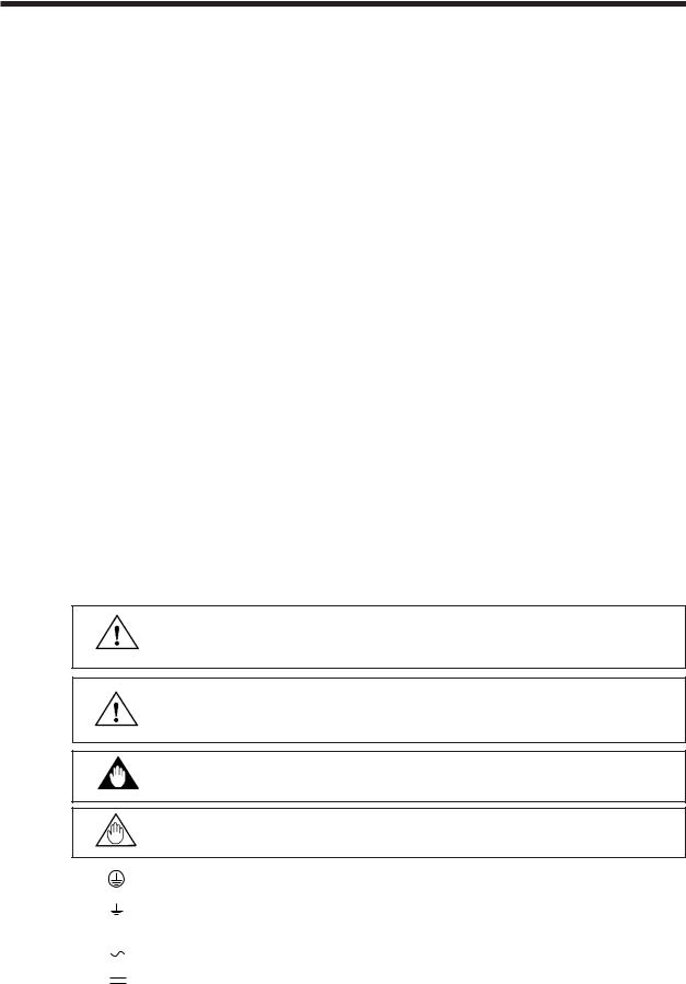
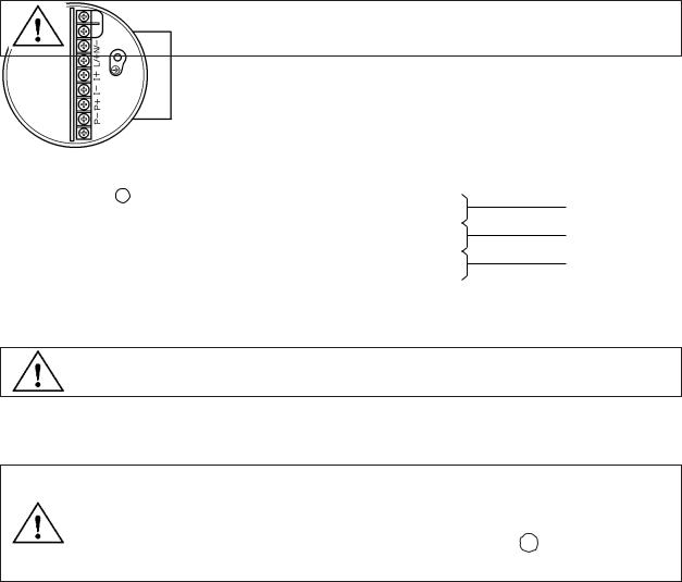
The following symbol marks are used in this manual and instrument;
A WARNING sign denotes a hazard. It calls attention to procedure, practice, condition or the like, which, if not correctly performed or adhered to, could result in injury or death of personnel.
A CAUTION sign denotes a hazard. It calls attention to procedure, practice, condition or the like, which, if not correctly performed or adhered to, could result in damage to or destruction of part or all of the product.
A IMPORTANT sign denotes an attention to avoid leading to damage to instrument or system failure.
A NOTE sign denotes a information for essential understanding of the operation and features.
Protective grounding terminal.
Function grounding terminal. This terminal should not be used as a “Protective grounding terminal”.
Alternating current.
Direct current.
1-1

• Warranty
*The guaranteed term of this instrument is described in the quotation. We repair the damages that occurred during the guaranteed term for free.
*Please contact with our sales office when this instrument is damaged.
*If the instrument has trouble, please inform us model code, serial number, and concrete substances or situations. It is preferable to be attached a outline or data.
*We decide after the examination if free repair is available or not.
*Please consent to the followings for causes of damages that are not available as free repair, even if it occured during the guaranteed term.
A : Unsuitable or insufficient maintenance by the customer.
B : The handling, using, or storage that ignore the design and specifications of the instrument.
C : Unsuitable location that ignore the description in this manual. D : Remaking or repair by a person except whom we entrust.
E : Unsuitable removing after delivered.
F : A natural disaster (ex. a fire, earthquake, storm and flood, thunderbolt) and external causes.
For the safety using ;
•The Magnetic Flowmeter is a heavy instrument. Please give attention to prevent that persons are injured by carrying or installing. It is preferable for carrying the instrument to use a cart and be done by two or more persons.
•In wiring, please confirm voltages between the power supply and the instrument before connecting the power cables. And also, please comfirm that the cables are not powered before connecting.
•When removing the instrument from hazardous processes, avoid contact with the
WARNING |
fluid and the interior of the meter. |
•In case of Hazardous duty type instrument, further requirements and differences are described in chapter 13 "HAZARDOUS DUTY TYPE INSTRUMENT". The description in chapter 13 is prior to other description in this instruction manual. Further, in case of JIS flameproof type, please read “INSTALLATION AND OPERATING PRECAUTIONS FOR JIS FLAMEPROOF EQUIPMENT” at the end of this manual.
1-2 |
IM 1E8B0-01E |

2. HANDLING PRECAUTIONS
2.HANDLING PRECAUTIONS
This instrument has been already tested thoroughly at the factory. When the instrument is delivered,please check externals and make sure that no damage occurred during transportation.
In this chapter, handling precautions are described. Please read this chapter thoroughly at first. And please refer to the relative matter about other ones.
If you have any problems or questions, please make contact with Yokogawa sales office.
2.1 Checking Model and Specifications
The model and specifications are shown on the Data Plate of the flow converter. Please comfirm the specifications between the instrument that was delivered and the purchase order (refer to the section 10.4 Model and Suffix Code).
Please let us know Model and Serial No. when making contact with Yokogawa sales office.
|
|
|
MAGNETIC FLOWMETER |
|
|
MODEL |
|
|
PULSE |
|
|
SUFFIX |
|
|
OUTPUT |
30V DC 0.2 Amax. |
|
SIZE |
|
|
LINING |
CERAMICS |
|
STYLE |
|
|
MATERIAL |
|
|
mm |
|
|
|
||
SIZE |
|
CURRENT |
4 - 20mA |
|
|
METER |
|
|
OUTPUT |
(0 - 750Ω) |
°C |
FACTOR |
VDC |
13W |
FLUID TEMP. |
–10~120 |
|
SUPPLY |
FLUID PRESS |
–0.1~ |
MPa |
||
|
VAC~47–63Hz 36VA 13W |
AMB. TEMP. |
–20~50 |
°C |
|
FULL SCALE |
|
No. |
|
|
|
Made In
Figure 2.1 Data Plate
2.2 Accessories
When the flowmeter is delivered, make sure that the following accessories are in the package. Spare fuse can be applied only to this product.
•Fuse (250 V, 2 A time lag) (the spare fuse is taped to the converter) (1-piece)
•Data sheet (1-sheet)
•Unit labels (1-sheet)
•Centering device (1-set)
•Plug (for DC power supply only) (1-piece)
•Hexagonal Wrench (only for hazardous duty type instrument) (1-piece)
IM 1E8B0-01E |
2-1 |
2. HANDLING PRECAUTIONS
2.3 Storage Precautions
In case the instrument is expected to be stored over a long term, please give attention to the followings ;
*The instrument should be stored in its original packing condition.
*The storage location should be selected according to the following conditions:
1)The location where it is not exposed to rain or water.
2)The location where there is few vibration or shock.
3)Temperature and humidity should be:
Temperature : -20 to 50˚C (-4 to 122˚F)
Humidity : 5 to 80% RH (no condensation)
Preferable ambient temperature and humidity are 25˚C(75˚F) and about 65%
RH.
2.4 Installation Location Precautions
|
Please select the installation location considering the following items to ensure long term |
|
stable operation of the flowmeter. |
• Ambient Temperature |
: Please avoid to install the instrument at the location where temperature changes |
|
continuously. If the location receives radiant heat from the plant, provide heat insulation |
|
or improve ventilation. |
• Atmospheric Condition |
: Please avoid to install the instrument in an corrosive atmosphere. In case of installing |
|
in the corrosive atmosphere, please keep ventilating sufficiently and prevent rain from |
|
entering the conduit. |
• Vibration or Shock |
: Please avoid to install the instrument at the location where there is heavy vibration or |
|
shock. |
2.5 Converter Reorientation Precautions
Please do not change the converter orientation at the customer’s site.
2-2 |
IM 1E8B0-01E |

3. COMPONENT NAMES
3.COMPONENT NAMES
Data Plate
Electrical Connection
Cover
Display |
Converter |
Flow Direction
Miniflange
Flow Tube
Earth ring
Size: 25 to 200mm (1 to 8 inch)
Size: 15 mm (0.5 inch)
IM 1E8B0-01E |
3-1 |
4.INSTALLATION
4. INSTALLATION
WARNING |
This instrument must be installed by expert engineer or skilled personnel. |
|
The procedures described in this chapter are not permitted for operators. |
||
|
4.1 Piping Design Precautions
 IMPORTANT Please design the correct piping referring to the followings to prevent damage for flowmeter and to keep correct measuring.
(1) Location
 IMPORTANT Please install the flowmeter to the location where it is not exposed to direct sunlight and ambient temperature is -20 to +50˚C (-4 to 122˚F) .
(2) Noise Rejection
• The instrument should be installed away from large electrical motors,
transformers and other power sources in order to avoid interference with IMPORTANT the measurement.
•In case several capacitance Magnetic Flowmeters are installed, please install them 1 m (40 in) or more apart.
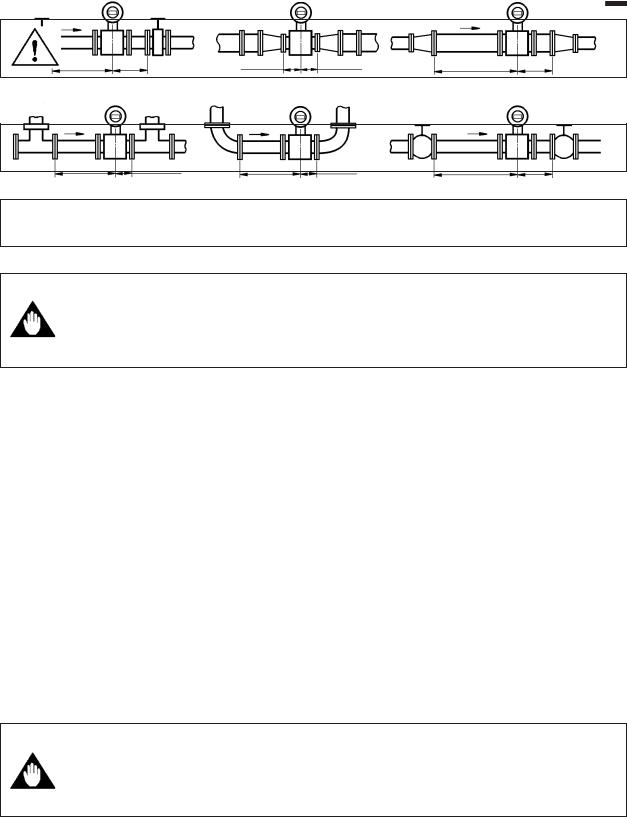
(3)Length of Straight Run
To keep accurate measuring, JIS B7554 “Electro Magnetic Flowmeters” explains about upstream piping condition of Magnetic Flowmeters.
We recommend to our customers about the piping conditions shown in Figure 4.1.1 based on JIS B7554 and our piping condition test data.
D:Internal diameter of flowmeter
Gate valve fully open |
Reducer pipe |
Expander pipe |
5D or more |
|
10D or more |
2D or more |
Do not care to 0D |
2D or more |
|
90 degrees bent |
Various type of valves |
Tee 5D or more |
Do not care to 0D 5D or more |
Do not care to 0D |
10D or more |
2D or more
Figure 4.1.1 Minimum Length of Required Straight Run
In the application for pure water, pure alcohol and other fluids which have low conductivity with low viscosity, we recommend the upper stream length
IMPORTANT of straight run of magmeter be 20D ( where D denotes size of flow tube) or more. Please be careful that gasket material dose not protrude in pipe inner surface.
Notes : 1. Nothing must be inserted or installed in the metering pipe that may interfere with the magnetic field, induced signal voltages, and flow velocity distribution.
2.These straight runs may not be required on the downstream side of the flowmeter. However, if the downstream valve or other fittings cause channeling on the upstream side, provide a straight run of 2 D to 3 D on the downstream side.
IM 1E8B0-01E |
4-1 |

4.INSTALLATION
(4)Applicable Velocity Range in Low Conductivity Fluid Measurement
•In the application for pure water, pure alcohol and other fluids which have low conductivity with low viscosity, fluid velocity should be within the
IMPORTANT |
range of Applicable velocity range which is shown in the figure listed |
|
below depending on fluid conductivity. |
||
|
•The fluid that cause phase separation and has higher fluid conductivity around the inner surface of the flowtube cannot be measured.
Size 15 to 100mm (0.5 to 4 in)
|
10(30) |
|
|
|
9 |
|
|
|
8 |
|
|
Flow |
7 |
|
|
6 |
|
|
|
Velocity |
|
|
|
m/s (ft/s) |
5(15) |
|
|
|
4 |
|
|
|
3 |
|
|
|
2 |
|
Application Velocity |
|
1 |
|
Range |
|
|
|
|
|
0 |
1 |
10 |
|
0.1 |
||
|
|
|
Conductivity S/cm |
|
|
Size 150, 200mm (6, 8 in) |
|
|
10(30) |
|
|
|
9 |
|
|
|
8 |
|
|
Flow |
7 |
|
|
6 |
|
|
|
Velocity |
|
|
|
m/s (ft/s) 5(15) |
|
|
|
|
4 |
|
|
|
3 |
|
Application Velocity |
|
2 |
|
Range |
|
|
|
|
|
1 |
|
|
|
0 |
10 |
100 |
|
1 |
||
|
|
|
Conductivity S/cm |
(5) Liquid Conductivity
Please avoid to install the flowmeter at location where liquid conductivity is likely to be non-uniform. Because it is possible to have bad influences to the flow indication by non-uniform conductivity when a chemical liquid is in-
IMPORTANT jected from upstream side close to the flowmeter. When this occurs, it is recommended that chemical application ports are installed on the downstream side of the flowmeter. In case chemicals must be added upstream side, please keep the pipe length enough so that liquid is properly mixed.
(BAD) |
(GOOD) |
Upstream side |
Downstream side |
4-2 |
IM 1E8B0-01E |

4.INSTALLATION
(6) Liquid Sealing Compound
Please give attention in using Liquid Sealing Compound to the piping, IMPORTANT because it brings bad influences to measurement by flowing out and cover
the surfaces of earth-ring.
(7) Service Area
Please select the location where there is enough area to service installing, wiring, overhaul,etc.
(8) Bypass Line
It is recommended to install the Bypass Line to facilitate maintenance and zero adjustment.
Bypass valve
Block valve
Block valve
(9) Supporting the Flowmeter
Please avoid to support only the flowmeter, but fix pipes at first and support CAUTION the flowmeter by pipes to protect the flowmeter from forces caused by
vibration,shock, expansion and contraction through piping.
(10)Piping Condition
The piping should be designed so that a full pipe is maintained at all times IMPORTANT to prevent loss of signal and erroneous reading.
Please design the piping that a fluid is always filled in the pipes. The Vertical Mounting is effective for fluids that is easily separate or slurry settles within pipes.
In this case, please flow a fluid from bottom to up.
(GOOD) |
(BAD) |
(GOOD) |
(BAD) |
|
|
|
h |
|
|
|
h > 0 |
|
h |
|
|
|
h > 0 |
|
|
|
Horizontal mounting |
|
Vertical mounting |
IM 1E8B0-01E |
4-3 |
4.INSTALLATION
(11)No Air Bubbles
IMPORTANT Please give attention to prevent bad influences or measuring errors from air bubbles that gathers inside measuring pipes.
In case the fluid includes air bubbles, please design the piping that prevent to gather air bubbles. In case valves are installed upstream of the flowmeter, it is possible that a valve causes air bubbles, please install the flowmeter upstream side of a valve.
|
(GOOD) |
(GOOD) |
(BAD) |
|
(BAD) |
|
|
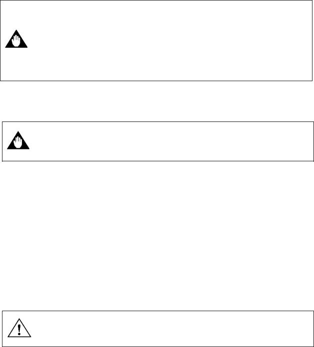
(12)Mounting Direction |
|
|
|
|
|
||
|
When the electrodes are vertical to ground, the electrode is covered with air |
||
|
bubbles at upper side or slurry at downside, and it may causes the measur- |
||
IMPORTANT ing errors. |
|
|
|
|
Please be sure to mount the converter upperside of piping to prevent water |
||
|
penetration into converter case. |
|
|
|
|
|
|
(Good) |
(No Good) |
(No Good) |
|
Water slowly percolates downward through converter
Electrodes
Slurry Electrodes
Figure 4.1.6 Mounting Direction
4-4 |
IM 1E8B0-01E |

4.INSTALLATION
(13)Grounding
IMPORTANT Improper grounding can have an adverse affect on the flow measurement. Please ensure that the instrument is properly grounded.
The electromotive force of the magnetic flowmeter is minute and it is easy to be affected by noise. And also that reference electric potential is the same as the measuring fluid potential. Therefore, the reference electric potential (terminal potential) of the Flow Tube and the Converter/Amplifier also need to be the same as the measuring fluid. And moreover, that the potential must be the same with ground.
Please be sure to grounding according to Figure 4.1.7.
600 V vinyl insulated electric cable (2mm2 or larger)
Note: See “4.4.1 Protective Grounding” for information on protective grounding.
ring
Grounding resistance: 100Ω or less
(10Ω or less for TIIS(JIS) Flameproof type)
Figure 4.1.7 Gounding
IM 1E8B0-01E |
4-5 |

4.INSTALLATION
4.2 Mounting Precautions
WARNING The Magnetic Flowmeter is a heavy instrument. Please be careful to prevent persons from injuring when it is handled.
4.2.1 General Precautions
(1) Precaution for Carrying
The Magnetic Flowmeter is packed tightly. When it is unpacked, please give attention to prevent damages to the flowmeter. And to prevent the accident during carry to the installing location, please carry it near the location keeping packed as it delivered.
In case the Magnetic Flowmeter size 150, 200 mm (6, 8 CAUTION inch) lifts up, please refer to Figure 4.2.1. Please never
lift up by using a bar through the flow tube.
Figure 4.2.1 Lifting Method
(2) Precaution for Shock
Care should be taken not to drop the flowmeter or subject it to excessive
CAUTION shock.
(3) Precaution for Terminal Box Covers
 IMPORTANT Please never leave the terminal box cover open until wiring to prevent insulation deterioration.
(4) Precaution for Long-Term Non-Use
It is not preferable to leave the flowmeter for long term non-use after installation.
In case the flowmeter is compelled to do that, please take care of the flowmeter by the followings.
*Confirmation of Sealing Condition for the Flowmeter
Please confirm the sealing conditions of the terminal box screw and wiring
IMPORTANT |
ports. |
|
In case of the Conduit Piping, please provide the drain plugs or water- |
|
proof glands to it to prevent that moisture or water penetrates into the flow |
|
tube through the conduit. |
*Regular Inspections
Please inspect the sealing condition (as above mentioned) and inside of the terminal box. And when it is suspect that water penetration into the inside detector (ex. rain fall), please inspect when it happened.
4-6 |
IM 1E8B0-01E |

4.INSTALLATION
4.2.2 Flowmeter piping
CAUTION Mis-aligned or slanted piping can lead to leakage and damage to flanges.
Please be sure the inner diameter of the gasket between ADMAG CA and IMPORTANT piping flange does not protrude to inner piping. It can lead to error in
measurement. This is important especially for low conductivity fluid.
•Please correct mis-alignment or slanted piping and improper distance between mounting flanges before install the flowmeter. (Please refer to Figure 4.2.2)
•Inside a pipeline which is newly installed, some foreign substances (such as welding scrap or wood chips) may exist. Please remove them by flushing piping before mounting flow tube.
slant
Figure 4.2.2 Slant and Mis-alignment of Flowmeter Piping
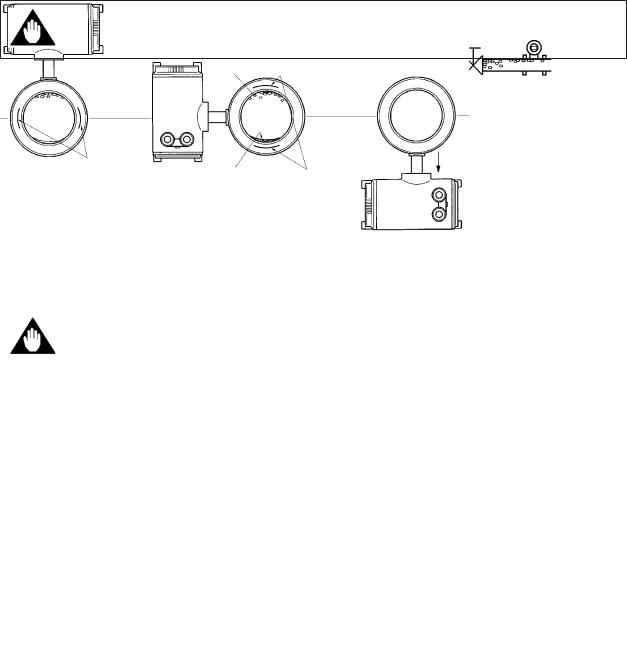
4.2.3 Alteration of LCD Display Orientation
LCD display orientation can be altered according to piping configurations if horizontal or vertical, just by removing four screws, adjusting unit orientation and fixing the screws tightly again as shown in Figure 4.2.3.
Figure 4.2.3 Procedure of Altering LCD Display Orientation
NOTE |
Orientation of display unit is limited to the two positions shown in this figure. |
|
|
IM 1E8B0-01E |
4-7 |
4.INSTALLATION
4.3 Mounting
4.3.1 Nominal Diameter 15mm (0.5") to 40 mm (1.5")
Please use appropriate bolts and nuts according to process connection. In case stud type of through bolts are used, be sure outside diameter of a shank is smaller than a thread ridge's one.
IMPORTANT Please use compressed non-asbestos fiber gasket, PTFE gasket or the gasket which has equal elasticity. In case of optional code/FRG, please
use rubber gasket or others which has equal elasticity. Be sure the inner diameter of the gasket does not protrude to inner piping. (Refer to Table 4.3.6)
A: Mounting Direction
Please mount the Magnetic Flowmeter matching the flow direction to be measured with the direction of the arrow mark on the flowmeter.
If it is impossible to match the direction, please never remodel by changing IMPORTANT direction of the converter. In case the measuring fluid flows against the
arrow direction, please refer to the section 6.4.6 Reversing Flow Direction.
B: Mounting Centering Devices
To keep concentricity of the Flow Tube with pipes, please mount centering devices on the Mini-Flanges of the Flow Tube.
Please give attention to the nominal diameter and flange ratings of the centering devices.
C: Positioning Flow Tube
Please pass two through-bolts to lower adjacent holes of both flanges and mount the Flow Tube, and pass other through-bolts to other holes. (Refer to Figure 4.3.1 / 4.3.2) In case stud type of through-bolts are used, position them coming in contact centering devices with thread of bolts.
D: Tightening Nuts
Please tighten the bolts according to Torque Values in Table 4.3.1. In case of PVC piping, please select optional code /FRG, use rubber gasket and tighten with the torque value in Table 4.3.2.
Please be sure to tighten the bolts following prescribed torque values. CAUTION Please tighten the flange bolts diagonally with the same torque values, step
by step up to the prescribed torque value.
4-8 |
IM 1E8B0-01E |

4.INSTALLATION
bolts
Vertical Mounting |
Horizontal Mounting |
Figure 4.3.1 Mounting Procedure (15mm (0.5”))
bolts
Vertical Mounting |
Horizontal Mounting |
Figure 4.3.2 Mounting Procedure (25(1˝), 40mm (1.5˝))
IM 1E8B0-01E |
4-9 |

4.INSTALLATION
Table 4.3.1 Maximum Tightening Torque Values for Metal Piping N·m {kgf·cm} [in-lbf]
|
Flange |
|
JIS |
|
ANSI |
DIN |
|
Size |
Rating |
|
|
||||
10K |
20K |
150 |
300 |
PN 10/16 |
|||
mm(inch) |
|||||||
|
15(0.5) |
14{143}[124] |
14{143}[124] |
14{143}[124] |
14{143}[124] |
14{143}[124] |
|
|
25(1) |
30{306}[265] |
30{306}[265] |
22{224}[195] |
30{306}[265] |
25{255}[221] |
|
|
40(1.5) |
44{449}[389] |
44{449}[389] |
33{337}[292] |
51{520}[451] |
50{510}[442] |
|
* Please use compressed non-asbestos fiber gasket, PTFE gasket or the gasket which has equal elasticity.
Table 4.3.2 Maximum Tightening Torque Values for PVC Piping N·m {kgf·cm} [in-lbf]
|
Flange |
|
|
JIS |
|
ANSI |
|
DIN |
||
Size |
Rating |
|
|
|
|
|||||
|
|
|
|
|
|
|
|
|
||
mm(inch) |
|
10K |
|
20K |
150 |
|
300 |
|
PN 10/16 |
|
|
|
|
|
|
|
|
|
|
|
|
|
15(0.5) |
|
1.3{13}[12] |
|
— |
1.3{13}[12] |
|
— |
|
1.3{13}[12] |
|
|
|
|
|
|
|
|
|
|
|
|
25(1) |
|
3.5{36}[31] |
|
— |
2.8{29}[25] |
|
— |
|
2.7{28}[24] |
|
|
|
|
|
|
|
|
|
|
|
|
40(1.5) |
|
5.7{58}[50} |
|
— |
4.6{47}[41] |
|
— |
|
5.7{58}[50} |
|
|
|
|
|
|
|
|
|
||
|
* |
Please select optional code /FRG and use rubber gasket or others which has equal elasticity. |
|
|||||||
4-10 |
IM 1E8B0-01E |

4.INSTALLATION
4.3.2 Nominal Diameter 50mm (2˝) to 200 m (8˝)
Please use appropriate bolts and nuts according to process connection. In case stud type of through bolts are used, be sure outside diameter of a
shank is smaller than a thread ridge's one.
IMPORTANT Please use compressed non-asbestos fiber gasket, PTFE gasket or the gasket which has equal elasticity. In case of optional code/FRG, please use rubber gasket or others which has equal elasticity. Be sure the inner diameter of the gasket does not protrude to inner piping. (Refer to Table 4.3.6)
A : Mounting Direction
Please mount the Magnetic Flowmeter matching the flow direction of the fluid to be measured with the direction of the arrow mark on the flowmeter.
If it is impossible to macth the direction, please never remodel to change IMPORTANT direction of the converter. In case the measuring fluid flows against the
arrow direction, please refer to the section 6.4.6 Reversing Flow Direction.
B : Mounting Centering Devices
To keep concentricity between the Flow Tube and pipes, centering devices must be used. Pass two through-bolts through the four centering devices (two for each) and lower adjacent holes of both flanges. (Refer to Figure 4.3.3)
Please give attention to the nominal size and flange ratings of the centering devices. (Refer to Table 4.3.5)
C : Positioning Flow Tube
Position the Flow Tube coming in contact four centering devices with Mini-Flanges.
At this time, pay attention to avoid four centering devices come in contact with Housing. In case stud type of through-bolts are used, position them coming in contact four centering devices with thread of the bolts. (Refer to Figure 4.3.3)
After positioning the Flow Tube, pass remaining through-bolts to remaining holes.
D : Tightening Nuts
Please tighten the bolts according to Torque Values in Table 4.3.3. In case of PVC piping, please select optional code /FRG, use rubber gasket and tighten with the torque value in Table 4.3.4.
Please be sure to tighten the bolts following prescribed torque values.
CAUTION Please tighten the flange bolts diagonally with the same torque values, step by step up to the prescribed torque value.
IM 1E8B0-01E |
4-11 |
4.INSTALLATION
Nuts
Through bolts
Mini-Flange
Gaskets
Flange
Please use appropriate |
|
bolts and nuts according to |
Centering devices (four) |
process connection. |
Housing |
|
Horizontal Mounting Vertical Mounting
|
Figure 4.3.3 |
Mounting Procedure |
|
|
|
|
|||
|
Table 4.3.3 |
Maximum Torque Value for Metal Piping N·m {kgf·cm} [in-lbf] |
|||||||
|
|
|
|
|
|
|
|
|
|
Flange |
JIS |
|
ANSI |
DIN |
|
||||
Rating |
|
JIS G3451 |
|||||||
|
|
|
|
|
|
|
|
||
Size |
10K |
|
20K |
150 |
|
300 |
PN 10 |
PN 16 |
F12(75M) |
mm(inch) |
|
|
|||||||
|
|
|
|
|
|
|
|
|
|
|
|
|
|
|
|
|
|
|
|
50(2) |
50{510}[442] |
27{276}[239] |
50{510}[442] |
|
27{276}[239] |
— |
63{643}[558] |
— |
|
|
|
|
|
|
|
|
|
|
|
80(3) |
36{367}[319] |
44{449}[389] |
75{765}[664] |
|
44{449}[389] |
— |
36{367}[319] |
80{816}[708] |
|
|
|
|
|
|
|
|
|
|
|
100(4) |
48{490}[425] |
58{592}[513] |
49{500}[434] |
|
56{571}[496] |
— |
48{490}[425] |
105{1071}[929] |
|
|
|
|
|
|
|
|
|
|
|
150(6) |
79{806}[699] |
55{561}[487] |
66{673}[584] |
|
43{439}[381] |
— |
76{776}[673] |
84{857}[743] |
|
|
|
|
|
|
|
|
|
|
|
200(8) |
70{714}[619] |
76{776}[673] |
102{1041}[903] |
|
76{776}[673] |
103{1051}[911] |
67{684}[593] |
102{1041}[903] |
|
|
|
|
|
|
|
|
|
||
|
* Please use compressed non-asbestos fiber gasket, PTFE gasket or the gasket which has equal elasticity. |
||||||||
|
Table 4.3.4 |
Maximum Torque Value for PVC Piping N·m {kgf·cm} [in-lbf] |
||||||||
|
|
|
|
|
|
|
|
|
|
|
Flange |
JIS |
|
ANSI |
|
|
DIN |
|
|||
Rating |
|
|
|
JIS G3451 |
||||||
|
|
|
|
|
|
|
|
|
||
Size |
10K |
|
20K |
150 |
|
300 |
PN 10 |
|
PN 16 |
F12(75M) |
mm(inch) |
|
|
|
|||||||
|
|
|
|
|
|
|
|
|
|
|
|
|
|
|
|
|
|
|
|
|
|
50(2) |
8.2{84}[73] |
|
— |
8.2{84}[73] |
|
— |
— |
|
8.2{84}[73] |
— |
|
|
|
|
|
|
|
|
|
|
|
80(3) |
6.2{63}[55] |
|
— |
12.4{127}[110] |
|
— |
— |
|
6.2{63}[55] |
12.3{126}[109] |
|
|
|
|
|
|
|
|
|
|
|
100(4) |
8.0{82}[71] |
|
— |
8.1{83}[72] |
|
— |
— |
|
8.0{82}[71] |
16.1{164}[142] |
|
|
|
|
|
|
|
|
|
|
|
150(6) |
19.8{202}[175] |
|
— |
18.9{193}[167] |
|
— |
19.8{202}[175] |
19.8{202}[175] |
21.6{220}[191] |
|
|
|
|
|
|
|
|
|
|
|
|
200(8) |
17.5{179}[155] |
|
— |
25.1{256}[222] |
|
— |
26.2{267}[232] |
17.5{179}[155] |
28.7{293}[254] |
|
|
|
|
|
|
|
|
|
|||
|
* Please select optional code /FRG and use rubber gasket or others which has equal elasticity. |
|
||||||||
4-12 |
IM 1E8B0-01E |

|
|
|
|
|
|
|
|
|
|
|
|
|
4.INSTALLATION |
|
|
Table 4.3.5 |
Centering Device Identification |
|
|
|
|
|
|
||||||
|
|
|
|
|
|
|
|
|
|
|
|
|
|
|
|
Flange |
|
|
|
|
JIS G3451 |
|
|
|
|
|
|
DIN PN |
|
Size |
Rating |
JIS 10K |
JIS 20K |
|
ANSI 150 |
|
ANSI300 |
|
||||||
F12 |
|
|
|
10/16 |
||||||||||
mm(inch) |
|
|
|
|
|
|
|
|
|
|
||||
|
|
|
|
|
|
|
|
|
|
|
|
|||
|
|
|
|
|
|
|
|
|
|
|
|
|
|
|
|
50(2) |
B |
|
|
B |
- |
|
|
B |
|
F |
|
F |
|
|
|
|
|
|
|
|
|
|
|
|
|
|
|
|
|
80(3) |
B |
|
|
F |
H |
|
|
F |
|
C |
|
G |
|
|
|
|
|
|
|
|
|
|
|
|
|
|
|
|
|
100(4) |
B |
|
|
F |
H |
|
|
C |
|
H |
|
F |
|
|
|
|
|
|
|
|
|
|
|
|
|
|
|
|
|
150(6) |
B |
|
|
C |
G |
|
|
B |
|
D |
|
B |
|
|
|
|
|
|
|
|
|
|
|
|
|
|
|
|
200(18) |
B |
|
|
C |
C |
|
|
G |
|
J |
|
B |
||
|
|
|
|
|
|
|
|
|
|
|
|
|
||
|
|
|
* Each Centering Devices is engraved a character as identification. |
|
|
|
||||||||
|
Table 4.3.6 |
Earth Ring Inside Diameter |
|
|
|
|
|
|
||||||
|
|
|
|
|
|
|
Unit: mm(inch) |
|
|
|
||||
|
|
|
Size |
|
|
Earth Ring Inside Diameter |
|
|
|
|
|
|
||
|
|
|
|
|
|
|
|
|
|
|
|
|
|
|
|
|
|
15(0.5) |
|
|
|
ø15(0.6) |
|
|
|
|
|
|
|
|
|
|
|
|
|
|
|
|
|
|
|
|
|
|
|
|
|
25(1) |
|
|
|
ø27(1.1) |
|
|
|
|
|
|
|
|
|
|
|
|
|
|
|
|
|
|
|
|
|
|
|
|
|
40(1.5) |
|
|
|
ø40(1.6) |
|
|
|
|
|
|
|
|
|
|
|
|
|
|
|
|
|
|
|
|
|
|
|
|
|
50(2) |
|
|
|
ø52(2.1) |
|
|
|
|
|
|
|
|
|
|
|
|
|
|
|
|
|
|
|
|
|
|
|
|
|
80(3) |
|
|
|
ø81(3.2) |
|
|
|
|
|
|
|
|
|
|
|
|
|
|
|
|
|
|
|
|
|
|
|
|
|
100(4) |
|
|
|
ø98(3.9) |
|
|
|
|
|
|
|
|
|
|
|
|
|
|
|
|
|
|
|
|
|
|
|
|
|
150(6) |
|
|
|
ø144(5.7) |
|
|
|
|
|
|
|
|
|
|
|
|
|
|
|
|
|
|
|
|
|
|
|
|
|
200(8) |
|
|
|
ø192(7.6) |
|
|
|
|
|
|
|
* Please be sure the inner diameter of a gasket does not protrude to the each ring inside diameter.
IM 1E8B0-01E |
4-13 |
4.INSTALLATION
4.4 Wiring
CAUTION
Confirm that all connections are correct before applying power to the instrument. Improper wiring may damage the flowmeter.
The external signal wirings are connected into the terminal inside the converter. Please connect to each terminal (Please refer to Figure 4.4.1) by taking off a cover backside the converter.
Terminal Symbols |
|
|
Description |
|
||
|
|
|
|
|
||
|
|
|
Protective grounding |
|
||
N– |
|
|
Power Supply |
|
|
Power supply |
|
|
|
||||
L+ |
|
|
|
|||
|
|
|
|
|
Protective grounding |
|
|
|
|
|
|||
I+ |
|
|
Current Output 4 to 20mA DC |
|
|
4 to 20 mA DC output |
|
|
|
||||
I– |
|
|
|
|||
|
|
|
|
|
Pulse or alarm |
|
P+ |
|
|
Pulse or alarm output |
|
|
|
P– |
|
|
|
|||
|
|
|
|
|
|
|
|
|
|
|
|
|
|
Figure 4.4.1 Terminal
CAUTION Please give attention to avoid the cable is bended excessively.
4.4.1 Protective Grounding
Please be sure to connect protective grounding of ADMAG CA with cable of 2mm2 or larger cross section in order to avoid the electrical shock to the
CAUTION operators and maintenance engineers and prevent the influence of external noise. And further connect the grounding wire to the  mark (100Ω or less).
4-14 |
IM 1E8B0-01E |

4.INSTALLATION
4.4.2 General Precautions
Observe the following when wiring ;
(1) Do not connect cables outside when it is raining, to ensure insulation within the terminal box of the meter tube and to prevent failure due to moisture.
(2) Power cables and signal wire ends are to be provided with round crimpon terminal.
(3) Power cables and output signal cables must be routed in steel conduit tubes separately.(except 4-core DC cable wiring)
(4) When waterproof glands, union equipped waterproof glands are used,
CAUTION |
the glands must be properly tightened to keep the box watertight. |
|
(5)Please install a external switch or circuit breaker as a means of power off (capacitance:15A, conform to IEC 947-1 and IEC 947-3). The preferable location is either near the instrument or other places to easy operation. Furthermore, please indicate “power off equipment” on the those external switch or circuit breaker.
(6)Please be sure to fully tighten the covers before the power is turned on.
(7)Please be sure to turn off the power before opening the covers.
(8)In case of DC Power Supply, a plug is attached. When 4-core cable is used, please put that plug into unused electrical connection port.
4.4.3Power and Output Cables
Power cable |
* Crimp-on Terminal |
|
* 60˚C heat resistance |
|
* Green/Yellow covered conductors shall be used only for connection to PROTECTIVE |
|
CONDUCTOR TERMINALS. |
|
* Conform to IEC 227 or IEC245 or equivalent national authorization. |
Output Cable |
• Please use Polyvinyl chloride insulated and sheathed control cables (JIS C3401) or |
|
Polyvinyl chloride insulated and sheathed portable power cables (JIS C3312) or |
|
equivalents. |
Outer Diameter |
• 6.5 to 12mm in diameter (10.5 or 11.5mm for waterproof gland/ ECG, /ECU) |
Nominal Cross Section |
• Single wire ; 0.5 to 2.5mm2 , Stranded wire ; 0.5 to 2.5mm2 |
IM 1E8B0-01E |
4-15 |
4.INSTALLATION
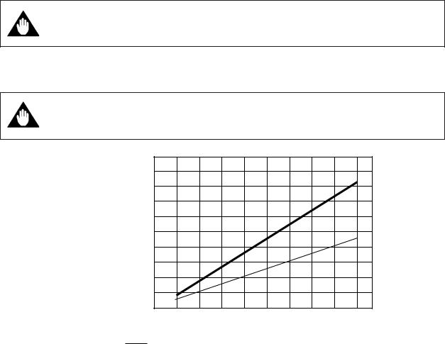
4.4.4 DC Connections
(1) Connecting Power Supply
• In case of 24V DC power supply, AC power supplies or reversed polarities IMPORTANT cannot be connected.
It will cause the fuse to burnout.
(2) Supply Voltage Rating
• In case of 24V DC power supply, the specification for the supply voltage IMPORTANT is 24V DC (-15% to +20%), but the input voltage of the converter drops
due to cable resistance so it should be used within the following range.
Supply Voltage and Cable Length
|
1000 |
|
|
|
|
|
(3300) |
|
|
|
|
|
900 |
|
|
|
|
|
(2970) |
|
|
|
|
|
800 |
|
|
|
|
|
(2640) |
|
|
|
|
|
700 |
|
|
|
|
|
(2310) |
|
|
|
|
Allowed |
600 |
|
|
|
|
cable |
(1980) |
|
|
|
|
length |
500 |
|
|
|
|
(1650) |
|
|
|
|
|
m(ft) |
400 |
|
|
|
|
|
(1320) |
|
|
|
|
|
300 |
|
|
|
|
|
(990) |
|
|
|
|
|
200 |
|
|
|
|
|
(660) |
|
|
|
|
|
100 |
|
|
|
|
|
(330) |
|
|
|
|
|
0 |
22 |
24 |
26 |
28 |
|
20 |
||||
|
|
|
Usable range E(V) |
|
|
Cable cross section area : 1.25mm2 |
|
Cable cross section area : 2mm2 |
|
4-16 |
IM 1E8B0-01E |

4.INSTALLATION
4.4.5 Wiring Ports
Please select the most suitable standard of wiring procedure for the wiring ports by customer’s own.
This instrument is of watertight construction as stipulated in JIS C0920 (Tests to prove protection against ingress of water and degrees of protection against ingress of solid objects for electrical equipment.) It is shipped with a wiring bracket (waterproof gland or waterproof gland with union) or a plastic gland attached, only in cases where an optional specification is selected for the wiring port.
In case of the explosion proof type, refer to chapter 13.
The wiring port is sealed with a cap (not water-proof). Do not remove the IMPORTANT cap from the unused wiring port. If waterproof property is necessary, please
use waterproof glands.
(1) When waterproof property is unnecessary
(When there are no particular optional specifications)
The wiring port is sealed with a cap (not water-proof) that must be removed before wiring. At this time, handle the wiring port in accordance with the JIS C0920 mentioned above. Do not remove the cap from the unused wiring port.
(2)When waterproof property is necessary (Wiring using waterproof glands)
To prevent water or condensate from entering the converter housing, water
IMPORTANT proof glands are recommended. Do not over-tighten the glands or damage to the cables may result. Tighteness of the gland can be checked by
confirming that the cable is held firmly in place.
Waterproof gland |
Waterproof gland with union |
Optional specification |
joint Optional specification |
code: / ECG |
code: / ECU |
Gasket |
G 1/2 |
|
Tightening gland
Gasket
Tightening gland
G 1/2
(PF 1/2 internal thread)
IM 1E8B0-01E
Figure 4.4.2 Waterproof Gland
4-17

4.INSTALLATION
(3) Conduit Wiring
In case of conduit wiring, please use the waterproof gland to prevent water flowing through the conduit pipe into the wiring connection.
Please slope the conduit pipe down, and install a drain valve at the low end of the vertical pipe.
Please open the drain valve regularly.
Figure 4.4.3 Conduit Piping
4-18 |
IM 1E8B0-01E |
4.INSTALLATION
4.4.6 Connecting to External Instruments
CAUTION
All the devices to be connected to current output and pulse output must be conformed to CSA1010, CSA950, IEC1010 or IEC950.
(1) Analog Signal Output (4 to 20mA DC signal is output)
ADMAG CA |
Receiving instrument |
|
|
Load resistance max 750Ω |
|
|
(max 600Ω for BRAIN |
|
|
Communication) |
|
Figure 4.4.4 Connection for Analog Signal Output
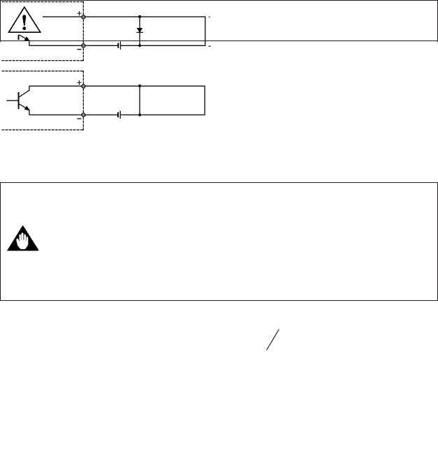
(2) Pulse Output
This is a transistor contact (insulated type) so attention must be paid to voltage and polarity when making connections.
• |
In case of the constant of inputfilter of Electric Counter is more than the |
IMPORTANT |
pulse width, it makes signal decreases and can't calculate correctly. |
• In case of input impedance of Electric Counter is large, inductive noise from power supply bring bad influence to it. To calculate correctly, it is recommended to use sealed cable or to make input impedance small enough within the limits of pulse output of Magnetic Flowmeter.
Protective diode
P+
ADMAG CA
PULSE OUT |
Mechanical counter |
|
|
P–
P+
ADMAG CA
PULSE OUT |
Load |
|
Universal counter or Electronic counter |
|
|
|
|
P–
30 V DC, 0.2A max.
Figure 4.4.5 Pulse Output Connection
IM 1E8B0-01E |
4-19 |

4.INSTALLATION
(3) Alarm Output
|
This is a transistor contact (insulated type) so attention must be paid to |
||||
IMPORTANT |
voltage and polarity when making connections. |
||||
|
This output cannot switch an AC load. To do this a special relay (refer to |
||||
|
the figure) is required. |
* The alarm output is normally closed. |
|||
|
|
|
|
|
|
ADMAG CA |
P+ |
|
|
|
|
|
|
|
Protective diode |
||
|
|
|
Load |
||
|
|
P– |
|
|
|
|
|
|
This connection cannot be made. |
||
ADMAG CA |
P+ |
|
|
|
|
|
|
|
|
|
|
|
|
|
|
Magnetic |
|
|
|
|
|
valve |
|
|
|
P– |
AC power supply |
||
|
|
|
|||
|
|
30 V DC, 0.2A max. |
|
|
|
Figure 4.4.6 Alarm Output Connection
4-20 |
IM 1E8B0-01E |

5. BASIC OPERATING PROCEDURES
5.BASIC OPERATING PROCEDURES
All data settings can be performed with the three keys on the front panel (SET, SHIFT and INC) or using a handheld BRAIN (BT) terminal.
The following sections describe basic data configurations and how to use the three panel keys. (See Chapter 7 for information on BT operations.)
5.1 Liquid Crystal Display
Figure 5.1 shows the configuration of the ADMAG CA display panel (if equipped).
(Note: The figure shows display when fully lit)
|
(1) LED (red) |
|
Normal operation: off |
|
|
During alarm: |
flashes |
|
(2) Delimiter |
|
|
(3) Unit Display |
l gal m3 /h /m |
|
Units displayed: |
SET SHIFT INC |
|
l: |
liters |
|
gal: |
gallon |
|
m3: |
cubic meters |
|
/h: |
hours |
|
/m: |
minutes |
|
|
If other units are to be used, attach |
|
|
labels giving the specific unit. |
|
(4)Unit Label Location
(5)Data Display
(6)Decimal Point
(7)Setting Key
Figure 5.1 Configuration of Display
(1) LED (red) |
: This LED is off during normal operation and flashes when |
|
an alarm condition has occurred. |
(2) Delimiter |
: The delimiter " : " (colon) indicates that the displayed data |
|
is in setting mode. |
(3) Unit Display |
: Displays flow rate units. In order to display other units, the |
|
required unit label should be selected from the provided |
|
data sheets and attached as shown. |
(4) Unit Label Location : To display units not on the LCD, select the required label
|
from the provided data sheets and attach it here. |
(5) Data Display |
: Displays flow rate data, setting data and type of alarm |
|
generated. |
(6)Decimal Point : Displays decimal point in the data.
(7)Setting Keys : These keys are used to change flow rate data displays and
type of setting data.
IM 1E8B0-01E |
5-1 |
Loading...