


User’s
Manual
Model CA51/71 HANDY CAL (Calibrator)
IM CA71-E
IM CA71-E 2nd Edition: Dec. 2006

Introduction
Thank you for purchasing the CA51/71 HANDY CAL Calibrator. This User’s Manual explains the functions of the CA51/71, as well as the operating methods and handling precautions. Before using the CA51/ 71, read this manual thoroughly to ensure correct use of the instrument. When you have finished reading this manual, store it in the carrying case for future reference.
■ Notes
●This manual exclusively describes the CA71, which is more multifunctional than the CA51. The CA51 has no temperature measurement and communication functions.
●The contents of this manual are subject to change without prior notice for reasons of improvements in performance and/or functionality.
●Every effort has been made to ensure the accuracy of this manual. If you notice any errors or have any questions, however, please contact the vender from which you purchased the instrument.
●The content of this manual may not be transcribed or reproduced, in part or in whole, without prior permission.
■ Trademark Acknowledgments
● All other company and product names appearing in this document are trademarks or registered trademarks of their respective holders.
■ Revision Information
February 2002: First edition December 2006: 2nd edition
Disk No. CA71-E
2nd Edition: Dec.2006
All Rights Reserved. Copyright © 2002, Yokogawa M&C Corporation
IM CA71-E
i
Checking Items in the Package
After opening the package, check the product as follows before use. If the delivered product is the wrong model, any item is missing, or there are visible defects, contact the vendor from which you purchased the product.
Main Unit
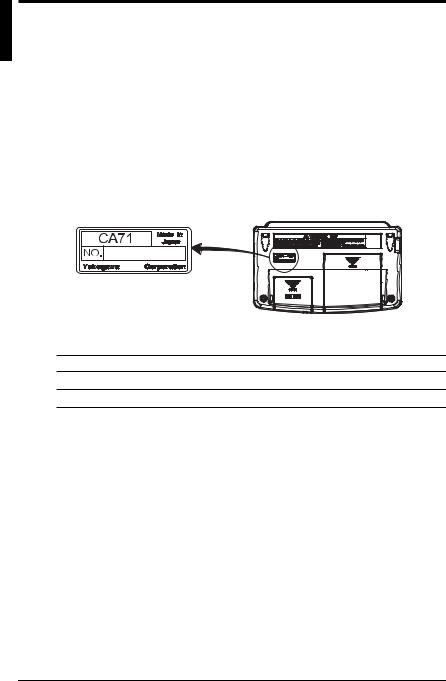
Check the model (specifications) codes in the MODEL and SUFFIX fields of the nameplate at the back of the instrument to ensure that the instrument is exactly as specified in your purchase order.
• Model Codes
Model Specification
CA51 Basic model
CA71 Provided with temperature measurement and communication functions
•NO. (Serial Number)
Refer to this serial number on the nameplate when contacting the vendor about the instrument.
ii
IM CA71-E
Checking Items in the Package
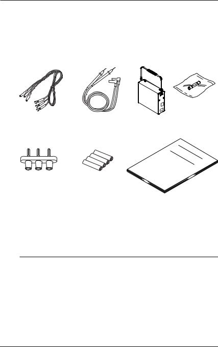
Standard Accessories
Make sure that the package contains all the accessories listed below and that they are all free from any damage.
Lead cables |
Lead cables for |
Carrying case |
Fuse |
for source |
measurement |
(93016) |
(A1501EF) |
(98020) |
(RD031) |
|
|
Terminal adapter |
AA-size (LR6) |
User’s manual |
(99021) |
alkaline batteries |
(IM CA71-E) |
|
(four units) |
|
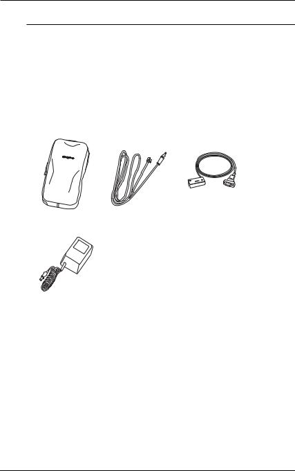
Optional Accessories
The products listed below are available as optional accessories. If you purchased some of the optional accessories, make sure the delivered package is complete with the ordered items and they are free from any damage. For technical and ordering inquiries concerning the accessories, contact the vendor from which you purchased the instrument.
Product |
Part Number |
Remarks |
AC adapter |
A1020UP |
For 100 V AC |
AC adapter |
A1022UP |
For 120 V AC |
AC adapter |
B9108WB |
For 220 to 240 V AC |
RJ sensor |
B9108WA |
For reference junction |
|
|
compensation |
Accessories case |
B9108XA |
|
Communication cable (RS232) |
91017 |
(For CA71 only) |
|
|
|
IM CA71-E |
iii |
Checking Items in the Package
Optional Spare Parts
Product |
Part Number |
Remarks |
|
Lead cable for source |
98020 |
|
|
Lead cable for measurement RD031 |
|
|
|
Carrying case |
93016 |
|
|
Terminal adapter |
99021 |
|
Used for temperature |
|
|
|
measurement |
Fuse |
A1501EF |
|
10 units as a kit |
|
|
|
|
Accessories case |
RJ sensor |
Communication cable |
|
AC adapter
iv
IM CA71-E
Precautions for Safe Use of the Instrument
For the correct and safe use of the instrument, be sure to follow the cautionary notes stated in this manual whenever handling the instrument. Yokogawa Meters & Instruments Corporation shall not be held liable for any damage resulting from use of the instrument in a manner other than prescribed in the cautionary notes.
The following symbols are used on the instrument and in the User’s Manual to ensure safe use.
Danger! Handle with Care.
This symbol indicates that the operator must refer to an explanation in the User’s Manual in order to avoid the risk of injury or loss of life of personnel or damage to the instrument.
This symbol indicates DC voltage/current.
This symbol indicates AC voltage/current.
This symbol indicates AC or DC voltage/current.
 WARNING
Indicates that there is a possibility of serious personal injury or loss of life if the operating procedure is not followed correctly and describes the precautions for avoiding such injury or loss of life.
 CAUTION
Indicates that there is a possibility of serious personal injury or damage to the instrument if the operating procedure is not followed correctly and describes the precautions for avoiding such injury or damage.
 NOTE
NOTE
Draws attention to information essential for understanding the operation and features.
IM CA71-E |
v |

Precautions for Safe Use of the Instrument
TIP
Provides additional information to complement the present topic.
Damage to the instrument or personal injury or even loss of life may result from electrical shock or other factors. To avoid this, follow the precautions below.
 WARNING
●Use in gases
Do not operate this instrument in areas where inflammable or explosive gases or vapor exists. It is extremely hazardous to use the instrument under such environments.
●Defects in protective features
Do not operate this instrument if any defect seems to exist in such protective features as fuses. Before operating the instrument, make sure the protective features are free from any defect.
●External connection
When connecting the instrument to the object under test or an external control circuit, or if you need to touch any external circuit, cut off the power to the circuit and make sure no voltage is being supplied.
●Fuses
In order to prevent a possible fire, use a fuse with ratings (current, voltage, and type) specified for the instrument. Do not short-circuit the fuse holder.
●Correctly use the lead cables for measurement (P/N: RD031) and source (P/ N: 98020) without mistaking one for the other. For high-voltage measurement, always use the lead cable for measurement.
●Opening of the case
No person other than our service personnel is allowed to open the case since the instrument contains high-voltage parts.
For the safe use of the optional AC adapter, follow the precautions given below.
 WARNING
●Power supply
Before turning on the instrument, always make sure the voltage being supplied matches the rated supply voltage of the instrument.
vi
IM CA71-E

Contents
1
|
Introduction |
.................................................................................................. |
i |
|
|
Checking Items ....................................................................in the Package |
ii |
||
|
Precautions ................................................for Safe Use of the Instrument |
v |
||
1. |
Functions .................................................................................... |
|
1-1 |
|
2. Names and .................................................Functions of Parts |
2-1 |
|||
3. |
Before Starting ......................................Source/Measurement |
3-1 |
||
4. |
Source ......................................................................................... |
|
4-1 |
|
|
4.1 |
Connecting ...................................................Cables to Terminals |
4-2 |
|
|
4.2 |
Sourcing ...........DC Voltage, DC Current or SINK Current Signal |
4-3 |
|
|
|
4.2.1 .................... |
Sourcing DC Voltage or DC Current Signal |
4-3 |
|
|
4.2.2 ........................................................... |
4–20 mA Function |
4-4 |
|
|
4.2.3 ......................................................20 mA SINK Function |
4-5 |
|
|
|
4.2.4 .................................Using As 24-V Loop Power Supply |
4-6 |
|
|
4.3 |
Sourcing .............................................Resistance or RTD Signal |
4-7 |
|
|
4.4 |
Sourcing ...........................................Thermocouple (TC) Signals |
4-9 |
|
|
|
4.4.1 When RJ Sensor Is Used |
|
|
|
|
....... |
(Making Use of Reference Junction Compensation) |
4-9 |
|
|
4.4.2 ........................................When No RJ Sensor Is Used |
4-11 |
|
|
4.5 |
Sourcing ...............................................................Pulse Signals |
4-12 |
|
|
|
4.5.1 ...............................Sourcing a Continuous Pulse Train |
4-12 |
|
|
|
4.5.2 ...Sourcing the Preset Number of Pulses (Pulse Cycle) |
4-14 |
|
|
|
4.5.3 ..............................................Using the Contact Output |
4-16 |
|
|
4.6 |
Divided ....................................................Output Function (n/m) |
4-18 |
|
|
4.7 |
Sweep ..........................................................................Function |
4-20 |
|
|
4.8 |
Auto .....................................................................Step Function |
4-20 |
|
|
4.9 |
Temperature ....................................................Monitor Function |
4-20 |
|
5. |
Measurement .............................................................................. |
5-1 |
||
|
5.1 |
Connecting ...................................................Cables to Terminals |
5-2 |
|
5.2Measuring 300 V AC-range Voltage, DC Voltage,
|
AC Voltage or DC Current ............................................................. |
5-4 |
|
|
5.2.1 |
Measuring 300 V AC-range Voltage ................................ |
5-4 |
|
5.2.2 Measuring DC or AC Voltage .......................................... |
5-4 |
|
|
5.2.3 |
Measuring DC Current .................................................... |
5-4 |
5.3 |
Measuring Resistance or RTD (CA71 only) Signal ....................... |
5-6 |
|
2
3
4
5
6
7
8
9
10
11
12
IM CA71-E |
vii |

Contents
5.4 |
Measuring Temperature with Thermocouple (TC) - CA71 only - ... |
5-7 |
|
5.5 |
Measuring Frequency or Pulses ................................................... |
5-8 |
|
|
5.5.1 |
Operating the Calibrator for Frequency Measurement .... |
5-8 |
|
5.5.2 |
Operating the Calibrator for Measuring Number of Pulses ... |
5-8 |
6. Memory Functions ..................................................................... |
6-1 |
|
6.1 |
Saving Data into Memory ............................................................. |
6-2 |
|
6.1.1 Saving Data in the Order of Memory Numbers ............... |
6-2 |
|
6.1.2 Saving Data by Selecting Desired Memory Number ....... |
6-4 |
|
6.1.3 Overwriting Data in Memory ............................................ |
6-4 |
6.2 |
Reading Data from Memory .......................................................... |
6-5 |
6.3 |
Clearing Data in Memory .............................................................. |
6-6 |
|
6.3.1 Clearing Data by Selecting Desired Memory Number .... |
6-6 |
|
6.3.2 Clearing All In-Memory Data Globally ............................. |
6-7 |
6.4 |
Sending Out Data from Memory - CA71 only - ............................. |
6-7 |
7. Functions Provided by DIP Switch ........................................... |
7-1 |
|
7.1 |
Sweep Function ............................................................................ |
7-2 |
7.2 |
Auto Step Function ....................................................................... |
7-4 |
7.3 |
Selecting the INT RJ Function ...................................................... |
7-6 |
7.4 |
Selecting the IPTS-68 Function .................................................... |
7-6 |
7.5 |
Switch Not Used ........................................................................... |
7-7 |
7.6 |
Temp Switch ................................................................................. |
7-7 |
7.7Selecting the Contact In Function
|
|
(Contact Input for Pulse Measurement) ........................................ |
7-7 |
|
7.8 |
Disabling the Automatic Power-off Feature ................................... |
7-7 |
8. |
Communication Function - CA71 only - ................................... |
8-1 |
|
|
8.1 |
Cables Connection and Interface Specifications .......................... |
8-1 |
|
8.2 |
Setting the Mode ........................................................................... |
8-2 |
|
8.3 |
Types of Mode .............................................................................. |
8-2 |
|
8.4 |
Data Format .................................................................................. |
8-3 |
|
8.5 |
Data Structure ............................................................................... |
8-3 |
|
8.6 |
Commands ................................................................................... |
8-4 |
|
8.7 |
Detailed Description of Commands .............................................. |
8-5 |
9. |
Troubleshooting ......................................................................... |
9-1 |
|
10. |
Method of Calibrator Adjustment ........................................... |
10-1 |
|
10.1Calibration Standard Selection and Environmental
Requirements ............................................................................. |
10-1 |
viii
IM CA71-E

|
|
Contents |
10.2 |
Adjusting Source Functions ........................................................ |
10-3 |
10.3 |
Adjusting Measurement Functions ............................................. |
10-6 |
|
10.3.1 Adjusting DC Voltage and DC Current Ranges ............. |
10-6 |
10.3.2 Adjusting AC Voltage and Resistance (400 Ω ) Ranges 10-8
10.4Notes on the Adjustment of Temperature Ranges
|
- CAL71 only - ............................................................................. |
10-9 |
|
10.5 Post-adjustment Verification ........................................................ |
10-9 |
11. |
Using Accessories ................................................................... |
11-1 |
12. |
Specifications ........................................................................... |
12-1 |
IM CA71-E |
ix |
E-CA71 IM
|
Constant |
RJ |
|
current |
detection |
Ω |
source |
circuit |
MEASURE |
|
|
|
H |
|
|
Input |
|
|
selector & |
|
|
|
|
voltage |
|
|
|
divider |
Temperature |
|
|
|
L |
sensor |
|
|
|
|
|
|
|
3W |
|
Shunt resistor |
|
|
|
|
mA |
|
|
|
3Wire |
FUSE |
mA |
DC/DC |
|
|
|
|
|
|
|
converter |
|
|
Power-on/off switch |
|
|
|
|
Power |
|
|
|
supply |
|
|
|
circuit |
|
|
|
Batteries |
|
|
|
AC100V |
|
AC adapter |
|
|
1-1
MEASURE Mode |
SOURCE Mode |
Output on/off relay |
|
Section |
Section |
||
|
|||
|
Reference |
H |
|
|
voltage |
||
|
|
|
V |
|
Pulse |
|
|
A/D |
mA |
Multiplying |
|
||
source |
SOURCE |
||||
converter |
|
D/A |
|||
Ω |
|
|
|||
|
converter |
|
|
|
|
Setting |
V |
|
|
|
|
|
|
|
|
|
|
Current-to-voltage |
Ω |
Overcurrent |
L |
|
|
conversion |
mA |
detection |
|
|
|
|
|||
|
|
Display |
|
|
|
|
|
A/D |
|
|
RJ INPUT |
|
|
converter |
|
|
|
|
|
CPU |
|
Temperature |
|
|
|
|
sensor |
|
|
|
|
|
|
|
|
Measurement mode |
Memory |
DIP switch |
|
|
Communication |
on/off switch |
|
|
|||
|
|
|
|
cable |
|
|
|
|
|
|
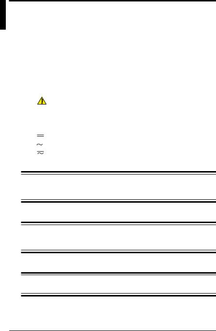
Diagram Block ■
Functions .1
Functions
1

1.Functions
■Main Functions
•Source
The calibrator sources a voltage, current, resistance, thermocouple (TC), RTD, frequency or pulse signal at a preset level.
Function |
Description |
DC voltage |
Sources a DC voltage signal in the 100 mV, 1 V, 10 V or 30 |
|
V range. |
DC current |
Sources a DC current signal in the 20 mA range. |
SINK current |
Draws a sink current from an external power source in the |
|
20 mA range. |
Resistance |
Sources a resistance signal in the 400 Ω range. |
Thermocouple (TC) |
Sources a thermoelectromotive force corresponding to the |
|
temperature detected by a type-K, E, J, T, R, B, S, N, L or U |
|
thermocouple.*1 |
RTD |
Sources resistance corresponding to the temperature de- |
|
tected by a Pt100 or JPt100 RTD.*2 |
Frequency and pulse |
Sources a continuous pulse train with frequency in the 500 |
|
Hz, 1 kHz or 10 kHz range. This function also sources the |
|
preset number of pulses defined by the frequency men- |
|
tioned above. |
|
|
1-2 |
IM CA71-E |

1. Functions
•Measurement
Independent of the source function, the calibrator measures DC voltage, AC voltage, DC current and resistance signals, a temperature signal based on a thermocouple (TC) or RTD, as well as frequency and the number of pulses.
Function |
Description |
DC voltage |
Measures a DC voltage signal in the 100 mV, 1 V, 10 V or |
|
100 V range. |
AC voltage |
Measures a DC voltage signal in the 1 V, 10 V, 100 V or 300 |
|
V range. |
DC current |
Measures a DC current signal in the 20 mA or 100 mA |
|
range. |
|
The current terminals are equipped with a built-in |
|
overrange input protection fuse. |
Resistance |
Measures a resistance signal in the 400 Ω range. |
Thermocouple (TC) |
Measures temperature according to the type of thermo- |
|
couple – K, E, J, T, R, B, S, N, L or U.*1 (CA71 only) |
RTD |
Measures temperature according to the type of RTD – |
|
Pt100 or JPt100. *2 (CA71 only) |
Frequency and pulse |
Measures frequency in the 100 Hz, 1 kHz or 10 kHz range. |
|
For pulse signals, this function measures the number of |
|
pulses as a CPM (count per minute) or CPH (count per |
|
hour) reading. |
|
|
You can also select and configure the following functions.
Function |
Description |
Divided output function(n/m) |
|
|
Sources a “setpoint× (n/m)” output signal, where the vari- |
|
ables m and n are defined as m = 1 to 19 and n = 0 to m. |
Memory |
Stores up to 50 sourced and measured values as a set. |
Sweep |
Changes the output signal in a linear manner. |
Auto step |
Automatically changes the value of n in a setpoint × n/m |
output in a step-by-step manner.
1
Functions
IM CA71-E |
1-3 |

1.Functions
•Power Supply
The calibrator operates on AA-size (LR6) alkaline batteries or the optional AC adapter.
*1: The thermocouples comply with the Japanese Industrial Standard JIS C1602-1995 (ITS-90), except for the type-L and U thermocouples that comply with DIN.
*2: The RTD comply with the Japanese Industrial Standard JIS C1604-1997
(ITS-90). The internal DIP switch can be configured so that the detectors comply with IPTS-68 instead.
1-4 |
IM CA71-E |

2. Names and Functions of Parts
5
3 4
11
6 |
12 |
7 |
13 |
1 |
8 |
9 10 |
19 |
18 |
17 2 |
16 15 |
14 |
20
21
22
23
24
2
and Names
of Functions
Parts
IM CA71-E |
2-1 |

2. Names and Functions of Parts
■ Front Panel
1POWER Key
Turns on/off the power supply.
2LIGHT Key
Turns on/off the backlight of the LCD.
MEASURE Mode – Functions for Measurement
3DC Voltage, AC Voltage, Resistance and Pulse Input Terminals Serve as H (positive) and L (negative) input terminals when you measure DC voltage, AC voltage, resistance, and pulse signals.
4DC Current Input Terminals
Serve as H (positive) and L (negative) input terminals when you measure a DC current signal. Also serve as L’ terminals when you carry out 3-wire resistance measurement.
5Three-wire Input Terminals
6Function Selector Switch
Selects a measurement function and its range.
7RANGE DC/AC Key
Used to further select from range options within the selected function.
•If you have selected the 1 V, 10 V or 100 V range, use this key to toggle between the DC and AC options.
•If you have selected the FREQ range, use this key to select the range of frequency measurement, as the key cycles through the 100 Hz, 1 kHz, 10 kHz, CPM and CPH options.
•If you have selected the mA range, use this key to select from the 20 mA and 100 mA ranges.
•If you have selected the 100 mV TC range, use this key to select the voltage range or the type of thermocouple, as the key cycles through the 100 mV, K, E, J, T, R, B, S, N, L and U options. (CA71 only)
•If you have selected the Ω RTD range, use this key to select the
resistance range or the type of RTD, as the key cycles through the 400 Ω , Pt100 and JPt100 options. (CA71 only)
If you have selected the TC or RTD range in the source mode of display, the TC or RTD type options on the SOURCE function side precede those on the MEASURE mode side.
2-2 |
IM CA71-E |

2. Names and Functions of Parts
8MEASURE OFF Key
Turns on/off the MEASURE mode. Turning off the mode causes the measured value shown on the LCD to disappear. If the MEASURE
mode is not in use and therefore turned off, the power to the measurement circuit within the calibrator is also turned off. This strategy saves on battery power if the calibrator is running on batteries.
9HOLD Key
Holds the measured value being displayed. Also used to start CPM or CPH measurement or communication.
10MEM Key
Used to turn on/off the memory function.
SOURCE Mode – Functions for Generation
11Output Terminals
These terminals are common to all of the source functions.
12Function Selector Switch
Selects a source function and its range.
13RANGE Key
Used to further select from range options within the selected function.
•If you have selected the 100 mV TC range, use this key to select the voltage output or the type of thermocouple, as the key cycles through the 100 mV, K, E, J, T, R, B, S, N, L and U options.
•If you have selected the 400 Ω RTD range, use this key to select the
resistance range or the type of RTD, as the key cycles through the 400 Ω , Pt100 and JPt100 options.
•If you have selected the PULSE range, use this key to select the frequency range, as the key cycles through the 500.0 Hz, 1000 Hz and 10 kHz options.
14SOURCE ON Key
Turns on/off the source output.
15PULSE SET Key
If you have selected the PULSE range, use this key to cycle through the frequency, amplitude and pulse count options for pulses being generated.
16TEMP Key
Allows you to monitor temperature by selecting from the room temperature (°C), reference junction temperature (°C), thermocouple (mV) and RTD (Ω ) options.
2
and Names
of Functions
Parts
IM CA71-E |
2-3 |

2. Names and Functions of Parts
17n/m Key
Turns on/off the divided output function (n/m).
18▲ and ▼ Output Setting Keys
Set the output value of a source function. Each pair of ▲ and ▼ keys corresponds to each digit of the reading, thus increasing/decreasing the digit in units of 1s. Increasing the digit from 9 or decreasing it from 0 causes the digit to overflow or underflow, allowing you to set the output value without interruption. Holding down the ▲ or ▼ key continuously changes the digit in question.
If your choice is the 4–20 mA function, see Section 4.2, “Sourcing DC Voltage, DC Current or SINK Current Signal,” for further details. Note that ▲ and ▼ keys are also used in the following ways:
•The ▲ and ▼ keys labeled n and m serve as keys for setting the variables n and m when you have selected the divided output function (n/m). (See Section 4.6, “Divided Output Functionn/m( ),” for further details.)
•The ▲ and ▼ keys labeled MEM NO., SAVE and READ serve as keys for working with the memory when you have selected the memory function. (See Chapter 6, “Memory Function,” for further details.)
19CLEAR Key
Initializes the output setpoint, causing the on-screen reading to revert to 0000 for functions other than PULSE and 20 mA SINK, though the number of digits depends on function selected. This key serves as a key for clearing the memory when the memory function is selected.
■ Side and Rear Panels
20FUSE
A holder for housing a fuse that protects the input during DC current measurement.
21R.J.INPUT
A connector to which the external reference junction compensation sensor is connected.
22AC Adapter Connection Jack
23Battery Holder
Opening the cover reveals the battery holder and DIP switch.
2-4 |
IM CA71-E |
2. Names and Functions of Parts
24I/O Port Cover
Open this cover to connect the RS232 communication cable (P/N: 91017). (CA71 only)
a |
c |
|
|
|
|
|
|
|
|
|
d |
|
|
l |
|
|
|
|
|
b |
e |
|
|
|
f |
|
|
|
|
|
|
|
|
|
|
|
|
|
k |
|
g |
h |
i |
j |
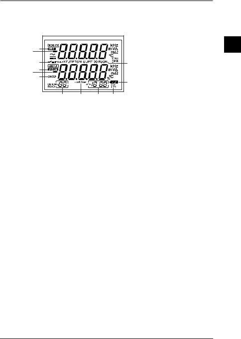
■ LCD Unit
a.Measured value
b.Setpoint for source
c.HOLD indicator
Indicates the on-screen measured value is in a hold state.
d.Contact input
Indicates the contact input is selected when your choice is pulse measurement.
e.ON/OFF indicators for output ON: Indicates the output is on. OFF: Indicates the output is off.
f.SWEEP indicator for sweep function
Comes on when the sweep function is selected using the DIP switch.
g.MEM NO. indicator
Shows a memory number when the memory function is selected.
h.AUTO STEP indicator
Comes on when the auto step function is selected.
i.Divided output function (n/m) indicator
Comes on when the divided output function (n/m) is selected. The most significant two digits “18” denote the value ofn, while the least significant two digits “88” mean the value ofm.
j.CAL mode selection indicator
The 0 and FS indicators below this indicator denote zero point and full scale adjustments, respectively.
2
and Names
of Functions
Parts
IM CA71-E |
2-5 |

2.Names and Functions of Parts
k.Battery replacement indicator
Shows the battery level in three steps according to the level of remaining electricity.
l.RJON indicator
Indicates reference junction compensation is active when
thermoelectromotive force is being sourced. The thermoelectromotive force output when this indicator is off represents the 0°C-based output.
2-6 |
IM CA71-E |
3. Before Starting Source/Measurement
■ Operating Precautions
Precautions for Safe Use of the Instrument
●When using the instrument for the first time, be sure to read the instructions given on pages iv and v of the section, “Precautions for Safe Use
of the Instrument.”
●Do not open the instrument’s case.
Opening the case is extremely hazardous, as the instrument contains high-voltage parts. Contact the vendor from which you purchased the instrument, for a service of inspecting or adjusting the internal assembly.
●In case of failure
Should the instrument begin to emit smoke, give off an unusual odor, or show any other anomaly, immediately turn off the POWER key. If you are using an AC adapter, disconnect the plug from the wall outlet. Also cut off power to the object under test that is connected to the input terminals. Then, contact the vendor from which you purchased the instrument.
●AC adapter
Use an AC adapter dedicated to the instrument. Avoid placing any load on the AC adapter, or prevent any heat-emitting object from coming into contact with the adapter.
General Handling Precautions
●Before carrying around the instrument turn off power to the object under test, and then the POWER key of the instrument. If you are using an AC adapter, disconnect the power cord from the wall outlet. Finally, detach all lead cables from the instrument. Use a dedicated carry case when transporting the instrument.
●Do not bring any electrified object close to the input terminals, since the internal circuit may be destroyed.
●Do not apply any volatile chemical to the instrument’s case or operation panel. Do not leave the instrument in contact with any product made of rubber or vinyl for a prolonged period. Be careful not to let a soldering iron or any other heat-emitting object come into contact with the operation panel, as the panel is made of thermoplastic resin.
3
Starting Before
Source/Measurement
IM CA71-E |
3-1 |

3.Before Starting Source/Measurement
●Before cleaning the instrument’s case or operation panel disconnect the power cord plug from the wall outlet if you are using an AC adapter. Use a soft, clean cloth soaked in water and tightly squeezed to gently wipe the outer surfaces of the instrument. Ingress of water into the instrument can result in malfunction.
●If you are using an AC adapter with the instrument and will not use the instrument for a prolonged period, disconnect the power cord plug from the wall outlet.
●For handling precautions regarding the batteries, see “Installing or Replacing the Batteries” on page 3-3.
●Never use the instrument with the cover of the battery holder opened.
■Environmental Requirements
Use the instrument in locations that meet the following environmental requirements:
• Ambient temperature and humidity
Ambient temperature range: |
0 to 50°C |
Ambient humidity range: |
20 to 80% RH. Use the instrument |
|
under non-condensing condition. |
• Flat and level locations |
|
Do not use the instrument in locations that are:
•exposed to direct sunlight or close to any heat source;
•exposed to frequent mechanical vibration;
•close to any noise source, such as high-voltage equipment or motive power sources;
•close to any source of intensive electric or electromagnetic fields;
•exposed to large amounts of greasy fumes, hot steam, dust or corrosive gases;
•unstable; or
•exposed to a risk of explosion due to the presence of flammable gases.
3-2 |
IM CA71-E |

3. Before Starting Source/Measurement
 NOTE
NOTE
•Use the instrument under the following environmental conditions if precise source or measurement is your requirement:
Ambient temperature range: 23±5°C; ambient humidity range: 20 to 80% RH
(non-condensing)
When using the instrument within a temperature range of 0 to 18°C or 28 to 50°C, add a value based on the temperature coefficient shown in Chapter 12,
“Specifications (page 12-1),” to the given accuracy rating.
•When using the instrument at an ambient humidity of 30% or lower, prevent electrostatic charges from being produced, by using an antistatic mat or any other alternative means.
•Condensation may occur if you relocate the instrument from places with low temperature and humidity to places with high temperature and humidity, or if the instrument experiences any sudden temperature change. In that case, leave the instrument under the given ambient temperature for at least one hour to ensure that the instrument is free from condensation, before using the instrument.
■ Installing or Replacing the Batteries
 WARNING
●To avoid electrical shock, always remove the source or measurement lead cables from the object under test, as well as from the instrument itself.
 CAUTION
•To avoid the risk of fluid leakage or battery explosion, install batteries with their positive and negative electrodes correctly positioned.
•Do not short-circuit the batteries.
•Do not disassemble or heat the batteries or throw them into fire.
•When replacing batteries, replace all of the four batteries at the same time with new ones from the same manufacturer.
•If the instrument will not be used for a prolonged period, remove the batteries from the instrument.
3
Starting Before
Source/Measurement
IM CA71-E |
3-3 |
3. Before Starting Source/Measurement
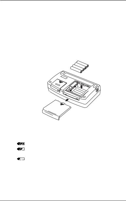
Step 1: Remove the lead cables and AC adapter and turn off the calibrator before you begin installing batteries.
Step 2: Remove the battery holder cover by sliding it in the direction indicated by → OPEN.
Step 3: Install four AA-size (LR6) alkaline batteries in the battery holder with their positive and negative electrodes positioned correctly as indicated on the holder.
Step 4: After replacement, reattach the battery holder cover.
OPEN
OPEN
Indication of Battery Level
The battery replacement indicator shows the battery level in three steps according to the measured voltage of the batteries.
(lit constantly) ...... |
The battery level is normal. |
(lit constantly) ...... |
The battery level is below 50% full, but still |
|
allows for normal operation. |
(flashing) ............. |
Replace the batteries. |
Note that the battery replacement indicator is driven by directly measuring the battery voltage when the calibrator is in actual operation. Consequently, the indicator may read differently depending on the battery load condition (e.g., the load condition of the source output or on/ off state of the measurement function) if the batteries are too low.
3-4 |
IM CA71-E |
3. Before Starting Source/Measurement
If the calibrator will be used under a wide variety of conditions, it is advisable that the battery replacement indicator be verified under heavy loads (MEASURE mode is on and the SOURCE mode is set to the 20 mA/10 V output).
■ Connecting the AC Adapter
 WARNING
●Make sure the voltage of the AC power source matches the rated supply voltage of the AC adapter, before connecting the AC adapter to the AC power source.
●Do not use any AC adapter other than the dedicated AC adapter from Yokogawa M&C Corporation.
Step 1: Make sure the calibrator is turned off.
Step 2: Insert the plug of the optional AC adapter into the AC adapter connection jack.
■ Turning On/Off the Power
Turning On/Off the POWER Switch
•Pressing the key once when the power is off turns on the calibrator. Pressing the
 key once again turns off the calibrator.
 NOTE
NOTE
Before disconnecting the AC adapter from an AC power source, turn off the calibrator by pressing the  key.
key.
 NOTE
NOTE
When operating the calibrator on batteries, disconnect the AC adapter plug from the instrument. Once you connect the AC adapter plug to the instrument, the instrument no longer operates on batteries. Thus, the instrument will not turn on unless the AC adapter is connected to an AC power source.
3
Starting Before
Source/Measurement
IM CA71-E |
3-5 |

3. Before Starting Source/Measurement
Turning On/Off MEASURE Mode
Pressing the 


 key after power-on turns off the MEASURE mode.
•If the MEASURE mode is not needed and therefore turned off, power to the measurement circuit is also turned off within the calibrator. Thus, you can save on battery power if the calibrator is running on batteries.
•Turning off the MEASURE mode causes the on-screen measured value to disappear.
•To resume measurement when the MEASURE mode is off, press the 


 key once again.
TIP
One to two seconds are taken for the LCD to turn on after the MEASURE mode is
turned on.
■Automatic Power-off
•When the calibrator is running on batteries and no key is operated for approximately nine minutes, all elements on the LCD begin to blink. The calibrator gives off a buzzer sound to alert you. If you still do not operate any key for another 30 seconds, the calibrator automatically turns off. The automatic power-off feature is factory-set to ON.
•To continue using the calibrator after the LCD has begun blinking,
press any key other than the  key. The LCD stops blinking and lights steady, allowing you to continue from the original status of the
calibrator.
•The automatic power-off feature is disabled if the calibrator is operated on the AC adapter.
•To disable the automatic power-off feature when the calibrator is bat- tery-operated, see Section 7.8, “Disabling the Automatic Power-off Feature.”
3-6 |
IM CA71-E |

3.Before Starting Source/Measurement
■Turning On/Off the Backlight
The LCD can be back-lit. Pressing the  key turns on the backlight, while pressing the key once again turns it off. This feature makes it easier for you to view the LCD when operating the calibrator in dark places or when carrying out source or measurement. Note that battery life shortens when the calibrator is operated on batteries.
 NOTE
NOTE
The backlight automatically turns off approximately one minute later. To turn on the backlight again, press the  key once again.
3
Starting Before
Source/Measurement
IM CA71-E |
3-7 |

3. Before Starting Source/Measurement
■ Operating Environment
Operating Environment
Ambient Temperature and Humidity
Use the CA51/71 in the following environment:
•Ambient temperature: 0 to 50°C
•Ambient humidity: 20 to 80 % RH (no condensation)
Operating Altitude
2000 m max. above sea level.
Location
Indoors
Measurement Category (CAT.)
The measurement category of the CA51/71 is III (300 Vrms max.).
 WARNING
Do not use the CA150 for measurements in locations falling under Measurement Categories IV.
3-8 |
IM CA71-E |
3. Before Starting Source/Measurement
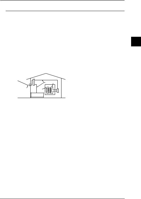
Measurement Category
Measurement Category |
Description |
Remarks |
|
I |
CAT. I |
For measurement performed |
|
|
|
on circuits not directly |
|
|
|
connected to MAINS. |
|
|
|
|
|
II |
CAT. II |
For measurement performed |
Appliances, portable |
|
|
on circuits directly connected |
equipments, etc. |
|
|
to the low voltage installation. |
|
|
|
|
|
III |
CAT. III |
For measurement performed |
Distribution board, |
|
|
in the building installation. |
circuit breaker, etc. |
|
|
|
|
IV |
CAT. IV |
For measurement performed |
Overhead wire, |
|
|
at the source of low-voltage |
cable systems, etc. |
|
|
installation. |
|
|
|
|
|
|
Internal Wiring |
|
|
Distribution |
CAT.III CAT.II |
|
Board |
|
Entrance |
|
|
|
|
|
Cable |
|
T |
CAT.IV |
CAT.I |
|
|
|
|
|
Fixed Equipment, |
Outlet |
|
etc. |
Equipment |
|
|
|
Pollution Degree
Pollution Degree applies to the degree of adhesion of a solid, liquid, or gas which deteriorates withstand voltage or surface resistivity.
The pollution degree of the CA150 in the operating environment is 2. Pollution Degree 2 applies to normal indoor atmospheres. Normally, only non-conductive pollution is emitted. However, a temporary electrical conduction may occur depending on the concentration.
3
Starting Before
Source/Measurement
IM CA71-E |
3-9 |

4. Source
From the calibrator, you can source a DC voltage, DC current, SINK current, resistance, thermocouple, RTD, frequency or pulse signal.
 WARNING
●To avoid electrical shock, do not apply any voltage above 30 V to the output terminals. Always use the calibrator in locations with a voltage to ground below 30 V.
 CAUTION
•Do not apply any voltage to the output terminals for ranges other than 20 mA SINK. Otherwise, the internal circuitry may be damaged.
•The instrument has been calibrated without taking into account a voltage drop due to the resistance component of the lead cables for source. Care
must be taken therefore when drawing a load current since the voltage drop due to the resistance component (approximately 0.1 Ω on a round-trip basis) of the lead cables serves as an error.
4
Source
IM CA71-E |
4-1 |
 Loading...