


 Loading...
|
|
Instruction |
DR232/DR242 |
Manual |
Hybrid Recorder |
|
(Expandable Type) |
IM DR232-01E
IM DR232-01E
9th Edition

Foreword
Thank you for purchasing the YOKOGAWA Hybrid Recorder DR232 or DR242.
This User’s Manual contains useful information regarding the instrument’s functions and operating procedures, as well as precautions that should be observed during use. To ensure proper use of the instrument, please read this manual thoroughly before operating the instrument.
Keep the manual in a safe place for quick reference whenever a question arises. The following manual is provided with the instrument in addition to this manual.
Manual Name |
Manual No. |
DR231/DR232/DR241/DR242 Communication Interface |
IMDR231-11E |
|
|
Notes
•DARWIN is a system comprising a number of data-acquisition equipment components. In the course of system growth, new models, software, various input/output modules and optional features are added to the family to enhance the systems expandability and flexibility. You can check the versions of your equipment and software by referring to the style number (Sn) and release number (Rn) respectively which are shown on the nameplate of the main unit.
When configuring a system, you must confirm that the style number of each component unit and software meets the following requirements:
1 the style number of each input/output module must be the same as or lower than that of the main unit or subunit to which the module is connected.
2the release number of a dedicated software package must be the same or higher than the style number of the main unit or subunit where the package is installed and where it performs control.
Any equipment/software not meeting these requirements might have incompatible areas with your system configuration.
In this manual, equipment of style S8 is explained.
For unsupported functions as classified by the style number, see the next page.
•The contents of this manual are subject to change without prior notice as a result of improvements in the instrument’s performance and functions.
•Every effort has been made in the preparation of this manual to ensure the accuracy of its contents. However, should you have any questions or find any errors, please contact your nearest YOKOGAWA representative as listed on the back cover of this manual.
•Copying or reproduction of all or any part of the contents of this manual without YOKOGAWA’s permission is strictly prohibited.
Trademarks
DOS and Windows are registered trademarks of Microsoft Corporation.
IBM is a registered trademark of International Business Machines Corporation.
Revisions
1st Edition: January 1996 2nd Edition: February 1996 3rd Edition: June 1996
4th Edition: November 1996 5th Edition: March 1997 6th Edition: November 1997 7th Edition: November 1998 8th Edition: June 2000
9th Edition: October 2000
Disk No. RE04
9th Edition: October 2000 (YK)
All Rights Reserved, Copyright 1996 Yokogawa Electric Corporation
IM DR232-01E |
1 |
|

Unsupported Functions As Classified by the Style Number
The following functions are not available for style number S1
•Computation function (including remote RJC)
•Saving and reading of measured data, computated data and set-up data (FDD function)
•Summer/Winter time
•RS-422-A/RS-485 cs£munication module
•Pulse input module
•mA, Strain and AC input module
•Extender module and Extender base
•Report function
•Ethernet module
•Digital input module
•Flag and group reset functions (for /M1 option)
•The measuring of active power and apparent power on CH3 to CH6 for power monitor module. The following functions are not available for style number S2
•Summer/Winter time
•RS-422-A/RS-485 communication module
•Pulse input nodule
•mA, Strain and AC input module
•Extender module and Extender base
•Report function
•Ethernet module
•Digital input module
•Flag and group reset functions (for /M1 option)
•The measuring of active power and apparent power on CH3 to CH6 for power monitor module. The following functions are not available for style number S3
•Pulse input module
•mA, Strain and AC input module
•Extender module and Extender base
•Report function
•Ethernet module
•Digital input module
•Flag and group reset functions (for /M1 option)
•The measuring of active power and apparent power on CH3 to CH6 for power monitor module. The following functions are not available for style number S4 and S5
•mA, Strain and AC input module
•Extender module and Extender base
•Report function
•Ethernet module
•Digital input module
•Flag and group reset functions (for /M1 option)
•The measuring of active power and apparent power on CH3 to CH6 for power monitor module. Products with style number S6 is not sold.
The following functions are not available for style number S7
•Ethernet module
•Digital input module
•Flag and group reset functions (for /M1 option)
•The measuring of active power and apparent power on CH3 to CH6 for power monitor module.
2 |
IM DR232-01E |
|


 Checking the Contents of the Package
Unpack the box and check the contents before operating the instrument. In case the wrong instrument or accessories have been delivered, or if some accessories are not present, or if they seem abnormal, contact the dealer from which you purchased them. Furthermore, please contact a Yokogawa representative to order any of parts as follows.
Main Unit DR232/DR242
Check that the model and suffix code given on the name plate are according to your order.
Model and Suffix Codes
Model |
Suffix Code |
Description |
|
DR232 |
....................... |
|
Hybrid recorder, desktop type |
DR242 |
....................... |
|
Hybrid recorder, panel-mount type |
|
|
|
|
Memory |
-0 |
.................... |
No memory |
|
-1 |
.................... |
3.5inch Floppy disk drive |
|
|
|
|
Software |
|
0 ................. |
Without data acquisition software |
|
|
2 ................. |
With data acquisition software |
|
|
|
|
Input Type |
|
-00 ............ |
Always “-00” |
|
|
|
|
Power Supply |
-1 ......... |
100-240VAC |
|
|
|
|
|
Power Cord |
|
D ......... |
3-pin inlet w/UL, CSA cable* (Part No. A1006WD) |
|
|
F ......... |
3-pin inlet w/VDE cable* (Part No. A1009WD) |
|
|
R ......... |
3-pin inlet w/SAA cable* (Part No. A1024WD) |
|
|
S ......... |
3-pin inlet w/BS cable* (Part No. A1023WD) |
|
|
W ........ |
3-pin inlet with screw conversion terminal** |
|
|
* For DR232 only |
|
|
|
**For DR242 only |
|
|
|
|
|
Options |
|
/M1 . Mathematical Func. |
|
|
|
/M3 . Report Func. |
|
|
|
/H1 .. |
Internal illumination |
|
|
/D2 .. |
deg F Display |
|
|
|
|
NO. (Instrument Number), Style number (equipment) and Release number (software package)
Please refer to these numbers when contacting the dealer.
Subunit DS400/DS600
Check that the model and suffix code given on the name plate are according to your order.
Model and Suffix Codes
Model |
Suffix Code |
Description |
DS400 |
....................... |
4-module connection subunit |
DS600 |
....................... |
6-module connection subunit |
|
|
|
Type |
00 ................... |
always 00 |
|
|
|
Power Supply -1 ............. |
100-240VAC |
|
|
-2 ............. |
12-28V DC |
|
|
|
Power Cord |
D ......... |
3-pin inlet w/UL, CSA cable (Part No. A1006WD) |
|
F ......... |
3-pin inlet w/VDE cable (Part No. A1009WD) |
|
R ......... |
3-pin inlet w/SAA cable (Part No. A1024WD) |
|
S ......... |
3-pin inlet w/BS cable (Part No. A1023WD) |
|
W ........ |
3-pin inlet with screw conversion terminal (when power supply suffix code is |
|
|
-1) |
|
Y ......... |
2-pin inlet with round-type connector (when power supply suffix code is -2) |
|
|
|
NO. (Instrument Number) and Style number (equipment)
Please quote these numbers when contacting the dealer.
IM DR232-01E |
3 |
|

Checking the Contents of the Package
Input Modules
Check that the model code given on the name plate is according to your order.
Model Codes
Model |
Description |
DU100-11 |
10-channel universal input module, screw type terminal |
DU100-21 |
20-channel universal input module, screw type terminal |
DU100-31 |
30-channel universal input module, screw type terminal |
|
|
DU100-12 |
10-channel universal input module, clamp type terminal |
DU100-22 |
20-channel universal input module, clamp type terminal |
DU100-32 |
30-channel universal input module, clamp type terminal |
|
|
DU200-11 |
10-channel DCV/TC/DI input module, screw type terminal |
DU200-21 |
20-channel DCV/TC/DI input module, screw type terminal |
DU200-31 |
30-channel DCV/TC/DI input module, screw type terminal |
|
|
DU200-12 |
10-channel DCV/TC/DI input module, clamp type terminal |
DU200-22 |
20-channel DCV/TC/DI input module, clamp type terminal |
DU200-32 |
30-channel DCV/TC/DI input module, clamp type terminal |
|
|
DU300-11 |
10-channel, mA-input module with screw terminals |
|
|
DU300-12 |
10-channel, mA-input module with clamp terminals |
|
|
DU400-12 |
Power monitor module for single-phase use |
DU400-22 |
Power monitor module for three-phase use |
|
|
DU500-12 |
10-channel, strain input module with 120-Ω bridge resistors |
DU500-22 |
10-channel, strain input module with 350-Ω bridge resistors |
DU500-32 |
10-channel, strain input module with NDIS terminals |
|
|
DU600-11 |
10-channel, pulse input module with screw terminals |
|
|
DU700-11 |
10-channel, digital input module with screw terminal |
|
|
NO. (Instrument Number)
Please quote this instrument number when contacting the dealer.
I/O Terminal Modules
Check that model code given on the name plate is according to your order.
Model Codes
Model |
Description |
DT100-11 |
DI/DO module, screw type terminal |
|
|
DT200-11 |
Alarm module (4 transfer contacts), screw type terminal |
DT200-21 |
Alarm module (10 make contacts), screw type terminal |
|
|
DT300-11 |
GP-IB module |
DT300-21 |
RS-232-C module, D-sub terminal |
DT300-31 |
RS-422-A/RS-485 module |
DT300-41 |
Ethernet module |
|
|
NO. (Instrument Number) and Style number (equipment)
Please quote these numbers when contacting the dealer.
4 |
IM DR232-01E |
|
|
|
|
|
|
Checking the Contents of the Package |
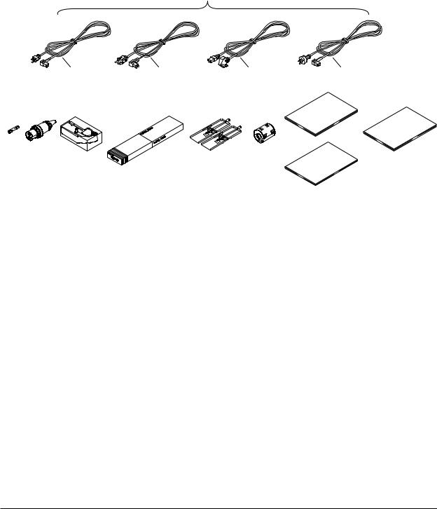
Standard Accessories |
|
|
|
|
|
|
|
|
|
|
|
|
Name |
Part No. |
Q’ty |
Description |
|
|
|
|
|
|
|
1. |
Power cord |
see page 2, 3 |
1 |
|
|
2. |
Fuse |
A1350EF |
1 |
Timelag 2.5A 250V, for DR232/242, in case of |
|
|
|
|
|
|
DR232 located in fuse holder |
3. |
DC power supply |
A1105JC |
1 |
Only for the subunit models whose power supply |
|
|
|
terminal connector |
|
|
code is “-2” |
4. |
Ribbon cassette |
B9627AZ |
1 |
10 colors (for DR232/242) |
|
5. |
Chart paper |
B9627AY |
1 |
Length: 30m, 25mm grid (for DR232/DR242) |
|
6. |
Mounting brackets |
B9900CW |
1 x 2 |
for DR242 |
|
7. |
Clamp filter |
A1197MN |
1 |
When power supply code is -1 |
|
8. |
User’s Manual |
IMDR232-01E |
1 |
this manual (for DR232/242) |
|
9. |
User’s Manual |
IMDR231-11E |
1 |
Communication Interface manual (for DR232/242) |
|
|
10. Data acquisition software |
DP120-13 |
|
Only for models whose software code is “-2” |
|
|
|
|
|
|
|
1.One of these power cord types is supplied according to the instrument's suffix code
|
|
D |
|
F |
S |
R |
|
|
|
|
|
|
8. |
2. |
3. |
4. |
5. |
6. |
7. |
10. |
|
|
|
|
|
|
9. |
IM DR232-01E |
5 |
|

Name |
Model |
Description |
Extender module |
DV100-011 |
|
Extender base |
DV100-012 |
|
Extension cable |
DV200-000 |
Length: 0.5m |
Extension cable |
DV200-001 |
Length: 1m |
Extension cable |
DV200-002 |
Length: 2m |
Extension cable |
DV200-005 |
Length: 5m |
Extension cable |
DV200-010 |
Length: 10m |
Extension cable |
DV200-020 |
Length: 20m |
Extension cable |
DV200-050 |
Length: 50m |
Extension cable |
DV200-100 |
Length: 100m |
Extension cable |
DV200-200 |
Length: 200m |
Extension cable |
DV200-300 |
Length: 300m |
Extension cable |
DV200-400 |
Length: 400m |
Extension cable |
DV200-500 |
Length: 500m |
|
|
|
Shunt resistance |
DV300-011 |
10Ω, for screw |
Shunt resistance |
DV300-012 |
10Ω, for clamp |
Shunt resistance |
DV300-101 |
100Ω, for screw |
Shunt resistance |
DV300-102 |
100Ω, for clamp |
Shunt resistance |
DV300-251 |
250Ω, for screw |
Shunt resistance |
DV300-252 |
250Ω, for clamp |
Rack mount kit |
DV400-011 |
for DS400/600 |
Rack mount kit |
DV400-013 |
for DR232 |
|
|
|
Power cable |
DV400-051 |
between DR232/242 and DS400/600 |
|
|
|
Strain conversion cable |
DV450-001 |
|
|
|
|
Cable adapter |
DV250-001 |
For expanding cable |
|
|
|
AC adapter |
DV500-001 |
2-pin inlet w/UL, CSA cable (Part No. B9988YA) for |
|
|
DC100/DA100/DS400/DS600 DC power supply model |
|
|
|
AC adapter |
DV500-002 |
2-pin inlet w/VDE cable (Part No. B9988YB) for |
|
|
DC100/DA100/DS400/DS600 DC power supply model |
|
|
|
AC adapter |
DV500-003 |
2-pin inlet w/SAA cable (Part No. B9988YC) for |
|
|
DC100/DA100/DS400/DS600 DC power supply model |
|
|
|
AC adapter |
DV500-004 |
2-pin inlet w/BS cable (Part No. B9988YD) for |
|
|
DC100/DA100/DS400/DS600 DC power supply model |
|
|
|
Optional Software
Name |
Model |
Description |
|
DAQ 32 |
DP120-13 |
Windows 95/98 and Windows NT |
|
DAQ 32 Plus |
DP320-13 |
Windows 95/98 and Windows NT |
|
Name |
Part No. |
Min. Q’ty |
Description |
Ribbon cassette |
B9627AZ |
1 |
10 colors |
Chart paper |
B9627RY |
10 |
Length 30 m, grid 10mm |
Checking the Contents of the Package |
B9627AY |
10 |
Length 30 m, grid 25mm |
Optional Accessories |
|
|
|
Spares
6 |
IM DR232-01E |
|

 Safety Precautions
This instrument is an IEC safety class I instrument (provided with terminal for protective grounding).
The following general safety precautions must be observed during all phases of operation, service and repair of this instrument. If this instrument is used in a manner not sepecified in this manual, the protection provided by this instrument may be impaired. Also, YOKOGAWA Electric Corporation assumes no liability for the customer’s failure to comply with these requirements.
The following symbols are used on this instrument.
To avoid injury, death of personnel |
Alternating current. |
or damage to the instrument, the |
|
operator must refer to an explanation |
ON(power). |
in the User’s Manual or Service |
|
|
|
Manual. |
OFF(power). |
Protective grounding terminal. |
|
Function grounding terminal. This terminal should not be used as a “Protective grounding terminal”.
Make sure to comply with the following safety precautions. Not complying might result in injury, death of personnel or damage to the instrument.
WARNING
Power Supply
Ensure the source voltage matches the voltage of the power supply before turning ON the power.
Power Cord and Plug
To prevent an electric shock or fire, be sure to use the power cord supplied by YOKOGAWA. The main power plug must be plugged in an outlet with protective grounding terminal. Do not invalidate protection by using an extension cord without protective grounding.
Protective Grounding
Make sure to connect the protective grounding to prevent an electric shock before turning ON the power.
Necessity of Protective Grounding
Never cut off the internal or external protective grounding wire or disconnect the wiring of protective grounding terminal. Doing so poses a potential shock hazard.
Defect of Protective Grounding and Fuse
Do not operate the instrument when protective grounding or fuse might be defective.
Do not Operate in an Explosive Atmosphere
Do not operate the instrument in the presence of flammable liquids or vapors. Operation of any electrical instrument in such an environment constitutes a safety hazard.
Fuse
To prevent a fire, make sure to use fuses with specified standard(current, voltage, type). Before replacing the fuse, turn OFF the power and disconnect the power source. Do not use a different fuse or short-circuit the fuse holder.
Do not Remove any Covers
There are some areas with high voltages. Do not remove any cover if the power supply is connected. The cover should be removed by qualified personnel only.
External Connection
To ground securely, connect the protective grounding before connecting to measurement or control unit.
IM DR232-01E |
7 |
|


 How to Use this Manual
This User’s Manual consists of the following twelve chapters and Index.
Chapter |
Title |
Description |
Chapter 1 |
System Configuration |
Explains the position of the DR within DARWIN, its |
|
|
configuration, etc.. |
Chapter 2 |
Functions |
Explains the functions of the DR. Operating |
|
|
procedures are not explained here. |
Chapter 3 |
Installation and Wiring |
Describes cautions for use, explains how to install and |
|
|
wire the DR, the power cord, how to switch ON/OFF |
|
|
the DR, how to set the date/time, explains the noise |
|
|
filter, etc.. |
Chapter 4 |
Setting the Monitor Mode |
Explains the display in the monitor mode. |
|
Display |
|
Chapter 5 |
Setting the Input Type/ |
Explains the operations when setting the input type, |
|
Recording Span/ |
recording span and linear scaling function. |
|
Linear Scaling |
|
Chapter 6 |
Setting the Recording |
Explains the operations when setting recording |
|
Conditions |
conditions such as the recording mode, channels, |
|
|
recording interval, chart speed, recording span, and |
|
|
recording format. |
Chapter 7 |
Executing Recording |
Explains how to start and stop recording. |
Chapter 8 |
Setting, Displaying and |
Explains how to set an alarm and what to do when an |
|
Recording Alarms |
alarm occurs. |
Chapter 9 |
Event/Action Function and |
Explains how to operate the event/action function,. |
|
Other Functions |
how to copy recording information, how to reset |
|
|
alarms, how to reset the timer, how to use the key- |
|
|
lock, and how to use the external in-/output function. |
Chapter 10 |
Basic Settings (SET UP) |
Explains functions which usually do not need to be |
|
|
changed, and how to set |
|
|
|
Chapter 11 |
Saving/Reading Measured, |
Explains how to save measured data, computed data |
|
Computed and Set-up Data |
and set-up data to the internal RAM disk or floppy |
|
|
disk and read them into the instrument. |
|
|
|
Chapter 12 |
Executing Computation |
Explains the computation function (optional). |
|
(Available with the /M1 Model) |
|
Chapter 13 |
Trouble-Shooting and |
Explains maintenance procedures, error messages and |
|
Maintenance |
calibration procedures. |
Chapter 14 |
Specifications |
Explains specifications for all features of DR. |
Index |
|
Gives the index in main menu and alphabetic order. |
8 |
IM DR232-01E |
|

 Conventions Used in this Manual
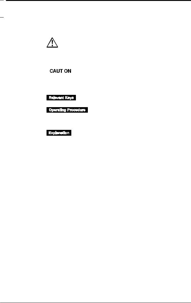
Used Symbols
The following symbol marks are used to attract the operator’s attention.
|
|
|
Affixed to the DR232/242, indicating that for safety, the operator should |
|
|
|
refer to the appropriate User’s Manual. For a list of the User’s Manuals, |
|
|
|
refer to page 1. |
|
|
|
Describes precautions that should be observed to prevent the danger of |
|
|
|
|
|
|
|
|
|
|
|
injury or death to the user. |
|
|
|
|
|
|
|
Describes precautions that should be observed to prevent damage to the |
|
|
|
|
|
|
|
|
|
|
|
DR232/242. |
|
|
|
|
Note |
Provides information that is important for proper operation of the DR232/ |
||
|
|
|
242. |
Indicates the relevant panel keys and indicators to carry out the operation.
The procedure is explained by a flow diagram. For the meaning of each operation, refer to the example below. The operating procedures are given with the assumption that you are not familiar with the operation. Thus, it may not be necessary to carry out all the steps when changing settings.
Describes settings and restrictions relating to the operation.
IM DR232-01E |
9 |
|

 Contents
Foreword |
.................................................................................................................................................................................. |
|
1 |
Checking the Contents of the Package ..................................................................................................................... |
3 |
||
Safety Precautions .............................................................................................................................................................. |
7 |
||
How to Use ....................................................................................................................................................this Manual |
8 |
||
Conventions ................................................................................................................................Used in this Manual |
9 |
||
List of Menus ....................................................................................................................................and Set-up Data |
13 |
||
Chapter 1 |
System Configuration |
|
|
................................................................................................................................... |
1.1 |
About DARWIN |
1-1 |
................................................................................................................................. |
1.2 |
Product Overview |
1-2 |
...................................................................................................................................... |
1.3 |
Names of Parts |
1-4 |
........................................................................................................................................ |
1.4 |
Floppy Disk |
1-11 |
Chapter 2 |
Functions |
|
|
................................................................................................................................. |
2.1 |
Display Functions |
2-1 |
.............................................................................................................. |
2.2 |
Measurement Input Functions |
2-3 |
............................................................................................................................. |
2.3 |
Recording Functions |
2-5 |
................................................................................................................................... |
2.4 |
Alarm Function |
2-13 |
....................................................................................................... |
2.5 |
Standard Computation Functions |
2-16 |
.................................................................................................................................. |
2.6 |
Other Functions |
2-17 |
Chapter 3 Installation and Wiring |
|
||
..................................................................................................... |
3.1 |
General Precautions for Installation |
3-1 |
....................................................................................................................................... |
3.2 |
How to Install |
3-2 |
......................................................................................... |
3.3 |
How to Connect the Input/Output Modules |
3-7 |
............................................................................................. |
3.4 |
Installing the Chart and Ribbon Cassette |
3-9 |
......................................................................................................... |
3.5 |
Connecting the Interface Cables |
3-14 |
...................................................................................................... |
3.6 |
Connecting the Extension Cables- |
3-19 |
............................................................................................................... |
3.7 |
Connecting the Signal Lines |
3-20 |
....................................................................... |
3.8 |
Connecting an Extension Module to Extension Bases |
3-28 |
........................................................... |
3.9 |
Connecting the Power Cord and Turning the Power ON/OFF |
3-30 |
.................................................................................................................. |
3.10 |
Setting the Date and Time |
3-35 |
................................................................................................................................ |
3.11 |
Countering Noise |
3-36 |
Chapter 4 Setting the Monitor Mode Display |
|
||
...................................................................................................................... |
4.1 |
Using the AUTO Display |
4-1 |
............................................................................................................... |
4.2 |
Using the MANUAL Display |
4-4 |
...................................................................................................................... |
4.3 |
Using the PAGE Display |
4-6 |
................................................................................................. |
4.4 |
Using the ALARM SEARCH Display |
4-7 |
........................................................................................................... |
4.5 |
Using the BARGRAPH Display |
4-9 |
................................................................................................. |
4.6 |
Using the ALARM STATUS Display |
4-10 |
.................................................................................................. |
4.7 |
Using the RELAY STATUS Display |
4-11 |
........................................................................................ |
4.8 |
Using the CLOCK (Data & Time) Display |
4-13 |
Chapter 5 Setting the Input Type/Recording/Span/Linear Scalling |
|
||
..................................................................................... |
5.1 |
Setting the Type of Input and Recording Span |
5-1 |
................................................................................... |
5.2 |
Setting Linear Scaling and the Recording Span |
5-4 |
5.3Configuring the Input Range and Recording Span or the Linear Scaling of a Power Monitoring
Channel ................................................................................................................................................. |
5-6 |
5.4Configuring the Measuring Range and Recording Span or the Linear Scaling of a Strain Input
Channel ............................................................................................................................................... |
5-10 |
10 |
IM DR232-01E |
|

|
|
Contents |
5.5 |
Performing Initial Balancing/Initialization on a Strain Input Channel |
............................................... 5-12 |
5.6 |
Configuring the Pulse Input Channel ................................................................................................. |
5-13 |
Chapter 6 Setting the Recording Conditions
6.1 |
Setting the Recording Mode, Engineering Unit, Recording Channel and Recording Interval |
............ 6-1 |
6.2 |
Setting the Chart Speed ........................................................................................................................ |
6-4 |
6.3 |
Setting Recording Zones and Partially Expanded Recording .............................................................. |
6-6 |
6.4 |
Setting Tag, Digital Printout and Manual Printout ............................................................................... |
6-8 |
6.5 |
Setting the Alarm Printout .................................................................................................................. |
6-10 |
6.6 |
Setting Scale Printout, List Printout and List Format ......................................................................... |
6-12 |
6.7 |
Entering Messages, Headers and Title ................................................................................................ |
6-14 |
6.8 |
Setting Match Time, Moving Average, Interpolation and Groups ...................................................... |
6-16 |
Chapter 7 Executing Recording |
|
|
7.1 |
Starting Dot Printing, Digital Printing and Printing in Logging Mode ................................................ |
7-1 |
7.2 |
Starting Manual Printing, List Printing and Header Printing ............................................................... |
7-2 |
7.3 |
Starting Message Printing ..................................................................................................................... |
7-3 |
7.4 |
Printing Set-up Lists ............................................................................................................................. |
7-4 |
Chapter 8 |
Setting, Displaying and Recording Alarms |
|
|
|
8.1 |
Setting Alarms and Relays (including internal switches) ..................................................................... |
8-1 |
|
8.2 |
Alarm Display and Printing .................................................................................................................. |
8-4 |
Chapter 9 |
Event/Action Function and Other Functions |
|
|
|
9.1 |
Setting Event/Action Functions ............................................................................................................ |
9-1 |
|
9.2 |
Copying .............................................................................................................................................. |
9-12 |
|
9.3 |
Alarm Acknowledgment, Alarm Reset, Timer Reset, Keylock, and Message Printout ..................... |
9-14 |
9.4Clearing Alarm/Message Buffers, Displaying Module/Communications Information, Structuring
|
System Modules, and Initializing Information ................................................................................... |
9-16 |
9.5 |
Fail/Chart End Output, and Remote Control Signal Input ................................................................. |
9-18 |
9.6 |
Summer/Winter Time ......................................................................................................................... |
9-19 |
Chapter 10 Basicn Settings (SET UP)
10.1 |
Selecting Adjustment of Dot-Printing Position or Scan Interval ........................................................ |
10-1 |
10.2 |
Setting Recording Format ................................................................................................................... |
10-3 |
10.3 |
Select Alarm Interval/Hysteresis/Hold/A/D Converter Integration Time/Filter ................................. |
10-7 |
10.4 |
Setting Operation Mode of Relay/Internal Switch ............................................................................. |
10-9 |
10.5 |
Setting Burn-out/Reference Junction Compensation ....................................................................... |
10-12 |
10.6 |
Setting Recording Colors .................................................................................................................. |
10-14 |
10.7 |
Setting Key Lock .............................................................................................................................. |
10-15 |
10.8 |
Setting FUNC/FUNC3 Menu ........................................................................................................... |
10-17 |
10.9 |
Setting SET/SET3 Menu .................................................................................................................. |
10-20 |
10.10 |
Selecting Display Update Interval, Registering Details Set/Selected with SET UP Menu, and |
|
|
Terminating SET UP Menu .............................................................................................................. |
10-24 |
10.11 |
Selecting the temperature unit from °C or °F (option) ..................................................................... |
10-25 |
10.12 |
Working with the Report Function ................................................................................................... |
10-27 |
Chapter 11 Saving/Reading Measured, Computed and Set-up Data
11.1 |
Saving Measured and Computed Data ............................................................................................... |
11-1 |
11.2 |
Reading Measured and Computed Data ............................................................................................. |
11-7 |
11.3 |
Saving Set-up Data ........................................................................................................................... |
11-10 |
11.4 |
Reading Set-up Data ......................................................................................................................... |
11-12 |
11.5 |
Copying a Data File .......................................................................................................................... |
11-15 |
11.6 |
Copying in ASCII Format ................................................................................................................. |
11-17 |
1
2
3
4
5
6
7
8
9
10
11
12
13
14
Index
IM DR232-01E |
11 |
|

Contents
11.7 |
Deleting a Data File .......................................................................................................................... |
11-20 |
11.8 |
Displaying RAM Disk and Floppy Disk Information ...................................................................... |
11-21 |
11.9 |
Initializing the RAM Disk ................................................................................................................ |
11-23 |
11.10 |
Formatting a Floppy Disk ................................................................................................................. |
11-24 |
Chapter 12 Executing Computation (Available with the /M1 Model)
12.1 |
Overview of the Computation Function ............................................................................................. |
12-1 |
12.2 |
Setting a Computation Equation ......................................................................................................... |
12-4 |
12.3 |
Setting a Constant ............................................................................................................................... |
12-7 |
12.4 |
Starting/Stopping Computation .......................................................................................................... |
12-8 |
12.5Setting Actions to be Carried out in Case of Computation Error and Setting the Time Axis for TLOG
|
SUM .................................................................................................................................................. |
12-12 |
Chapter 13 Trouble-shooting and Maintenance |
|
|
13.1 |
Periodic Maintenance and Recommended Parts Replacement Period ............................................... |
13-1 |
13.2 |
Replacing the Fuse .............................................................................................................................. |
13-2 |
13.3 |
Troubleshooting .................................................................................................................................. |
13-3 |
13.4 |
Error Codes ......................................................................................................................................... |
13-4 |
13.5 |
Calibration .......................................................................................................................................... |
13-6 |
Chapter 14 Specifications |
|
|
14.1 |
Specifications of DR232/DR242 and DS400/DS600 ......................................................................... |
14-1 |
14.2 |
Universal Input Module and DCV/TC/DI Input Module ................................................................. |
14-11 |
14.3 |
Specifications of mA-input Module ................................................................................................. |
14-14 |
14.4 |
Specifications of Power Monitor Module ........................................................................................ |
14-16 |
14.5 |
Specifications of Strain Input Module .............................................................................................. |
14-20 |
14.6 |
Specifications of Pulse Input Module ............................................................................................... |
14-22 |
14.7 |
Specifications of Digital Input Module ............................................................................................ |
14-24 |
14.8 |
Alarm Module ................................................................................................................................... |
14-26 |
14.9 |
DI/DO Module .................................................................................................................................. |
14-27 |
14.10 |
Communication Interface Module .................................................................................................... |
14-29 |
14.11 |
Specifications of Extension Module and Extension Base ................................................................ |
14-32 |
14.12 |
Dimensional Drawings ..................................................................................................................... |
14-33 |
INDEX
12 |
IM DR232-01E |
|


 List of Menus and Set-up Data
The following is a list of set-up data, procedures to switch to different setting modes, and setting menu.
Measurement Condition Settings
Parameters |
Procedure |
Selecting menu |
Reference |
Input type, span, linear |
RANGE key |
001-01:VOLT/2V |
Chapter 5 |
scaling*1 |
SET key*2 |
|
|
Units |
SET=UNIT |
Section 6.1 |
|
Moving average |
Press the SET key for about three seconds*2 |
SET=MOVE AVE |
Section 6.8 |
Measurement cycle*1 |
Turn ON power while pressing the DISP key |
SET UP= |
Section 10.1 |
A/D integration time*1 |
|
SCAN INTVL |
|
Turn ON power while pressing the DISP key |
SET UP=A/D INTG |
Section 10.3 |
|
Filter*1 |
Turn ON power while pressing the DISP key |
SET UP=FILTER |
Section 10.3 |
*1: Make sure that the total number of setting changes, including calibrations and restructuring, does not surpass 100000.
*2: Procedure varies according to the menu configuration of the SET key (see section 10.9).
Chart Speed Settings
Parameters |
Procedure |
Selecting menu |
Reference |
Chart speed 1 |
CHART key |
CHART |
Section 6.2 |
Chart speed 2 |
Press the SET key for about three seconds* |
SET=CHART2 |
Section 6.2 |
|
|
|
|
*: Procedure varies according to the menu configuration of the SET key (see section 10.9).
Recording Settings
Parameters |
Procedure |
Selecting menu |
Reference |
Logging/Analog trend |
SET key* |
SET=SYSTEM |
Section 6.1 |
switch, dot-printing cycle |
|
|
|
Recording channel |
SET key* |
SET=TREND |
Section 6.1 |
Recording zone |
Press the SET key for about three seconds* |
SET=ZONE |
Section 6.3 |
Partial compression |
Press the SET key for about three seconds* |
SET=PERTIAL |
Section 6.3 |
Tag |
Press the SET key for about three seconds* |
SET=TAG |
Section 6.4 |
Channel to digital print, |
Press the SET key for about three seconds* |
SET=DIGITAL PR |
Section 6.4 |
number of rows to print |
|
|
|
Channel to manual print |
Press the SET key for about three seconds* |
SET=MANUAL PR |
Section 6.4 |
Alarm print |
Press the SET key for about three seconds* |
SET=ALARM PR |
Section 6.5 |
Channel to print scale |
Press the SET key for about three seconds* |
SET=SCALE PR |
Section 6.6 |
values |
|
|
|
Channel to list print |
Press the SET key for about three seconds* |
SET=LIST PR |
Section 6.6 |
Items to list print |
Press the SET key for about three seconds* |
SET=LIST FMT |
Section 6.6 |
Message |
Press the SET key for about three seconds* |
SET=MESSAGE |
Section 6.7 |
Header |
Press the SET key for about three seconds* |
SET=HEADER |
Section 6.7 |
Title |
Press the SET key for about three seconds* |
SET=TITLE |
Section 6.7 |
Interpolation |
Press the SET key for about three seconds* |
SET=INTERPOL |
Section 6.8 |
Adjust dot-printing |
Turn ON power while pressing the DISP key |
SET UP=PRN ADJ |
Section 10.1 |
position |
|
|
|
Recording format |
Turn ON power while pressing the DISP key |
SET UP=RECORD |
Section 10.2 |
Dot-print color |
Turn ON power while pressing the DISP key |
SET UP=COLOR |
Section 10.6 |
|
|
|
|
*: Procedure varies according to the menu configuration of the SET key (see section 10.9).
Display Settings
|
Parameters |
Procedure |
Selecting menu |
Reference |
|
Switch display |
DISP key and MODE key |
-------- |
Chapter 4 |
|
Display update interval |
Turn ON power while pressing the |
SET UP=DISPLAY |
Section 10.10 |
|
|
DISP key |
|
|
|
|
|
|
|
Alarm Settings |
|
|
|
|
Parameters |
Procedure |
Selecting menu |
Reference |
Alarm, alarm output |
ALARM key |
001-01:1/OFF |
Section 8.1 |
relay |
|
|
|
Alarm |
Turn ON power while pressing the DISP key |
SET UP=ALARM |
Section 10.3 |
interval/hysteresis/hold |
|
|
|
Execute alarm |
FUNC key* |
ALARM ACK |
Section 9.3 |
acknowledge |
|
|
|
Reset alarm |
FUNC key* |
ALARM RST |
Section 9.3 |
Clear alarm buffer |
Press the FUNC key for about three seconds* |
ALM BUF CLEAR |
Section 9.4 |
|
|
|
|
*: Procedure varies according to the menu configuration of the FUNC key (see section 10.8).
IM DR232-01E |
13 |
|

List of Menus and Set-up Data
Computation Settings
Parameters |
Procedure |
Selecting menu |
Reference |
Computation equation |
SET key* |
SET=MATH |
Section 12.2 |
Constant |
SET key* |
SET=CONST |
Section 12.3 |
Perform computation |
FUNC key** |
MATH START |
Section 12.4 |
Clear measured data and |
FUNC key** |
MATH CLR START Section 12.4 |
|
perform computation |
|
|
|
Stop computation |
FUNC key** |
MATH STOP |
Section 12.4 |
Clear incomplete |
FUNC key** |
MATH ACK |
Section 12.4 |
measurement status |
|
|
|
Handling of computation Turn ON power while pressing the DISP key |
SET UP=MATH |
Section 12.5 |
|
error/time axis setting of |
|
|
|
TLOG SUM |
|
|
|
|
|
|
|
*: Procedure varies according to the menu configuration of the SET key (see section 10.9). **: Procedure varies according to the menu configuration of the FUNC key (see section 10.8).
Settings for Saving/Loading Measured/Setup Data (Floppy Disk)
Parameters |
Procedure |
Selecting menu |
Reference |
Save/Load measured data SET key* |
SET=MEMORY |
Section 11.1, 11.2 |
|
Save/Load set-up data |
SET key* |
SET=FLOPPY |
Section 11.2, 11.3 |
of SET mode |
|
|
|
Copy measured data |
SET key* |
SET=MEMORY |
Section 11.5 |
between built-in RAM |
|
|
|
disk and floppy disk |
|
|
|
Convert data and copy |
SET key* |
SET=MEMORY |
Section 11.6 |
Initialize built-in RAM |
SET key* |
SET=MEMORY |
Section 11.9 |
disk |
|
|
|
Initialize floppy disk |
SET key* |
SET=MEMORY |
Section 11.10 |
Save/Load set-up data |
Turn ON power while pressing the DISP |
SET UP=FLOPPY |
Section 11.3, 11.4 |
of SET UP mode |
key |
|
|
*: Procedure varies according to the menu configuration of the SET key (see section 10.9).
Perform Printing
Parameters |
Procedure |
Selecting menu |
Reference |
Perform manual print |
PRINT key |
MAN PR START |
Section 7.2 |
Perform list print |
PRINT key |
LIST START |
Section 7.2 |
Perform header print |
PRINT key |
HEADER START |
Section 7.2 |
Perform message print |
FUNC key* |
MSG PRINT |
Section 7.3 |
Perform setup list print |
Press the FUNC key for about three seconds* |
S/U LIST START |
Section 7.4 |
|
|
|
|
*: Procedure varies according to the menu configuration of the FUNC key (see section 10.8).
Other Settings
Parameters |
Procedure |
Selecting menu |
Reference |
Timer |
SET key* |
SET=TIMER |
Section 6.1 |
Event/Action |
SET key* |
SET=LOGIC |
Section 9.1 |
Copy between channels |
SET key* |
SET=COPY |
Section 9.2 |
Match time |
Press the SET key for about three seconds* |
SET=MATCH TIME Section 6.8 |
|
Group |
Press the SET key for about three seconds* |
SET=GROUP |
Section 6.8 |
Relay, internal switch |
Turn ON power while pressing the DISP key |
SET UP=RELAY |
Section 10.4 |
operation mode |
|
|
|
Burnout |
Turn ON power while pressing the DISP key |
SET UP=BURN OUTSection 10.5 |
|
Reference junction |
Turn ON power while pressing the DISP key |
SET UP=RJC |
Section 10.5 |
compensation |
|
|
|
Key lock |
Turn ON power while pressing the DISP key |
SET UP=LOCK |
Section 10.7 |
Menu configuration |
Turn ON power while pressing the DISP key |
SET UP= |
Section 10.8 |
of FUNC key |
|
FUNC PARM |
|
Menu configuration |
Turn ON power while pressing the DISP key |
SET UP=SET PARM Section 10.9 |
|
of SET key |
|
|
|
Report function |
Turn ON power while pressing the DISP key |
SET UP=REPORT |
Section 10.12 |
Reset timer |
FUNC key** |
TIMER RESET |
Section 9.3 |
Lock keys |
FUNC key** |
KEY LOCK ON |
Section 9.3 |
Start report |
FUNC key** |
REPORT START |
Section 10.12 |
Stop report |
FUNC key** |
REPORT STOP |
Section 10.12 |
Start report print |
FUNC key** |
REPORT RECALL |
Section 10.12 |
|
|
START |
|
Stop report print |
FUNC key** |
REPORT PRINT |
Section 10.12 |
|
|
START |
|
Clear message buffer |
Press the FUNC key for about three seconds** MSG BUF CLEAR |
Section 9.4 |
|
Display module settings |
Press the FUNC key for about three seconds** |
MODULE INF |
Section 9.4 |
Display communication |
Press the FUNC key for about three seconds** |
COMM INF |
Section 9.4 |
settings |
|
|
|
Initialize setting |
Press the FUNC key for about three seconds** |
RAM INIT |
Section 9.4 |
information |
|
|
|
|
|
|
|
*: Procedure varies according to the menu configuration of the SET key (see section 10.9). **: Procedure varies according to the menu configuration of the FUNC key (see section 10.8).
14 |
IM DR232-01E |
|

 1.1 About DARWIN
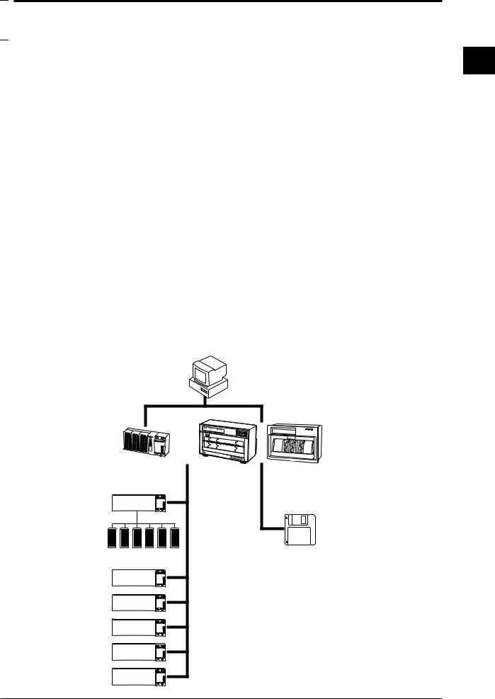
Created from a completely new concept that is based on modular architecture, this group of next generation data acquisition systems is called DARWIN (Data Acquistion and Recording Windows).
Today many data acquisition networks are increasingly being linked together. More than ever before, large volume, high speed, accurate, easy-to-use communication functions are essential in many disciplines.
In the world of measurement and control where the number of measurement points has increased sharply, the ability to acquire information from a large number of points easily and economically is crucial. Interfacing to a personal computer allows simplified utilization of the information while improving quality and efficiency.
DARWIN is based on a unique, new concept to meet these needs. The art of measurement is revolutionized by DARWIN which integrates functions of conventional recording and data logging.
Most existing data acquisition equipment has been the all-in-one type in which the measurement section and display/recording section are contained in one box. While this simplifies operation on the one hand, it is difficult to adapt to changes in the measurement environment and also makes expansion difficult.
DARWIN uses a data acquisition engine and remote I/O modules which are completely separate from each other. It is an entirely new product line which quickly and flexibly copes with various restrictive conditions and changes in specifications.
Supported by a personal computer, a whole line-up can be created starting with the data acquisition systems DA series which performs data logging. For example, using a printer as the output device, the equipment becomes a hybrid recorder (DR series).
Two models are available in the DR series: the DR230 and DR240. The DR 230 is a desk-top hybrid recorder, and the DR240 is a panel-mount hybrid recorder (component type).
Personal computer
CH=001 RANGE=TC TYPE-T
DA100
DR230 DR240
Subunit
Input/output |
FD |
|
modules |
|
|
|
|
|
Extension cables (max. length 500m)
1
Configuration System
IM DR232-01E |
1-1 |
|


 1.2 Product Overview
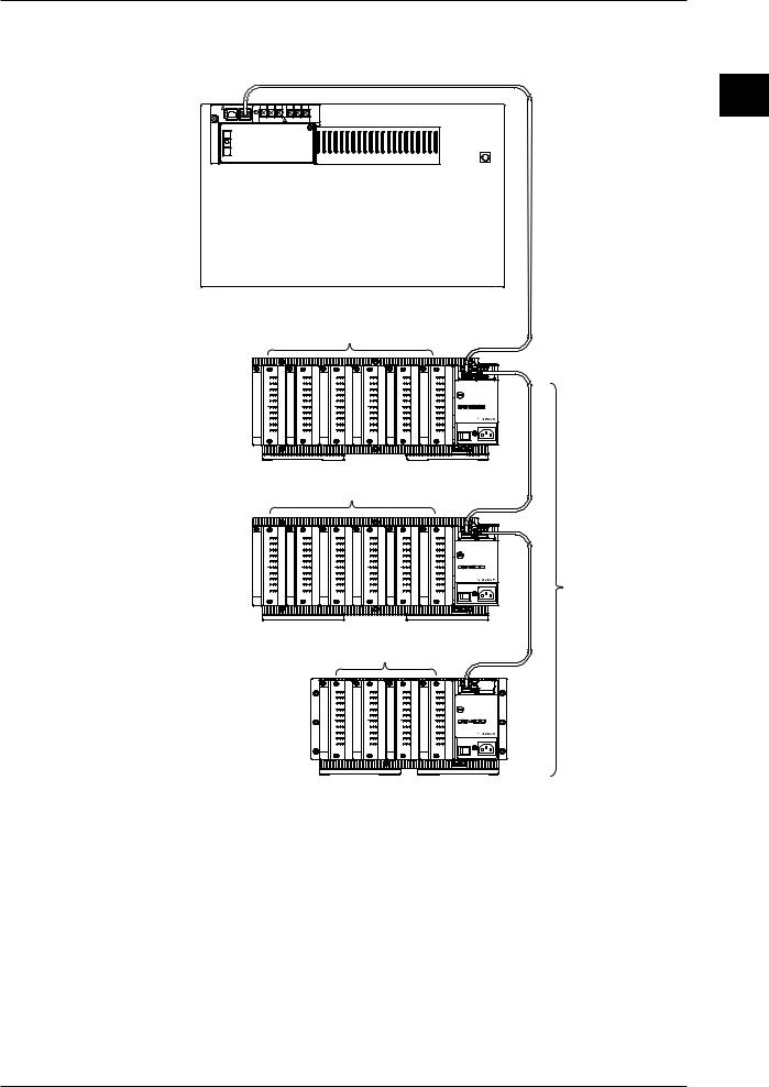
This product is a hybrid recorder which can record and measure from small-scale 10-ch data up to widely distributed 300-ch multi-point data.
The number of measurement points can be expanded up to a maximum of 300-ch by connecting up to six subunits (DS400/DS600) to a main unit (DR232/242). Using dedicated extension cables between units, interconnections can be extended up to 500 m. Since measured objects scattered over a wide area can be wired fast and with a minimum of wiring, a flexible, extensive measurement system can be configured. The input modules to be incorporated in the DR232/242 or DS400/600 can be selected from the following, to suit your measurement conditions:
• Universal input module and DCV/TC/DI input module
Temperature, DC voltage and contact signals can be measured, but cannot be connected to the main unit.
• mA-input Module
This module can directly measure DC currents ranging from -20 mA to 20 mA since it contains shunt resistors. It cannot be connected to a system's main unit.
• Power Monitor Module
This module can measure the effective voltage, effective current, active power, reactive power, apparent power, frequency, power factor and phase angle for an AC voltage or AC current input. It is available in either a single-phase or three-phase model. This module cannot be connected to a system's main unit.
• Strain Input Module
This module can measure strain. It is available in either a model with built-in 120or 350-Ω bridge resistors or a model with NDIS terminals where bridge resistors are connected externally. The module cannot be connected to a system's main unit.
• Pulse Input Module
This module can measure pulses. It cannot be connected to a system's main unit.
• Digital input module
This module can measure contact signals. It cannot be connected to a system’s main unit.
• Communication interface module
This module is necessary when communicating with a personal computer. Measurement conditions can be set and data acquired via the communication interface (GP-IB, RS-232-C, etc.) of this dule. This module can only be connected to the main unit.
• Alarm module
This module can output alarm signals as contact signals. The module can be connected to the main unit or the subunit.
• DI/DO module
This module allows a signal to be output in the case of alarm, failure, or chart end and a remote control signal for the product to be input. The module can be connected to the main unit or the subunit but only one module in all units.
Note
When the following handling is done, it is necessary to carry out “system construction” to operate the instrument correctly. After executing system construction, confirm the module information. For details, see page 9-16.
•Connection (including addition or replacement)/removal of subunits, or unit number setting (see page 3- 7)
•Mounting (including addition or replacement)/removal of modules
1-2 |
IM DR232-01E |
|
1.2 Product Overview
Connection example
Main unit DR232/DR242
 Extension cable
10ch Universal Input module
|
b -/B +/A |
b -/B +/A |
b -/B +/A |
b -/B +/A |
b -/B +/A |
|
b -/B +/A |
|
CH 1 |
CH 1 |
CH 1 |
CH 1 |
CH 1 |
CH 1 |
|
|
CH 2 |
CH 2 |
CH 2 |
CH 2 |
CH 2 |
CH 2 |
|
Subunit |
CH 3 |
CH 3 |
CH 3 |
CH 3 |
CH 3 |
CH 3 |
|
CH 5 |
CH 5 |
CH 5 |
CH 5 |
CH 5 |
CH 5 |
STATUS |
|
|
CH 4 |
CH 4 |
CH 4 |
CH 4 |
CH 4 |
CH 4 |
|
DS600 |
CH 6 |
CH 6 |
CH 6 |
CH 6 |
CH 6 |
CH 6 |
|
|
|
|
|
|
|
SUB UNIT |
|
|
CH 7 |
CH 7 |
CH 7 |
CH 7 |
CH 7 |
CH 7 |
|
|
CH 8 |
CH 8 |
CH 8 |
CH 8 |
CH 8 |
CH 8 |
|
|
CH 9 |
CH 9 |
CH 9 |
CH 9 |
CH 9 |
CH 9 |
100 - 240V 50/60Hz 70VA MAX |
|
CH10 |
CH10 |
CH10 |
CH10 |
CH10 |
CH10 |
P O W E R |
|
|
10ch Universal Input module |
|||||
|
b -/B +/A |
b -/B +/A |
b -/B +/A |
b -/B +/A |
b -/B +/A |
|
b -/B +/A |
|
CH 1 |
CH 1 |
CH 1 |
CH 1 |
CH 1 |
CH 1 |
|
|
CH 2 |
CH 2 |
CH 2 |
CH 2 |
CH 2 |
CH 2 |
|
Subunit |
CH 3 |
CH 3 |
CH 3 |
CH 3 |
CH 3 |
CH 3 |
|
CH 4 |
CH 4 |
CH 4 |
CH 4 |
CH 4 |
CH 4 |
STATUS |
|
|
CH 5 |
CH 5 |
CH 5 |
CH 5 |
CH 5 |
CH 5 |
|
DS600 |
CH 6 |
CH 6 |
CH 6 |
CH 6 |
CH 6 |
CH 6 |
|
CH 8 |
CH 8 |
CH 8 |
CH 8 |
CH 8 |
CH 8 |
SUB UNIT |
|
|
CH 7 |
CH 7 |
CH 7 |
CH 7 |
CH 7 |
CH 7 |
|
|
CH 9 |
CH 9 |
CH 9 |
CH 9 |
CH 9 |
CH 9 |
100 - 240V 50/60Hz 70VA MAX |
|
CH10 |
CH10 |
CH10 |
CH10 |
CH10 |
CH10 |
P O W E R |
|
10ch Universal Input module |
|
|||||
|
|
|
b -/B +/A |
b -/B +/A |
b -/B +/A |
|
b -/B +/A |
|
|
|
CH 1 |
CH 1 |
CH 1 |
CH 1 |
|
|
|
|
CH 2 |
CH 2 |
CH 2 |
CH 2 |
|
|
|
|
CH 3 |
CH 3 |
CH 3 |
CH 3 |
|
Subunit |
|
|
CH 4 |
CH 4 |
CH 4 |
CH 4 |
STATUS |
|
|
CH 6 |
CH 6 |
CH 6 |
CH 6 |
|
|
|
|
|
CH 5 |
CH 5 |
CH 5 |
CH 5 |
|
DS400 |
|
|
CH 8 |
CH 8 |
CH 8 |
CH 8 |
SUB UNIT |
|
|
|
CH 7 |
CH 7 |
CH 7 |
CH 7 |
|
|
|
|
CH 9 |
CH 9 |
CH 9 |
CH 9 |
100 - 240V 50/60Hz 55VA MAX |
|
|
|
CH10 |
CH10 |
CH10 |
CH10 |
P O W E R |
Up to 6 subunits can be connected
1
Configuration System
IM DR232-01E |
1-3 |
|

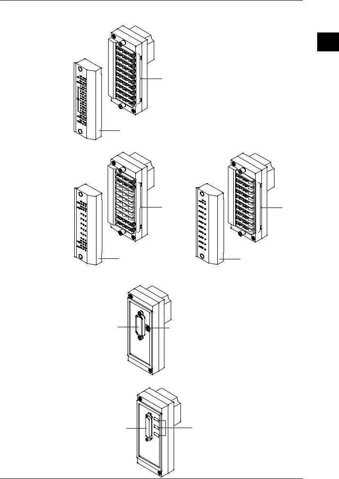
 1.3 Names of Parts
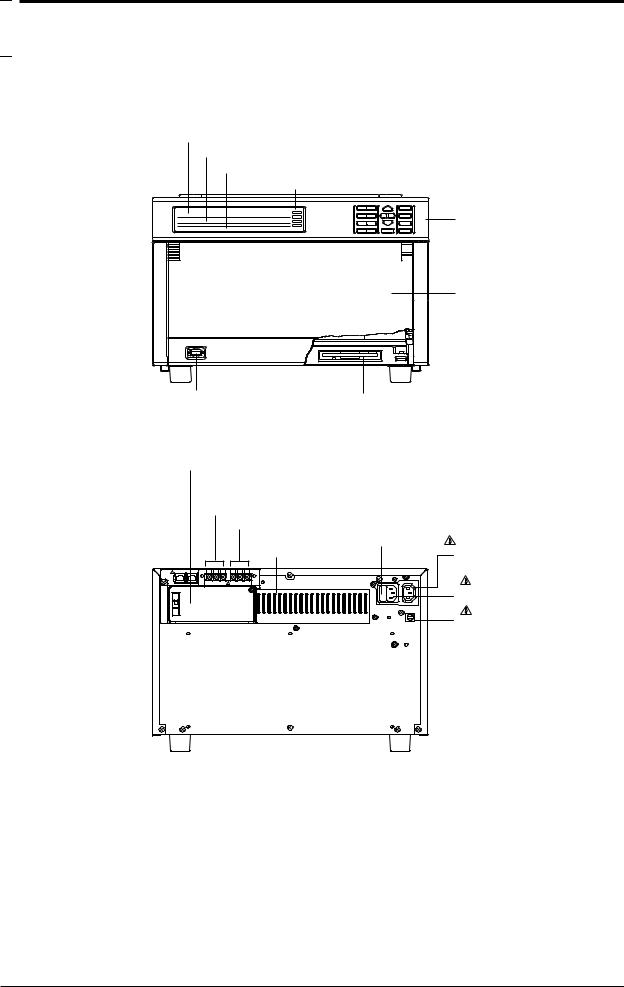
DR232 Main Unit (desk-top hybrid recorder)
Front
Main display (See chapter 4.)
Sub-display 1 (See chapter 4.)
Sub-display 2 (See chapter 4.)
Status indicator
Operation panel
(See chapters 3 to 12.)
 Handle to open/close
  the front door
Front door
Power switch (See page 3-22) Floppy disk drive (Only for DR232-1)
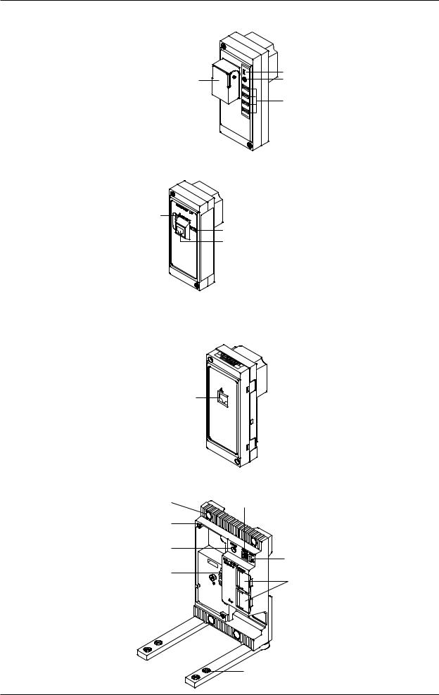
Rear |
|
|
Vacant slot with cover |
|
|
(for communication interface, |
|
|
alarm, or DI/DO modules) |
|
|
Failure output terminals |
|
|
Chart end output terminals |
|
|
Power fuse ( |
See page 13-2) |
|
Heat sink fins |
AC outlet(Au xiliary |
|
|
||
|
for DS400/DS600 |
|
|
: |
See page 3-29) |
|
Power connector |
|
|
( |
See page 3-29) |
|
Function grounding |
|
|
terminal |
|
1-4 |
IM DR232-01E |
|
1.3 Names of Parts
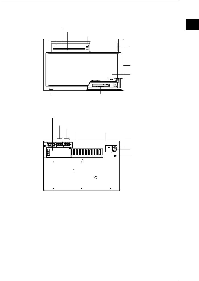
DR242 Main Unit (panel-mount hybrid recorder)
Front
Main display (See chapter 4.)
Sub-display 1 (See chapter 4.)
Sub-display 2 (See chapter 4.)
Status indicator
Operation panel
(Located behind the front door. See chapters 3 to 12.)
Handle to open/close the front door
Front door
Power switch
(Located inside the front door. See page 3-22.)
Rear
Vacant slot with cover
(for communication interface, alarm, or DI/DO modules)
Failure output terminals
Chart end output terminals Heat sink fins
Power fuse  (See page 13-2) (located in the main unit)
AC outlet(Auxiliary for DS400/DS600
: See page 3-30)
Power terminals with a cover (  See page 3-30)
Function grounding terminal
1
Configuration System
IM DR232-01E |
1-5 |
|
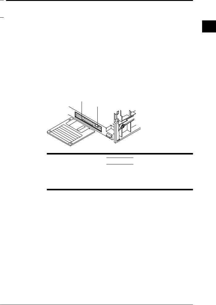
1.3 Names of Parts
Subunit DS400
Module connector |
|
|
|
Lid covering the extension |
|
Switch to set the |
cable connector |
|
|
||
unit number |
Status indicator |
|
|
||
Screw holes for |
Installation holes |
|
module installation |
||
|
Power switch
Function grounding 
 Power connector terminal (below power switch)
Feet
 Holes for fastening the feet
Subunit DS600
Installation holes
Module connector
|
|
Lid covering the |
|
|
|
extension cable |
|
|
|
connector |
|
Screw holes for |
|
Status indicator |
|
module installation |
|||
|
|||
Switch to set |
|
|
|
the unit number |
Power switch |
|
|
Function grounding |
Power connector |
||
|
|||
terminal (below power switch) |
|||
|
|||
|
Feet |
|
|
|
|
Holes for fastening |
|
|
|
the feet |
|
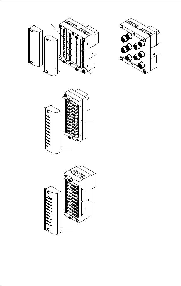
Input modules
10-ch Universal input module (DU100-11/DU100-12)
DU100-11 |
DU100-12 |
Screw |
Clamp |
|
terminal |
||
terminal |
||
|
Cover |
Cover |
|
The 20-ch Universal input modules (DU100-21/DU100-22) and the 30-ch Universal input modules (DU100-31/DU100-31) are similar to the ones shown above.
1-6 |
IM DR232-01E |
|

1.3 Names of Parts
10-ch DCV/TC/DI input module (DU200-11/DU200-12)
DU200-11 |
DU200-12 |
Screw |
Clamp |
|
terminal |
||
terminal |
||
|
Cover |
Cover |
|
The 20-ch DCV/TC/DI input modules (DU200-21/DU200-22) and the 30-ch DCV/TC/DI input modules (DU200-31/DU200-31) are similar to the ones shown above.
mA input module (DU300-11/DU300-12)
1
Configuration System
Screw |
Clamp |
|
terminal |
||
terminal |
||
|
Cover |
Cover |
|
AC input module (DU400-12/22)
Wire clip
Clamp terminal
Cover
IM DR232-01E |
1-7 |
|
1.3 Names of Parts
Strain input module (DU500-12/DU500-13/DU500-14)
DU500-12/DU500-13 |
DU500-14 |
Gauge method setup switch
NDI terminal
Cover
Clamp terminal
Pulse input module (DU600-11)
Screw terminal
Cover
Digital input module (DU700-11)
Screw terminal
Cover
1-8 |
IM DR232-01E |
|
1.3 Names of Parts
I/O Terminal Modules
DI/DO module (DT100-11)
Screw terminal
Cover
Alarm module (DT200-11/DT200-21)
DT200-11 |
DT200-21 |
Screw |
Screw |
terminal |
terminal |
Cover |
Cover |
Communication Module
GP-IB module (DT300-11)
1
Configuration System
GP-IB connector |
Switch to set |
|
|
|
the address |
RS-232-C module (DT300-21)
RS-232-C connector |
Switches to set |
|
communication parameters |
IM DR232-01E |
1-9 |
|
1.3 Names of Parts
RS-422-A/RS-485 Module (DT300-31)
|
ON/OFF switch of built-in terminating resistor |
RS-422-A/RS-485 terminal |
LED |
Switches to set communication parameters
Ethernet module (DT300-41)
Status indicator
Switch to set mode
10BASE-T port
Extender Module/Extender Base
Extender Module (DV100-011)
Extension cable connector
EXTENDER |
I/F |
|
|
I/F |
|
Extender Base (DV100-012)
Inatallation |
Slot number setup switch |
holes |
|
Screw holes for |
|
module installation |
|
Power indicator |
|
|
Terminator on/off switch |
Module connector |
|
|
Lid covering the extension |
Holes for fastening the feet
1-10 |
IM DR232-01E |
|

 1.4 Floppy Disk
A floppy disk drive is provided with the DR232-1 and DR242-1.
Applicable Floppy Disks
3. 5-inch floppy disks can be used for this instrument. They can also be formatted on this instrument.
•2HD type: 1.2 MB or 1.44 MB (MS-DOS format)
•2DD type; 720 MB (MS-DOS format)
Inserting a Floppy Disk into the Drive
Insert the floppy disk into the floppy disk drive, shutter side first and with the label face up.
Make sure that the floppy disk is inserted until the eject button pops up.
Removing the Floppy Disk from the Drive
Make sure that the access indicator is not lit, then push the eject button to remove the floppy disk.
access indicator
eject button
1
Configuration System
CAUTION
If the floppy disk is removed when the access indicator is still lit, damage to the magnetic head of the floppy disk drive or to data saved on the floppy disk may result. Before removing the floppy disk, always make sure that the access indicator is OFF.
General Precautions Regarding Handling of Floppy Disk
For general precautions regarding handling of floppy disks, refer to the instruction manual provided with the disk.
IM DR232-01E |
1-11 |
|


 2.1 Display Functions
The inter-active front panel display consists of three rows. The first row is the main display, and the second and third row are sub-display 1 and 2 respectively.
Monitor Mode and Status Display
Monitor Mode
•Auto Mode
This mode can be set for the main display, sub-display 1 and sub-display 2. Measurement values of all channels will be consecutively displayed with update interval.
•Manual Mode
This mode can be set for the main display, sub-display 1 and sub-display 2. Measurement values of a single channel will be displayed. The display update interval is the same as the measurement interval (refer to page 2-4).
•Manual Mode
This mode can be set for the main display. When choosing this display, the measurement values of 5 consecutive channels will be displayed as a page using also sub-display 1 and 2. The display update interval is the same as the measurement interval (refer to page 2-4).
•Alarm Search Mode
This mode can be set for the main display, sub-display 1 and sub-display 2. Channels at which an alarm occurred will be searched for and their measurement values displayed. The display update interval is 2 seconds.
•Bargraph Mode
This mode can be set for sub-display 1. Measurement values which are shown on the main display will be shown as a bargraph. The display update interval is the same as the interval of the main display.
•Alarm Status Mode
This mode can be set for sub-display 1 and 2. The display will show per channel whether or not an alarm occurred (refer to page 2-13). On one display the alarm status of a maximum of 30 channels can be monitored (depending on the number of input channels). The display update interval is 0.5 seconds.
•Relay Status Mode
This mode can be set for sub-display 1 and 2. The display will show the operating status of internal switches/alarm output relays (refer to page 2-13). On one display a maximum of 30 relay statuses can be monitored. The display update interval is 1 second.
•Clock Mode
This mode can only be set for sub-display 2. The current date and time are shown.
•Displaying the Selected Mode
To the right of sub-display 1 the currently selected display mode is shown for a specific display.
Status Display
Indicators at the right side of the display will light up to show that recording is in progress (refer to page 2-5), alarms are occuring (refer to page 2-13), keys are locked (refer to page 2-17) and chart needs to be replaced (refer to page 2-18).
Remote/Local Status Display
The status of remote/local control will be show on sub-display 2. Keys cannot be operated in remote control.
2
Functions
IM DR232-01E |
2-1 |
|

2.1 Display Functions
Display for Setting the Type of Input, Computation and Recording Conditions
Menus for setting each of the following functions will be displayed.
•measurement input functions (refer to page 2-3)
•recording functions (refer to page 2-5)
•alarm functions (refer to page 2-13)
•calculation functions (refer to page 2-16)
•event/action function, key-lock function and external in/output function (refer to page 2-17, 18)
Display for Setting Fundamental Functions
Menus for performing fundamental settings will be displayed.
2-2 |
IM DR232-01E |
|


 2.2 Measurement Input Functions
Input Type
DC Voltage
Measurements can be done after selecting the measurement range per channel. The minimum range is 20mV, the maximum range is 50V.
Thermocouple
Measurements can be done after selecting the type of thermocouple per channel. The available types are R, S, B, K, E, J, T, L, U, N, W and KPvsAU7FE.
Reference Junction Compensation (RJC) can be set to either use Internal RJC (INT) or External RJC (EXT) per channel.
Burnout function can be set OFF per channel or it can be selected in which direction the trend line will move if burnout occurs (right or left)
Resistance Temperature Detector
Measurements can be done after selecting the type of resistance temperature detector (RTD) per channel. The available 17 types are Pt100(1mA), Pt100(2mA), JPt100(1mA), JPt100(2mA), Pt50(2mA), Ni100(1mA)SAMA, Ni100(1mA)DIN, Ni120(1mA), J263*B, Cu10GE, Cu10L&N, Cu10WEED, Cu10BAILEY, Pt100 (1mA) high resolution, Pt100 (2mA) high resolution, JPt100 (1mA) high resolution and JPt100 (2mA) high resolution.
Contact Input
The type of contact input can be selected from voltage level input or contact input, and recording can be set ON or OFF per channel. In case of the voltage level input a voltage level up to 2.4V results in recording OFF, whereas a voltage level of 2.4V or more results in recording ON.
DC Currents
DC currents ranging from -20 mA to 20 mA can be measured by means of the built-in 250-Ω shunt resistors.
AC Voltages/Currents
The effective voltage, effective current, active power, reactive power, apparent power, frequency, power factor and phase angle can be measured. The measuring range is common to all terminals. The input terminals of the module with this input mode, unlike those of modules with other input modes, are not consistent with a setup screen in terms of the channel number.
Strain
The module for this input mode supports the single-gauge, single-gauge three-wire (not yet supported by the DU500-14 module), adjacent-side two-gauge, opposed-side two-gauge and fourgauge methods. If you have connected any new strain gauge or changed the measuring range, go through initial balancing before starting measurement.
Pulses
The module for this input mode can measure the number of pulses per second on a channel basis or detect the on/off states by means of any variations occurring in the instantaneous value every second. Once you connect the pulse input module, you can sum up values without the need for the computing function.
Skipping Input Channels
This function allows skipping measurement, recording and display of channels you are not using.
Measurement, recording and display will not be done for the skipped channels.
Reference Junction Compensation (RJC)
This function is to be used when measuring temperatures using thermocouples. The voltage generated by a thermocouple depends on the temperature of the spot of measurement and the reference junction temperature. Reference junction compensation is a function which compensates the temperature at the side of the measurement instrument to 0 degrees C.
To compensate for the environmental temperature an internal circuit can be selected, or compensation by a fixed compensation voltage value (external) can be set.
2
Functions
IM DR232-01E |
2-3 |
|
2.2 Measurement Input Functions
Scan Interval
•The duration of time (one scan) in which the measurement of all channels is carried out, is called the scan interval.
•This interval can be set to any value from 0.5 second to 60 seconds. The shortest is 300 ch/500 ms (varies with the shortest measurement period of the input module).
A/D Integration Time
This instrument measures the input signal after putting it through an A/D converter. In order to minimize the noise imposed on the input signal, specific integration times exist.
The integration time can be selected from 20ms (50Hz), 16.7ms (60Hz) and 100ms (10Hz). When “AUTO” is selected, the integration time will be automatically decided according to the 50/ 60Hz frequency of the power supply.
AUTO does not function if the instrument is the subunit (DS400/DS600) of the DC power supply model (Selecting “AUTO” will set the A/D integration time to 20 ms (50 Hz)). If you are using the instrument on a 60-Hz power supply, set the A/D integration time to 16.7 ms (60Hz).
Input Filter
A filter can be set ON/OFF to reduce normal mode noise. Effects on normal mode noise are as follows depending on the filter being ON/OFF (theoretical values).
Attenuation
1Hz
0dB
–20dB
–40dB
–60dB
–80dB
Frequency
10Hz 50Hz100Hz 300Hz
 Slope:–20dB/dec
Filter ON 
 Filter OFF
 Slope:–60dB/dec
–100dB
2-4 |
IM DR232-01E |
|
Loading...