


Digital Indicating Controller
UTAdvanced
Digital Indicating Controller |
UT75A / UT55A / UT52A / UT35A / UT32A |
|
||||||||
Program Controller |
UP55A / UP35A / UP32A |
|
||||||||
Digital Indicator with Alarms |
UM33A |
|
|
|
|
|
|
|
|
|
|
|
|
|
|
|
|||||
|
|
|
|
|
|
|
|
|
|
|
|
|
|
|
|
|
|
|
|
|
|
Bulletin 05P01A02-01EN
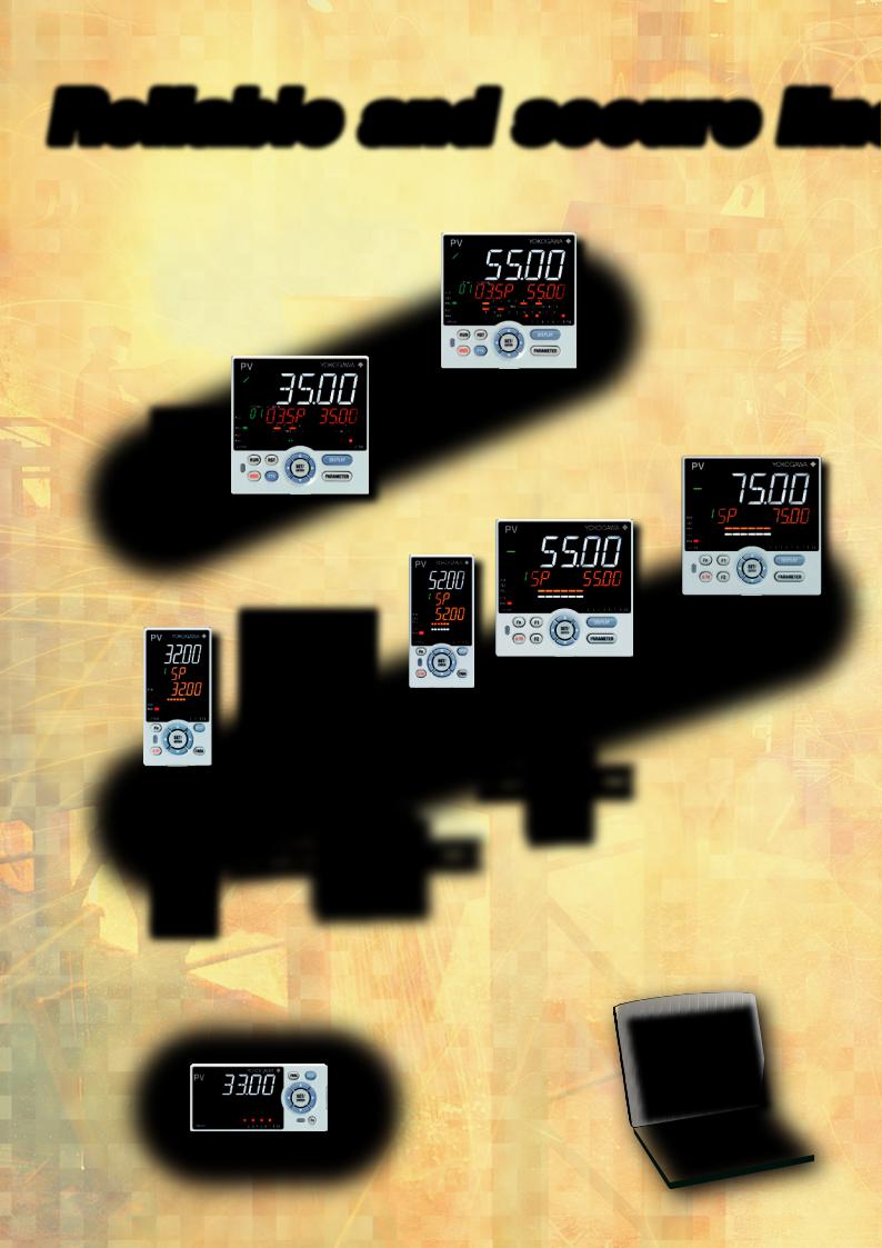
Reliable and secure lin
Welcome new members: 2-loop and DIN rail models, and the UP32A UP55A
Program Controller
UP35A
UP32A
UT75A
UT55A
UT52A
UT35A
UT32A
Digital Controller
|
UT52A/MDL |
|
UT55A/MDL |
|
Rail Mounting Controller |
|
UT32A/MDL |
UT32A-D |
UT35A/MDL |
(Dual-loop type) |
DIN Rail Mounting Controller |
Con guration and Programming Software
LL50A
UM33A
Digital Indicator with Alarms
2
eup
Tools and |
Operation and |
functions that |
clear display that |
go easy on your |
go easy on the |
equipment |
user |
A variety |
Helpful |
of functions, and |
ladder sequence |
easy-to-connect |
control |
communication |
function |
Reliability • RoHS/WEEE
• NEMA4*/IP66 Front Panel * Hose down
172608
CSA C22.2 61010-1 UL61010-1
 Space saving options
•1/8th DIN 2-loop controller (UT32A-D)
•CC-Link communication available in a 48 x 96 mm (1/8 DIN) size
•1/8th DIN Program controller (UP32A)
•DIN rail mounting controller (/MDL option)
 More UP55A program patterns
• 99 program patterns (/AP option)
3
Tools and functions that go easy on your equipment
Setting and managing parameters
Easily edit settings from a PC while the unit is mounted on the controller board.
Settings are accessed through a dedicated adapter on the front panel. Maintenance of Ethernet-equipped controllers can be handled remotely.
Control board |
(Powered) |
Optical communication adapter and dedicated cable (Light loaderTM)
To USB port
•Set up parameters
•Controller data read/write/compare
•Data management
•Print parameters and data, and create reports
•Con gure user defaults
Set up right out of the box
To USB port
No power cable
required  LL50A Parameter Setting Software
Dedicated cable
With DIN rail mountable controllers (/MDL option), used to perform maintenance when powered.
Free software now available on the web for converting GREEN series parameters to UTAdvanced.
Can be supported with a single spare unit
Universal Input and Output
Supports different sensors, heaters, and actuators
TC |
|
mV |
4 to 20 mA current |
V |
|
mA |
Voltage pulse |
|
|
RTD |
Relay contact |
|
2-wire |
|
|
|
|
Motor operated valve* |
|
transmitter |
|
|
|
|
|
|
|
|
|
|
|
|
*Select a position proportional model |
|
|
|
|
|
|
|
|
|
|
|
|
|
for motorized valve control output. |
Universal Inputs |
Universal Control Outputs |
|||||
Gets you back home. Fast.
Shorter recovery time User defaults function
The LL50A lets you con gure user default values.
Ever get lost in a maze of con guration changes? Now you can restore user-personalized default parameters. Recover quickly without disturbing operations.
Easily restored by key operation
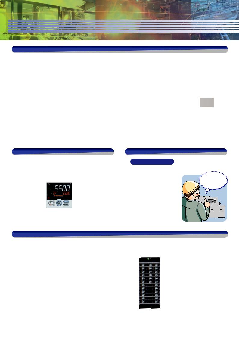
Save space on the panel and control board
Side-by-side close mounting on DIN rails in the board
Status display (LED)
Green:Normal
Red: Abnormal
• Ambient temperature: -10 to 50 °C
(0 to 50 °C with CC-Link installed)
DIN rail |
• 2-loop control in a single unit |
(UT32A-D/MDL)
• Displays controller and I/O status
UT32A/MDL
UT52A/MDL
UT32A-D/MDL
4

Operation and clear display that go easy on the user
Bright & Easy to Read Active Color LCD Display
Full size
PV display
(text height: 21.55 mm)
5
digit display
14
segment display
UT55A 1/4 DIN (96×96mm)size |
UT52A 1/8 DIN (48×96mm)size |
Active Color PV Display
See the status of your process conditions INSTANTLY!
Normal According to… |
|
• Alarms |
Alarm |
• Deviation values |
|
Display color changes! |
|
• Measured values |
|
• Contact input |
|
|
|
• Choice of xed white or red
Navigation guides and keys make it easy to operate |
Fast one-touch operations |
Controller will guide the key you press. |
Programmable Function Keys |
Navigation Guide
Navigation Keys
You can assign frequently used operations (start/stop, remote/local, etc.) and parameter entry screens (PID value, etc.) to function keys for one-touch availability.
Move freely (up/down/left/right)
between parameters!
UT series
5
A variety of functions, and easy-to-connect communication
Communication protocol
Connect to PLCs easily without programming!
Modbus/TCP
Modbus
RTU/ASCII
Ladder communication
PC-Link
Open Network
PLC • Recipe management
• Remote monitoring
DeviceNet
You can easily set setpoints (SP),
PID, and alarms from a PLC.
Serial gateway function |
Modbus slave |
UTAdvanced with RS-485 communication
Space-saving built-in CC-Link models
• UT52A, UT32A, UM33A, UT52A/MDL, UT32A/MDL
Modbus/TCP
|
|
|
|
|
|
|
|
|
FA-M3V |
|
||||||||
|
|
|
|
|
|
|
|
|
|
|
|
|
|
|
|
|
|
SMARTDAC+ |
|
|
|
|
|
|
|
|
|
PLC |
|
|
GX10/GX20 |
||||||
|
|
|
|
|
|
|
|
|
|
|
|
|
|
|
|
|
|
Ethernet |
|
|
|
|
|
|
|
|
|
|
|
|
|
|
|
|
|
|
|
|
|
|
|
|
|
|
|
|
|
|
|
|
|
|
|
|
|
|
|
|
|
|
|
|
|
|
|
|
|
|
|
Ethernet-serial Gateway Function |
RS-485 |
||||
|
|
|
|
|
|
|
|
|
|
|
|
|
|
|
|
|
|
|
|
|
|
|
|
|
|
|
|
|
|
|
|
|
|
|
|
|
|
Modbus TCP, a protocol that allows the controller to connect to Ethernet network and have the ability to exchange data with the computers or devices on that network.
•Gateway function allows RS-485 Modbus devices to communicate via Ethernet.
•Physical layer: 10 BASE-T/100 BASE-TX
•Max. number of connection : 2
UTAdvanced with RS-485 communication
Peer to Peer
The use of the ladder sequence program makes it possible to exchange analog data and status data between communication-capable UTs.
Example: A UT in which an input error occurs sends a signal to another UT to enable that UT switch to MAN operation, thus shifting the whole system into a safe mode. In such a case, the safety mechanism can be built into the UTAdvanced and is not required in the host system.
* Create ladder sequence programs by the LL50A Parameter Setting software (sold separately).
 RS485
RS485
1 |
2 |
4 |
15 |
32 |
Up to 4 master units, total 32 units
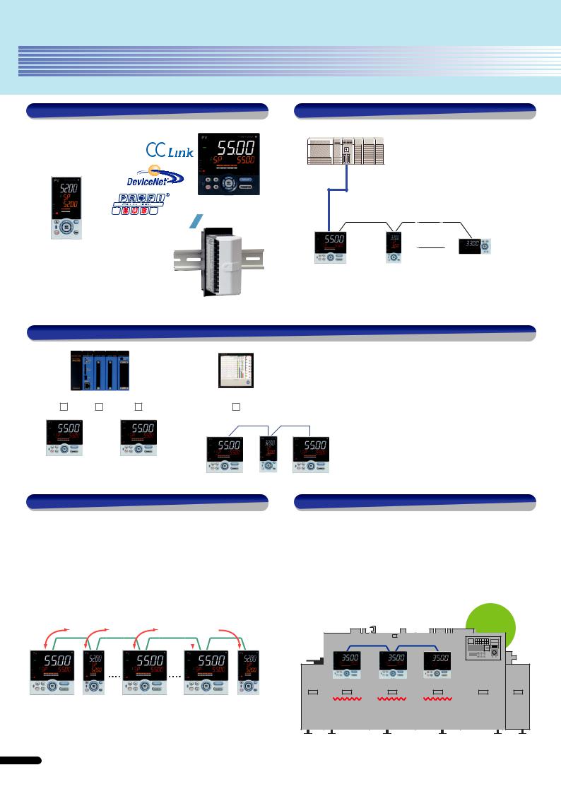
Coordinated operation
Coordinated operation: This function syncs operation of the slave with that of the master through Yokogawa's proprietary communication protocol.
•Finely adjust the temperature setting of the slave with the bias and ratio
•Upstream PLC or other device not needed for tuning
•No programming means fewer engineering manhours
|
|
Continuous |
|
|
furnace |
|
RS-485 |
|
Slave UT35A |
Slave UT35A |
Master UP35A |
Zone 3 |
Zone 2 |
Zone 1 |
SP is zone 1 |
SP is zone 1 |
SP is programmed |
SP minus 5 °C |
SP plus 10 °C |
|
6
 Loading...