


 Loading...
User’s
Manual
Models GX10/GX20/GP10/GP20
Paperless Recorder
Communication Command
User’s Manual
IM 04L51B01-17EN
3rd Edition

Introduction
Thank you for purchasing the SMARTDAC+ GX10/GX20/GP10/GP20 (hereafter referred to as the GX and GP) Series.
This manual explains the dedicated commands for the GX/GP. To ensure correct use, please read this manual thoroughly before beginning operation.
Notes
•The contents of this manual are subject to change without prior notice as a result of continuing improvements to the instrument’s performance and functions.
•Every effort has been made in the preparation of this manual to ensure the accuracy of its contents. However, should you have any questions or find any errors, please contact your nearest YOKOGAWA dealer.
•Copying or reproducing all or any part of the contents of this manual without the permission of YOKOGAWA is strictly prohibited.
•The TCP/IP software of this product and the documents concerning it have been developed/created by YOKOGAWA based on the BSD Networking Software, Release 1 that has been licensed from the Regents of the University of California.
Trademarks
•vigilantplant is a registered trademark of Yokogawa Electric Corporation.
•SMARTDAC+ is a trademark of Yokogawa Electric Corporation.
•Microsoft and Windows are registered trademarks or trademarks of Microsoft Corporation in the United States and/or other countries.
•Adobe and Acrobat are registered trademarks or trademarks of Adobe Systems Incorporated.
•Company and product names that appear in this manual are registered trademarks or trademarks of their respective holders.
•The company and product names used in this manual are not accompanied by the registered trademark or trademark symbols (® and ™).
Revisions
December 2012 |
1st Edition |
February 2013 |
2nd Edition |
May 2013 |
3rd Edition |
3rd Edition: May 2013 (YK)
All Right Reserved, Copyright © 2012 - 2013, Yokogawa Electric Corporation
IM 04L51B01-17EN
i

How to Use This Manual
This manual explains the dedicated communication commands for the GX/GP and how to use them. For details on the features of the GX/GP and how to use it, see the following manuals.
•Models GX10/GX20/GP10/GP20 Paperless Recorder First Step Guide (IM 04L51B0102EN)
•Models GX10/GX20/GP10/GP20 Paperless Recorder User’s Manual (IM 04L51B0101EN)
Conventions Used in This Manual
Unit
KDenotes 1024. Example: 768K (file size)
kDenotes 1000.
Markings
Improper handling or use can lead to injury to the user or damage to the instrument. This symbol appears on the instrument to indicate that the user must refer to the user’s manual for special instructions. The same symbol appears in the corresponding place in the user’s manual to identify those instructions. In the manual, the symbol is used in conjunction with the word “WARNING” or “CAUTION.”
WARNING Calls attention to actions or conditions that could cause serious or fatal injury to the user, and precautions that can be taken to prevent such occurrences.
CAUTION Calls attention to actions or conditions that could cause light injury to the user or cause damage to the instrument or user’s data, and precautions that can be taken to prevent such occurrences.
Note Calls attention to information that is important for the proper operation of the instrument.
ii
IM 04L51B01-17EN

Contents
Introduction................................................................................................................................................ |
i |
How to Use This Manual........................................................................................................................... |
ii |
Conventions Used in This Manual............................................................................................................ |
ii |
Chapter 1 Using Dedicated Commands (General)
1.1 |
Operations over an Ethernet Network................................................................................. |
1-1 |
|
|
1.1.1 |
Preparing the Instrument........................................................................................................ |
1-1 |
|
1.1.2 |
Sending Commands and Receiving Responses.................................................................... |
1-1 |
1.2 |
Operations over the Serial Interface.................................................................................... |
1-2 |
|
|
1.2.1 |
Preparing the Instrument........................................................................................................ |
1-2 |
|
1.2.2 |
Sending Commands and Receiving Responses.................................................................... |
1-2 |
|
1.2.3 |
RS-232 Connection Procedure............................................................................................... |
1-3 |
|
1.2.4 |
RS-422/485 Connection Procedure........................................................................................ |
1-6 |
Chapter 2 Commands and Responses
2.1 |
Command Transmission and GX/GP Responses................................................................ |
2-1 |
|
|
2.1.1 |
General Communication......................................................................................................... |
2-1 |
|
2.1.2 |
Command Types and Functions............................................................................................. |
2-1 |
|
2.1.3 |
Command Syntax................................................................................................................... |
2-1 |
|
2.1.4 |
GX/GP Responses................................................................................................................. |
2-4 |
2.2 |
List of Commands................................................................................................................ |
2-5 |
|
|
2.2.1 |
Setting Commands................................................................................................................. |
2-5 |
|
2.2.2 |
Output Commands.................................................................................................................. |
2-6 |
|
2.2.3 |
Operation Commands............................................................................................................. |
2-6 |
|
2.2.4 |
Communication Control Commands....................................................................................... |
2-7 |
|
2.2.5 |
Instrument Information Commands........................................................................................ |
2-7 |
|
2.2.6 |
Conditions for Executing Commands..................................................................................... |
2-7 |
2.3 |
Parameters.......................................................................................................................... |
2-8 |
|
|
2.3.1 |
Measuring Range Parameters................................................................................................ |
2-8 |
|
2.3.2 |
Parameter Notation and Range.............................................................................................. |
2-8 |
|
2.3.3 |
Specifying a Range................................................................................................................. |
2-8 |
2.4 |
Setting Commands.............................................................................................................. |
2-9 |
|
2.5 |
Output Commands............................................................................................................. |
2-44 |
|
2.6 |
Operation Commands........................................................................................................ |
2-47 |
|
2.7 |
Communication Control Commands.................................................................................. |
2-51 |
|
2.8 |
Instrument Information Output Commands........................................................................ |
2-52 |
|
2.9 |
Responses to Commands................................................................................................. |
2-53 |
|
|
2.9.1 |
Affirmative Response (For commands other than output request commands).................... |
2-53 |
|
2.9.2 |
Negative Response.............................................................................................................. |
2-53 |
|
2.9.3 |
Data Output Response......................................................................................................... |
2-54 |
|
2.9.4 |
Output in Response to RS-422/485 Commands.................................................................. |
2-56 |
2.10 |
ASCII Output Format......................................................................................................... |
2-57 |
|
|
2.10.1 |
Most Recent Channel Data (FData)..................................................................................... |
2-57 |
|
2.10.2 |
Most Recent (DO Channel) Status (FRelay)........................................................................ |
2-58 |
|
2.10.3 |
Internal Switch Status (FRelay)............................................................................................ |
2-59 |
|
2.10.4 |
Users Who Are Currently Logged In (FUser)........................................................................ |
2-60 |
|
2.10.5 |
All Users Who Are Currently Logged In (FUser)................................................................... |
2-61 |
|
2.10.6 |
Instrument Address (FAddr).................................................................................................. |
2-62 |
|
2.10.7 |
GX status (FStat).................................................................................................................. |
2-63 |
|
2.10.8 |
Alarm Summary (FLog)........................................................................................................ |
2-64 |
|
2.10.9 |
Message Summary (FLog)................................................................................................... |
2-65 |
|
2.10.10 |
Event log (FLog)................................................................................................................... |
2-66 |
|
2.10.11 |
Error Log (FLog)................................................................................................................... |
2-67 |
|
2.10.12 |
Address Setting Log (FLog).................................................................................................. |
2-68 |
|
2.10.13 |
General Communication Log (FLog).................................................................................... |
2-69 |
|
2.10.14 |
Modbus Communication Log (FLog).................................................................................... |
2-70 |
|
2.10.15 |
FTP Client Log (FLog).......................................................................................................... |
2-71 |
|
2.10.16 |
SNTP (Time Adjustment) Client Log (FLog)......................................................................... |
2-72 |
|
2.10.17 |
E-Mail Client Log (FLog)....................................................................................................... |
2-73 |
|
2.10.18 |
Web Log (FLog).................................................................................................................... |
2-74 |
|
2.10.19 External Storage Medium and Internal Memory File List (FMedia)...................................... |
2-75 |
|
1
2
App
IM 04L51B01-17EN |
iii |

Contents
|
2.10.20 |
External Storage Medium Free Space (FMedia).................................................................. |
2-75 |
|
2.10.21 |
Setting Data (FCnf)............................................................................................................... |
2-76 |
|
2.10.22 |
Decimal Place and Unit Information (FChInfo)..................................................................... |
2-76 |
|
2.10.23 |
System Configuration (FSysConf)........................................................................................ |
2-77 |
|
2.10.24 |
Instrument Manufacturer (_MFG)......................................................................................... |
2-78 |
|
2.10.25 |
Instrument’s Product Name (_INF)....................................................................................... |
2-78 |
|
2.10.26 |
Instrument’s Basic Specifications (_COD)............................................................................ |
2-78 |
|
2.10.27 |
Instrument’s Firmware Version Information (_VER)............................................................. |
2-79 |
|
2.10.28 |
Instrument’s Option Installation Information (_OPT)............................................................. |
2-79 |
|
2.10.29 |
Instrument’s Temperature Unit and Daylight Saving Time Installation Information (_TYP).. |
2-80 |
|
2.10.30 |
Instrument’s Error Number Information (_ERR).................................................................... |
2-80 |
|
2.10.31 |
Instrument’s Unit Configuration Information (_UNS or _UNR)............................................. |
2-81 |
|
2.10.32 |
Instrument’s Module Configuration Information (_MDS or MDR)......................................... |
2-82 |
2.11 |
Format of the Data Block of Binary Output........................................................................ |
2-83 |
|
|
2.11.1 |
Most Recent Channel Data (FData)..................................................................................... |
2-83 |
|
2.11.2 |
Channel FIFO Data (FFifoCur)............................................................................................. |
2-86 |
|
2.11.3 |
FIFO Data Read Range (FFifoCur)...................................................................................... |
2-87 |
Appendix
Appendix 1 |
ASCII Character Codes................................................................................................... |
App-1 |
Appendix 2 |
Login Procedure.............................................................................................................. |
App-2 |
|
When Using the Login Function........................................................................................................ |
App-2 |
|
When Not Using the Login Function................................................................................................. |
App-3 |
Appendix 3 Output Flow Chart of External Storage Medium Files and File Lists............................... |
App-4 |
|
|
Example for Outputting File aaaa.dtd................................................................................................ |
App-4 |
|
Example for Outputting a File List..................................................................................................... |
App-5 |
Appendix 4 |
FIFO Data Output Flow Chart.......................................................................................... |
App-6 |
|
Overview of the FIFO Buffer............................................................................................................. |
App-6 |
|
Example of FIFO Buffer Operation.................................................................................................... |
App-6 |
Appendix 5 |
Check Sum Calculation Method...................................................................................... |
App-7 |
iv
IM 04L51B01-17EN

Chapter 1 Using Dedicated Commands (General)
1.1Operations over an Ethernet Network
You can control the GX/GP by sending commands from a PC over an Ethernet network. There are various types of commands: setting commands, output commands, operation commands, communication control commands, and instrument information output commands.
1.1.1Preparing the Instrument
GX/GP Configuration
Configure the GX/GP to connect to the Ethernet network that you want to use. For instructions on how to configure the GX/GP, see section 1.16, “Configuring the Ethernet Communication Function“ in the Models GX10/GX20/GP10/GP20 Paperless Recorder User’s Manual (IM 04L51B01-01EN).
PC
The PC that you will use must meet the following requirements.
•The PC is connected to the Ethernet network that you want to use.
•The PC can run programs that you have created (see section 1.1.2, “Sending Commands and Receiving Responses,” below).
1.1.2Sending Commands and Receiving Responses
Programs
When you send a command to the GX/GP, it will return a response. You can control the GX/GP by writing a program that sends commands and processes responses and then executing the program. You need to create the programs.
Example: If you send the commands “FSnap,GET” from your PC to the GX/GP, the GX/GP will return the snapshot data of its screen.
For details on commands and responses, see chapter 2, “Commands and Responses.”
Notes on Creating Programs
•When Not Using the Login Function
You can start using commands immediately after communication is established with the GX/GP.
•When Using the Login Function
Log in to the GX/GP using a system administrator account or a normal user account that is registered in the GX/GP. Log in by connecting to the GX/GP and then sending the “CLogin” command.
1
(General) Commands Dedicated Using
IM 04L51B01-17EN |
1-1 |

1.2Operations over the Serial Interface
You can control the GX/GP by sending commands from a PC through the serial interface. There are various types of commands: setting commands, output commands, operation commands, communication control commands, and instrument information output commands. Except for a few special commands, the commands are the same as those used over an Ethernet network.
1.2.1Preparing the Instrument
Connection
See section 1.2.3, “RS-232 Connection Procedure,” or section 1.2.4, “RS-422/485
Connection Procedure.”
GX/GP Configuration
Configure the GX/GP to use serial communication. For instructions on how to configure the GX/GP, see section 1.17, “Configuring the Serial Communication Function (/C2 and /C3 options)“ in the Models GX10/GX20/GP10/GP20 Paperless Recorder User’s Manual (IM 04L51B01-01EN).
PC
The PC that you will use must meet the following requirements.
•The PC is connected to the GX/GP through the serial interface.
•The PC can run programs that you have created (see section 1.2.2, “Sending Commands and Receiving Responses,” below).
1.2.2Sending Commands and Receiving Responses
Programs
When you send a command to the GX/GP, it will return a response. You can control the GX/GP by writing a program that sends commands and processes responses and then executing the program. You need to create the programs.
Example: If you send the commands “FSnap,GET” from your PC to the GX/GP, the GX/GP will return the snapshot data of its screen.
For details on commands and responses, see chapter 2, “Commands and Responses.”
Notes on Creating Programs
•For RS-232
When you connect a PC to the GX/GP through the serial interface, the GX/GP will be ready to receive commands.
•For RS-422/485
The device that receives an open command (ESC O) from a PC will be ready to receive commands. The connection will close in the following situations.
•When the GX/GP receives a connection-close command (ESC C).
•When another device is opened.
Example: If you open the device at address 1 and then open the device at address 2, the connection with the device at address 1 will be closed automatically.
1-2 |
IM 04L51B01-17EN |
1.2 Operations over the Serial Interface
1.2.3RS-232 Connection Procedure
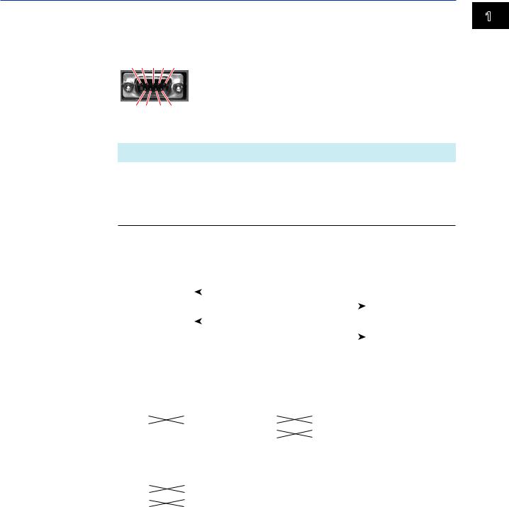
Connect a cable to the 9-pin D-sub RS-232 connector.
Connection
• Connector pin arrangement and signal names
5 4 3 2 1
6 7 8 9
Each pin corresponds to the signal indicated below. The following table shows the signal name, RS-232 standard, JIS, and ITU-T standard signals.
Pin1 |
Signal Name |
|
Name |
Meaning |
|
|
JIS |
ITU-T |
RS-232 |
|
|
2 |
RD |
104 |
BB(RXD) |
Received data |
Input signal to the GX/GP. |
3 |
SD |
103 |
BA(TXD) |
Transmitted data |
Output signal from the GX/GP. |
5 |
SG |
102 |
AB(GND) |
Signal ground |
Signal ground. |
7 |
RS |
105 |
CA(RTS) |
Request to send |
Handshaking signal when receiving data from the |
|
|
|
|
|
PC. Output signal from the GX/GP. |
8 |
CS |
106 |
CB(CTS) |
Clear to send |
Handshaking signal when receiving data from the |
|
|
|
|
|
PC. Input signal to the GX/GP. |
1Pins 1, 4, 6, and 9 are not used.
•Signal direction
|
|
|
RS [Request to send...Ready to receive] |
|
7 |
|
|||||
|
|
|
|
|
|||||||
PC |
|
|
CS [Clear to send...Ready] |
|
|
|
8 |
GX/GP |
|||
|
|
|
|
||||||||
|
|
SD [Send data] |
|
|
|
|
|
|
3 |
||
|
|
|
|
|
|
|
|
|
|||
|
|
|
|
|
|
|
|
|
|||
|
|
|
RD [Received data] |
|
|
2 |
|
||||
|
|
|
|
|
|||||||
|
|
|
|
|
|
|
|
|
|
|
|
• Connection example
• OFF-OFF/XON-XON |
• CS-RS(CTS-RTS) |
|
|
|||||||||||
PC |
|
|
|
GX/GP |
PC |
|
GX/GP |
|||||||
|
SD |
|
|
|
3 |
SD |
|
|
|
SD |
|
3 |
SD |
|
|
RD |
|
|
|
2 |
RD |
|
RD |
|
2 |
RD |
|||
|
RS |
|
|
|
7 |
RS |
|
RS |
|
7 |
RS |
|||
|
CS |
|
|
|
8 |
CS |
|
CS |
|
8 |
CS |
|||
|
|
|
|
|
|
|||||||||
|
SG |
|
|
|
5 |
SG |
|
|
SG |
|
5 |
SG |
|
|
|
|
|
|
|
|
|||||||||
• XON-RS(XON-RTS) |
|
|
|
|
|
|
||||||||
|
PC |
|
|
|
GX/GP |
The connection of RS on the PC and CS |
||||||||
|
SD |
|
|
|
3 |
SD |
|
|||||||
|
RD |
|
|
|
2 |
RD |
on the GX/GP is not necessary. However, |
|||||||
|
RS |
|
|
|
7 |
RS |
we recommend that you wire them so that |
|||||||
|
CS |
|
|
|
8 |
CS |
||||||||
|
SG |
|
|
|
5 |
SG |
|
the cable can be used in either direction. |
||||||
|
|
|
|
|||||||||||
1
(General) Commands Dedicated Using
IM 04L51B01-17EN |
1-3 |

1.2 Operations over the Serial Interface
Handshaking
When using the RS-232 interface for transferring data, it is necessary for equipment on both sides to agree on a set of rules to ensure the proper transfer of data. The set of rules is called handshaking. Because there are various handshaking methods that can be used between the GX/GP and the PC, you must make sure that the same method is chosen by both the GX/GP and the PC.
You can choose any of the four methods on the GX/GP in the table below.
Hand- |
Data transmission control |
|
Data Reception Control |
|
||
shaking |
(Control used when sending data to a PC) |
(Control used when receiving data from |
||||
|
|
|
|
a PC) |
|
|
|
Software |
Hardware |
No |
Software |
Hardware |
No |
|
Handshaking |
Handshaking |
handshaking |
Handshaking |
Handshaking |
handshaking |
OFF-OFF |
|
|
Yes |
|
|
Yes |
XON-XON |
Yes1 |
|
|
Yes3 |
|
|
XON-RS |
Yes1 |
|
|
|
Yes4 |
|
CS-RS |
|
Yes2 |
|
|
Yes4 |
|
Yes Supported.
1 Stops transmission when X-OFF is received. Resume when X-ON is received.
2Stops sending when CS (CTS) is false. Resumes when it is true.
3Sends X-OFF when the receive data buffer is 3/4 full. Sends X-ON when the receive data buffer is 1/4th full.
4Sets RS (RTS) to False when the receive data buffer is 3/4 full. Sets RS (RTS) to True when the receive data buffer becomes 1/4 full.
•OFF-OFF
Data transmission control
There is no handshaking between the GX/GP and the PC. The “X-OFF” and “X-ON” signals received from the PC are treated as data, and the CS signal is ignored.
Data reception control
There is no handshaking between the GX/GP and the PC. When the received buffer becomes full, all of the data that overflows are discarded.
RS = True (fixed).
•XON-XON
Data transmission control
Software handshaking is performed between the GX/GP and the PC. When an “X-OFF” code is received while sending data to the PC, the GX/GP stops the data transmission. When the GX/GP receives the next “X-ON” code, the GX/GP resumes the data transmission. The CS signal received from the PC is ignored.
Data reception control
Software handshaking is performed between the GX/GP and the PC. When the amount of area of the received buffer used reaches to 192 bytes, the GX/GP sends an “X-OFF” code. When the amount of area decreases to 64 bytes, the GX/GP sends an “X-ON” code.
RS = True (fixed).
•XON-RS
Data transmission control
The operation is the same as with XON-XON.
Data reception control
Hardware handshaking is performed between the GX/GP and the PC. When the amount of area of the received buffer used reaches to 192 bytes, the GX/GP sets “RS=False.” When the amount of area decreases to 64 bytes, the GX/GP sets “RS=True.”
1-4 |
IM 04L51B01-17EN |
1.2 Operations over the Serial Interface
•CS-RS
Data transmission control
Hardware handshaking is performed between the GX/GP and the PC. When the CS signal becomes False while sending data to the PC, the GX/GP stops the data transmission. When the CS signal becomes True, the GX/GP resumes the data transmission. The “X-OFF” and “X-ON” signals are treated as data.
Data reception control
The operation is the same as with XON-RS.
Note
•The PC program must be designed so that the received buffers of both the GX/GP and the PC do not become full.
•If you select XON-XON, send the data in ASCII format.
1
(General) Commands Dedicated Using
IM 04L51B01-17EN |
1-5 |
1.2Operations over the Serial Interface
1.2.4RS-422/485 Connection Procedure
Connect a cable to the terminal.
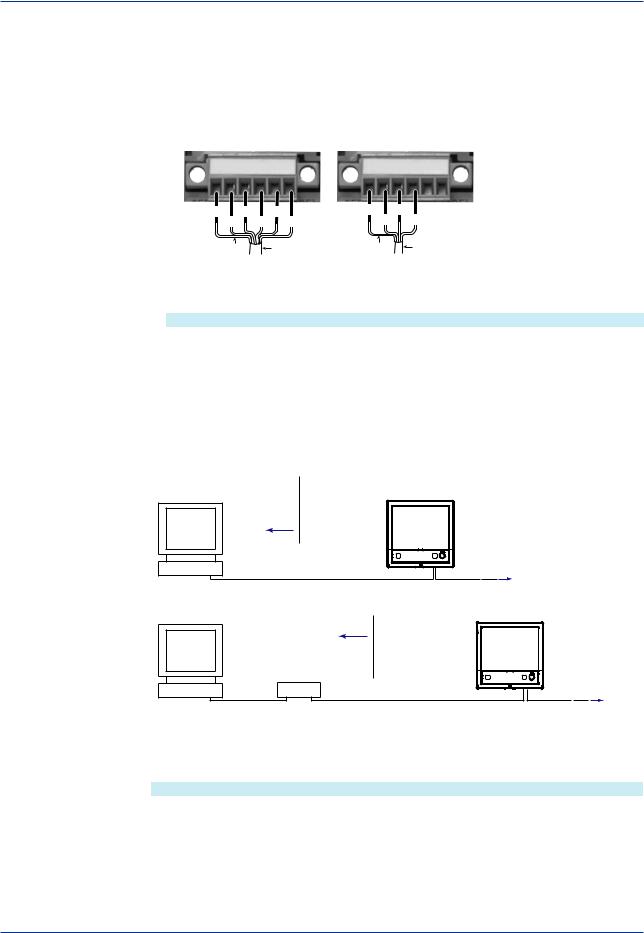
Connection
• Connecting the Cable
As shown in the figure below, remove approximately 6 mm of the covering from the end of the cable to expose the conductor. Keep the exposed section from the end of the shield within 5 cm.
Four-wire system |
Two-wire system |
|
|
||
FG SG SDB+ SDA– RDB+RDA– |
|
|
|
|
|
FG SG SDB+ SDA– RDB+RDA– |
|||||
FG |
SDB+ RDB+ |
FG |
SDB+ |
||
|
SG |
SDA− RDA− |
|
SG |
SDA− |
Electric potential |
Shield Electric potential Shield |
Recommended torque |
of the shield |
of the shield |
for tightening the screw: 0.2 N•m |
• Signal names
Each terminal corresponds to the signal indicated below.
Signal Name |
Meaning |
FG |
Frame ground of the GX/GP. |
SG |
Signal ground. |
SDB+ |
Send data B (+). |
SDA– |
Send data A (–). |
RDB+ |
Receive data B (+). |
RDA– |
Receive data A (–). |
Connecting to the host device
The figure below illustrates the connection of the GX/GP to a host device. If the port on the host device is an RS-232 interface, connect a converter.
Host computer |
RS-422/485 |
or host device |
terminal on the GX/GP |
Host device side |
|
RS-422/485 |
|
|
RS-422/485 |
Host computer |
terminal on the GX/GP |
|
Host device side |
Converter |
|
RS-232 |
RS-422/485 |
Connection example to the host device
A connection can be made with a host device having a RS-232, RS422, or RS-485 port. In the case of RS-232, a converter is used. See the connection examples below for a typical converter terminal. For details, see the manual that comes with the converter.
RS-422/485 Port |
Converter |
SDA(–) |
TD(–) |
SDB(+) |
TD(+) |
RDA(–) |
RD(–) |
RDB(+) |
RD(+) |
SG |
SHIELD |
FG |
EARTH |
|
There is no problem of connecting a 220-Ω terminator at either end if YOKOGAWA’s PLCs |
|
or temperature controllers are also connected to the communication line. |
1-6 |
IM 04L51B01-17EN |

1.2 Operations over the Serial Interface
•Four-wire system
Generally, a four-wire system is used to connect to a host device. In the case of a fourwire system, the transmission and reception lines need to be crossed over.
|
Terminator (external) 120 Ω 1/2W or greater |
|
Host device |
RS-422/485 |
|
side |
terminal on the GX/GP |
|
SDA( – ) |
SDA– |
SDA– |
(SDA–) |
(SDA–) |
|
SDB( + ) |
SDB+ |
SDB+ |
(SDB+) |
(SDB+) |
|
RDA( – ) |
RDA– |
RDA– |
(RDA–) |
(RDA–) |
|
RDB( + ) |
RDB+ |
RDB+ |
(RDB+) |
(RDB+) |
|
SG |
SG |
SG |
(SG) |
(SG) |
|
|
FG |
FG |
|
#1 |
#2 |
Terminator (external)
SDA–
(SDA–)
SDB+
(SDB+)
RDA–
(RDA–)
RDB+
(RDB+)
SG
(SG)
FG
#n
(#n 32)
32)
Do not connect terminators to #1 through #n-1.
• Two-wire system
Connect the transmission and reception signals with the same polarity on the RS-422/485 terminal block. Only two wires are used to connect to the external device.
|
|
Terminator (external) 120 Ω 1/2W or greater |
Terminator (external) |
|
|
||
Host device |
|
RS-422/485 |
|
|
terminal on the GX/GP |
|
SDA( – ) |
SDA– |
SDA– |
SDA– |
|
(A–) |
(A–) |
(A–) |
|
|
SDB( + ) |
SDB+ |
SDB+ |
SDB+ |
|
(B+) |
(B+) |
(B+) |
|
|
RDA( – ) |
RDA– |
RDA– |
RDA– |
|
RDB+ |
RDB+ |
RDB+ |
|
|
RDB( + ) |
|
|||
SG |
SG |
SG |
|
|
SG |
|
|||
(SG) |
(SG) |
(SG) |
|
|
|
FG |
FG |
FG |
|
|
#1 |
#2 |
#n |
31) |
|
|
|
(#n |
Do not connect terminators to #1 through #n-1.
Note
•The method used to eliminate noise varies depending on the situation. In the connection example, the shield of the cable is connected only to the GX/GP’s ground (one-sided grounding). This is effective when there is a difference in the electric potential between the computer’s ground and the GX/GP’s ground. This may be the case for long distance
communications. If there is no difference in the electric potential between the computer’s ground and the GX/GP’s ground, the method of connecting the shield also to the computer’s ground may be effective (two-sided grounding). In addition, in some cases, using two-sided grounding with a capacitor connected in series on one side is effective. Consider these possibilities to eliminate noise.
•When using the two-wire interface (Modbus protocol), the 485 driver must be set to high impedance within 3.5 characters after the last data byte is sent by the host computer.
1
(General) Commands Dedicated Using
IM 04L51B01-17EN |
1-7 |

1.2 Operations over the Serial Interface
Serial interface converter
The recommended converter is given below.
SYSMEX RA CO.,LTD./MODEL RC-770X, LINE EYE/SI-30FA, YOKOGAWA/ML2
Some converters not recommended by Yokogawa have FG and SG pins that are not isolated. In this case, do not follow the diagram on the previous page (do not connect anything to the FG and SG pins). Especially in the case of long distance communications, the potential difference that appears may damage the GX/GP or
cause communication errors. For converters that do not have the SG pin, they can be used without using the signal ground. For details, see the manual that comes with the converter.
On some non-recommended converters, the signal polarity may be reversed (A/B or +/- indication). In this case, reverse the connection.
For a two-wire system, the host device must control the transmission driver of the converter in order to prevent collisions of transmit and received data. When using the recommended converter, the driver is controlled using the RS (RTS) signal on the RS-232.
When instruments that support only the RS-422 interface exist in the system
When using the four-wire system, up to 32 GX/GPs can be connected to a single host device. However, this may not be true if instruments that support only the RS-422 interface exist in the system.
When YOKOGAWA’s recorders that support only the RS-422 interface exist in the system
The maximum number of connection is 16. Some of YOKOGAWA’s conventional recorders (HR2400 and µR, for example) only support the RS-422 driver. In this case, only up to 16 units can be connected.
Note
In the RS-422 standard, 10 is the maximum number of connections that are allowed on one port
(for a four-wire system).
Terminator
When using a multidrop connection (including a point-to-point connection), connect a terminator to the GX/GP if the GX/GP is connected to the end of the chain. Do not connect a terminator to a GX/GP in the middle of the chain. In addition, turn ON the terminator on the host device (see the manual of the host device). If a converter is being used, turn ON its terminator. The recommended converter is a type that has a built-in terminator.
Select the appropriate terminator (120 Ω), indicated in the figure, according to the characteristic impedance of the line, the installation conditions of the instruments, and so on.
1-8 |
IM 04L51B01-17EN |

Chapter 2 Commands and Responses
2.1Command Transmission and GX/GP Responses
2.1.1General Communication
The GX/GP can work with various applications through the use of commands. The communication that is achieved through commands is referred to as “general communication.”
2.1.2Command Types and Functions
The following types of commands are available. The first character of command names represents the command type. For example, in the command “SRangeAI,” “S” represents the command type. The second and subsequent characters represent the contents of commands.
Type |
Description |
Operation commands |
Commands that start with “O.” These commands are used |
Example: OSetTime |
to operate the GX/GP. |
Setting commands |
Commands that start with “S.” These commands change |
Example: SRangeAI |
the GX/GP settings. |
Output commands |
Commands that start with “F.” These commands cause the |
Example: FData |
GX/GP to output measured data and other types of data. |
Communication Control commands Commands that start with “C.” These commands control the
Example: CCheckSum |
communication with the GX/GP. |
Instrument information output |
Commands that start with an underscore. These commands |
commands |
cause the GX/GP to output its instrument information. |
Example: _MFG |
|
2.1.3 Command Syntax A Single Command
A single command consists of a command name, parameters, delimiters, and terminator. The command name is written in the beginning, and parameters follow. Delimiters are used to separate the command name from parameters and between each parameter. A delimiter is a symbol that indicates a separation. A terminator is attached to the end of a command.
Command name,parameter 1,parameter 2 terminator
Delimiters
Example of a Command
SRangeAI,0001,VOLT,2V,OFF,-15000,18000,0
Commands in a Series (Setting commands only)
You can send multiple setting commands in a series. When writing a series of commands, separate each command with a sub delimiter. A sub delimiter is a symbol that indicates a separation. A terminator is attached to the end of the series. The maximum number of bytes that can be sent at once is 8000 bytes (8000 characters).
Command name,parameter 1,parameter 2;command name,parameter1 terminator
(Command 1) |
|
|
(Command 2) |
|
|
|
Sub delimiter |
|
|
|
2
Responses and Commands
IM 04L51B01-17EN |
2-1 |

2.1 Command Transmission and GX20 Responses
Notes on Writing Commands in a Series
•Only setting commands can be written in a series.
•Queries (see the next section) cannot be written in a series.
•If there is an error in one of the commands in a series, the commands before it are canceled, and those after it are not executed.
Example of a Command
SRangeAI,0001,VOLT,2V,OFF,-15000,18000,0;SRangeAI,0002,SKIP
Queries
Queries are used to inquire the GX/GP settings. To send a query, append a question mark to the command name or parameter. When the GX/GP receives a query, it returns the relevant setting as a character string in an appropriate syntax. Queries can be used on some of the available setting and operation commands.
Command name? terminator
Command name,parameter1? terminator
Examples of Queries and Responses
Query |
Example of Responses |
SRangeAI? |
SRangeAI,0001,VOLT,2V,OFF,–20000,20000,0 |
|
SRangeAI,0002,............................................................... |
|
.......................................................................................... |
SRangeAI,0001? |
SRangeAI,0001,VOLT,2V,OFF,–20000,20000,0 |
Command Names
A command name is a character string consisting of up to 16 alphanumeric characters. The first character represents the command type.
Notes on Writing Commands Names
•Command names are not case sensitive.
•Spaces before the character string are ignored.
2-2 |
IM 04L51B01-17EN |

2.1 Command Transmission and GX20 Responses
Parameters
Parameters are characteristic values that are attached to commands.
Notes on Writing Parameters
•Write parameters in their appropriate order.
•Spaces around and in the middle of parameters are ignored. Exception is the character strings that users specify.
•You can omit the setting command parameters that do not need to be changed from their current settings. If you omit parameters, write only the delimiters.
Example: SRangeAI,0001,,,,,1800,0 terminator
•If parameters are omitted and there are multiple delimiters at the end of the command, those delimiters can be omitted.
Example: SRangeAI,0001,VOLT,2V,,,,terminator -> SRangeAI,0001,VOLT, 2Vterminator
There are two types of parameters: predefined expressions and user-defined character strings.
How to Write User-Defined Character Strings (Parameters)
• Enclose user-defined character strings in single quotation marks.
Example The command for setting the channel 0001 tag to “SYSTEM1” is shown below.
STagIO,0001,'SYSTEM1'
•There are two types of user-defined character strings depending on the type of characters that can be used.
Character Strings Consisting Only of Characters in the ASCII Code Range (0x00 to 0x7f)
In this manual, applicable parameters are indicated with “ASCII.”
Example p3 Tag number (up to 16 characters, ASCII)
You can use alphanumeric characters and some of the symbols. For the ASCII characters that you can use, see appendix 1.
Character Strings Consisting of Characters in the UTF-8 Code Range
In this manual, applicable parameters are indicated with “UTF-8.”
Example p2 Tag (up to 32 characters, UTF-8)
UTF-8 codes include ASCII codes. You can use UTF-8 characters, including the ASCII characters above. For the ASCII characters that you can use, see appendix 1.
Delimiters
Commas are used as delimiters.
Sub delimiters
Semicolons are used as sub delimiters.
Terminators
“CR+LF” is used as a terminator, meaning “CR” followed by “LF.” Expressed in ASCII code, it is 0x0d0x0a.
2
Responses and Commands
IM 04L51B01-17EN |
2-3 |

2.1 Command Transmission and GX20 Responses
2.1.4GX/GP Responses
The GX/GP returns the following responses to commands.
•If the GX/GP successfully completes the processing of a received output request command, it outputs the requested data.
•If the GX/GP successfully completes the processing of a received command that is not an output request command, it outputs an affirmative response.
•If a command syntax error, setting error, or other error occurs, the GX/GP outputs a negative response.
For each command the GX/GP receives, it returns a single response. The controller (PC) side must process commands and responses in accordance with this command-response rule. If the command-response rule is not followed, the operation of the GX/GP is not guaranteed. For details on the response syntax, see 2.9 Responses to Commands.
2-4 |
IM 04L51B01-17EN |

2.2List of Commands
2.2.1Setting Commands
Command |
Setup Item (Required Options) |
Page |
Measurement Operation Setting Commands |
|
|
SScan |
Scan interval |
2-9 |
SScanGroup |
Scan group |
2-9 |
SModeAI |
AI module |
2-9 |
SModeDI |
DI module |
2-9 |
SScaleOver |
Detection of values that exceed |
2-9 |
|
the scale |
|
Recording Basic Setting Commands |
Page |
|
SMemory |
Recording mode |
2-10 |
SDispData |
Display data recording |
2-10 |
SEventData |
Event data recording |
2-10 |
Recording Channel Setting Commands |
Page |
|
SRecDisp |
Channel for recording display |
2-10 |
SRecEvent |
data |
2-11 |
Channel for recording event data |
||
SRecManual |
Channel for recording manual |
2-11 |
|
sampled data |
|
Batch Setting Commands |
Page |
|
SBatch |
Batch function |
2-11 |
STextField |
Batch text |
2-11 |
Data Save Setting Commands |
Page |
|
SDirectory |
Name of directory to save data |
2-11 |
SFileHead |
File header |
2-12 |
SFileName |
File naming rule |
2-12 |
SMediaSave |
Automatic data file saving |
2-12 |
SFileFormat |
Display/event data file format |
2-12 |
I/O Channel (AI/DI/DO) Setting Commands |
Page |
|
SRangeAI |
Measurement range of AI channel2-13 |
|
SRangeDI |
Measurement range of DI channel2-14 |
|
SRangeDO |
DO channel operation |
2-14 |
SMoveAve |
Moving average |
2-15 |
SBurnOut |
Behavior when a sensor burns out2-15 |
|
SRjc |
Reference junction compensation 2-15 |
|
SAlarmIO |
method |
|
Alarm |
2-15 |
|
SAlmHysIO |
Alarm hysteresis |
2-16 |
SAlmDlyIO |
Alarm delay time |
2-16 |
STagIO |
Tag |
2-16 |
SColorIO |
Channel color |
2-16 |
SZoneIO |
Waveform display zone |
2-17 |
SScaleIO |
Scale display |
2-17 |
SBarIO |
Bar graph display |
2-17 |
SPartialIO |
Partial expanded display |
2-17 |
SBandIO |
Color scale band |
2-17 |
SAlmMarkIO |
Alarm mark |
2-18 |
SValueIO |
Upper/lower limit display |
2-18 |
SCalibIO |
characters |
2-18 |
Calibration correction |
||
Math Channel Setting Commands |
Page |
|
SMathBasic |
Math action (/MT) |
2-19 |
SKConst |
Constant (/MT) |
2-20 |
SRangeMath |
Computation expression (/MT) |
2-20 |
STlogMath |
TLOG (/MT) |
2-20 |
SRolAveMath |
Rolling average (/MT) |
2-20 |
SAlarmMath |
Alarm (/MT) |
2-20 |
SAlmHysMath |
Alarm hysteresis (/MT) |
2-21 |
SAlmDlyMath |
Alarm delay time (/MT) |
2-21 |
STagMath |
Tag (/MT) |
2-21 |
SColorMath |
Channel color (/MT) |
2-21 |
SZoneMath |
Waveform display zone (/MT) |
2-21 |
SScaleMath |
Scale display (/MT) |
2-21 |
SBarMath |
Bar graph display (/MT) |
2-22 |
SPartialMath Partial expanded display (/MT) |
2-22 |
|
SBandMath |
Color scale band (/MT) |
2-22 |
SAlmMarkMath Alarm mark (/MT) |
2-22 |
|
Communication Channel Setting Commands |
Page |
|
SRangeCom |
Measurement range (/MC) |
2-23 |
SValueCom |
Preset operation (/MC) |
2-23 |
SWDCom |
Watchdog timer (/MC) |
2-23 |
SAlarmCom |
Alarm (/MC) |
2-24 |
SAlmHysCom |
Alarm hysteresis (/MC) |
2-24 |
SAlmDlyCom |
Alarm delay time (/MC) |
2-24 |
STagCom |
Tag (/MC) |
2-24 |
SColorCom |
Channel color (/MC) |
2-25 |
SZoneCom |
Waveform display zone (/MC) |
2-25 |
SScaleCom |
Scale display (/MC) |
2-25 |
SBarCom |
Bar graph display (/MC) |
2-25 |
SPartialCom |
Partial expanded display (/MC) |
2-25 |
SBandCom |
Color scale band (/MC) |
2-25 |
SAlmMarkCom |
Alarm mark (/MC) |
2-26 |
Alarm Setting Commands |
Page |
|
SAlmLimit |
Rate-of-change alarm interval |
2-26 |
SAlmSts |
Alarm display hold/nonhold |
2-26 |
Time Setting Commands |
Page |
|
STimer |
Timer |
2-26 |
SMatchTimer |
Match time timer |
2-27 |
Event Action Setting Commands |
Page |
|
SEventAct |
Event action |
2-27 |
Report Setting Commands |
Page |
|
SReport |
Report type (/MT) |
2-28 |
SRepData |
Report data (/MT) |
2-28 |
SRepTemp |
Report output (/MT) |
2-29 |
SRepCh |
Report channel (/MT) |
2-29 |
Display Setting Commands |
Page |
|
SLcd |
LCD |
2-29 |
SViewAngle |
View angle |
2-29 |
SBackColor |
Screen background color |
2-30 |
SGrpChange |
Automatic group switching time |
2-30 |
SAutoJump |
Jump default display operation |
2-30 |
SCalFormat |
Calendar display format |
2-30 |
SBarDirect |
Bar graph display direction |
2-30 |
IM 04L51B01-17EN |
2-5 |
2
Responses and Commands

2.2 List of Commands
SChgMonitor |
Value modification from the |
2-30 |
|
|
SMailTime |
Scheduled transmission times |
2-38 |
||
|
|||||||||
STrdWave |
monitor |
2-30 |
|
|
SSntpCnct |
SNTP client |
2-39 |
||
Trend waveform display |
|
|
SModClient |
Modbus client operation (/MC) |
2-39 |
||||
STrdScale |
Scale |
2-30 |
|
|
SModCList |
Modbus client connection |
2-39 |
||
STrdLine |
Trend line width, grid |
2-31 |
|
|
SModCCmd |
destination server (/MC) |
2-39 |
||
STrdRate |
Trend interval switching |
2-31 |
|
|
Modbus client transmission |
||||
STrdKind |
Trend type |
2-31 |
|
|
SServer |
|
command (/MC) |
2-40 |
|
|
|
|
Server function |
||||||
STrdPartial |
Partial expanded trend display |
2-31 |
|
|
|
||||
|
|
SKeepAlive |
Keepalive |
2-40 |
|||||
SMsgBasic |
Message writing |
2-31 |
|
|
|||||
|
|
STimeOut |
Communication timeout |
2-40 |
|||||
SGroup |
Display group |
2-31 |
|
|
|||||
|
|
SFtpFormat |
FTP server directory output format2-40 |
||||||
STripLine |
Display group trip line |
2-32 |
|
|
|||||
|
|
SModDelay |
Modbus server delay response |
2-40 |
|||||
SSclBmp |
Scale bitmap image usage |
2-32 |
|
|
|||||
|
|
SModLimit |
Modbus server connection limit |
2-40 |
|||||
SMessage |
Message |
2-32 |
|
|
|||||
System Setting Commands |
Page |
|
|
SModList |
IP address to allow connection to |
2-40 |
|||
STimeZone |
Time zone |
2-32 |
|
|
|
|
Modbus server |
|
|
|
|
Security Setting Commands |
Page |
||||||
SDateBasic |
Gradual time adjustment |
2-32 |
|
|
|||||
|
|
SSecurity |
Security function |
2-40 |
|||||
SDateFormat |
Date format |
2-32 |
|
|
|||||
|
|
SOpePass |
Password to unlock operation |
2-41 |
|||||
SDst |
Daylight saving time |
2-33 |
|
|
|||||
|
|
SOpeLimit |
Operation lock details |
2-41 |
|||||
SLang |
Language |
2-33 |
|
|
|||||
|
|
SUser |
|
User settings |
2-41 |
||||
STemp |
Temperature unit |
2-33 |
|
|
|
||||
|
|
SUserLimit |
Authority of user |
2-41 |
|||||
SDPoint |
Decimal point type |
2-33 |
|
|
|||||
|
|
Local Setting Commands |
Page |
||||||
SFailAct |
Fail relay (DO channel) operation |
2-33 |
|
|
|||||
|
|
SMonitor |
|
Monitor screen display |
2-41 |
||||
|
(/FL) |
|
|
|
|
||||
SFailSts |
Instrument status to output (/FL) |
2-34 |
|
|
SMultiPattern |
information |
2-42 |
||
|
|
Multi panel division |
|||||||
SPrinter |
Printer |
2-34 |
|
|
|||||
|
|
SMultiKind |
|
Multi panel |
2-42 |
||||
SLed |
LED indicator operation |
2-34 |
|
|
|
||||
|
|
SHomeMonitor |
Standard display information |
2-42 |
|||||
SSound |
Sound |
2-34 |
|
|
|||||
|
|
SHomeKind |
|
Standard display |
2-43 |
||||
SInstruTag |
Instruments tag |
2-34 |
|
|
|
||||
|
|
SFavoriteMonitorFavorite screen display |
2-43 |
||||||
SConfCmt |
Setting file comment |
2-34 |
|
|
|||||
|
|
|
|
|
information |
|
|||
SUsbInput |
USB input device |
2-34 |
|
|
SFavoriteKind |
2-43 |
|||
|
|
Favorite screen |
|||||||
Internal Switch Setting Commands |
Page |
|
|
||||||
|
|
|
|
|
|
|
|||
SSwitch |
Internal switch operation |
2-34 |
|
2.2.2 |
Output Commands |
|
|||
Serial Communication Setting Commands |
Page |
|
|
||||||
SSerialBasic Serial communication basics (/C2 |
2-35 |
|
|
Command |
Description |
Page |
|||
|
or /C3) |
|
|
|
|
|
|
|
|
SModMaster |
2-35 |
|
|
FData |
|
Outputs the most recent channel |
2-44 |
||
Modbus master (/C2/MC or /C3/ |
|
|
FRelay |
|
data |
|
|
||
SModMCmd |
MC) |
2-35 |
|
|
|
Outputs the most recent relay (DO 2-44 |
|||
Modbus master transmission |
|
|
FFifoCur |
channel) and internal switch status |
|
||||
|
command (/C2/MC or /C3/MC) |
Page |
|
|
Outputs channel FIFO data |
2-44 |
|||
Ethernet Communication Setting Commands |
|
|
FSnap |
|
Takes a snapshot |
2-44 |
|||
SIpAddress |
IP address information |
2-36 |
|
|
|
||||
|
|
FUser |
|
Outputs the user level |
2-44 |
||||
SClient |
Client function |
2-36 |
|
|
|
||||
|
|
FAddr |
|
Outputs the IP address |
2-45 |
||||
SDns |
DNS information |
2-36 |
|
|
|
||||
|
|
FStat |
|
Outputs the GX/GP status |
2-45 |
||||
SDhcp |
DHCP client |
2-36 |
|
|
|
||||
|
|
FLog |
|
Outputs the log |
2-45 |
||||
SFtpKind |
File to transfer via FTP |
2-37 |
|
|
|
||||
|
|
FMedia |
|
Outputs external storage medium |
2-45 |
||||
SFtpTime |
FTP transfer time shift |
2-37 |
|
|
FCnf |
|
and internal memory information |
|
|
SFtpCnct |
FTP client connection destination |
2-37 |
|
|
|
Outputs setting data |
2-46 |
||
SSmtpLogin |
server |
2-37 |
|
|
FChInfo |
|
Outputs decimal place and unit |
2-46 |
|
SMTP user authentication |
|
|
FSysConf |
information |
|
||||
SSmtpCnct |
SMTP client connection |
2-37 |
|
|
Queries the system configuration |
2-46 |
|||
SMailHead |
destination server |
2-37 |
|
|
|
|
and reconfigures modules |
|
|
Mail header (recipient address) |
|
|
|
|
|
|
|
||
SMailBasic |
Common section of the mail body |
2-38 |
|
2.2.3 |
Operation Commands |
|
|||
SMail |
Destination and behavior for each 2-38 |
|
|
Command |
Description |
Page |
|||
|
mail type |
|
|
|
|
|
|
|
|
SMailAlarm |
2-38 |
|
|
OSetTime |
Sets the time |
2-47 |
|||
Alarm notification mail target |
|
|
|||||||
|
|
ORec |
|
Starts or stops recording |
2-47 |
||||
|
channels |
|
|
|
|
||||
|
|
|
|
|
|
|
|
|
|
2-6 |
|
|
|
|
|
|
|
IM 04L51B01-17EN |
|
2.2 List of Commands
OAlarmAck |
Clears alarm output (alarm |
2-47 |
|
|
_TYP |
Outputs the instrument’s |
2-52 |
|||
|
||||||||||
OExecRec |
acknowledgement) |
2-47 |
|
|
|
|
temperature unit, and daylight |
|
||
Generates a manual trigger, |
|
|
|
|
saving time installation information |
|
||||
|
|
executes manual sample, takes a |
|
|
|
_ERR |
Outputs the instrument’s error |
2-52 |
||
|
|
snapshot, or causes a timeout |
|
|
|
|||||
OExecSNTP |
2-47 |
|
|
|
|
number information |
|
|||
Queries the time using SNTP |
|
|
_UNS |
2-52 |
||||||
|
|
Outputs the instrument’s unit |
||||||||
OMessage |
Writes a message |
2-47 |
|
|
_UNR |
configuration information |
|
|||
OPassword |
Changes the password |
2-48 |
|
|
Outputs the instrument’s unit |
2-52 |
||||
OMath |
|
Starts, stops, or resets |
2-48 |
|
|
_MDS |
configuration information |
2-52 |
||
|
|
computation or clears the |
|
|
|
Outputs the instrument’s module |
||||
OSaveConf |
computation dropout status display |
|
_MDR |
configuration information |
2-52 |
|||||
Saves setting data |
2-48 |
|
|
Outputs the instrument’s module |
||||||
OCommCh |
|
Sets a communication channel to |
2-48 |
|
|
|
|
configuration information |
|
|
|
|
|
|
|
|
|
|
|||
OEMail |
|
a value |
2-48 |
|
|
|
|
|
|
|
|
Starts or stops the e-mail |
|
|
2.2.6 Conditions for Executing |
|
|||||
OMBRestore |
transmission function |
2-48 |
|
|
|
|||||
Recovers Modbus manually |
|
|
|
Commands |
|
|||||
ORTReset |
Resets a relative timer |
2-48 |
|
|
A command can be executed only when the GX/GP can |
|||||
OMTReset |
Resets the match time timer |
2-49 |
|
|
execute the setting change or operation that the command |
|||||
OCmdRelay |
Outputs the DO channel and |
2-49 |
|
|
specifies. Commands are invalid in the following |
|
||||
OBatName |
internal switch status |
|
|
|
circumstances. |
|
|
|
||
Sets a batch name |
2-49 |
|
|
• The GX/GP is not in a condition to accept the |
|
|||||
OBatComment Sets a batch comment |
2-49 |
|
|
operation. |
|
|
|
|||
|
|
For example, if the GX/GP is not recording, you cannot |
||||||||
OBatText |
Sets a batch text |
2-49 |
|
|
||||||
|
|
write a message. |
|
|
||||||
ODispRate |
Switches the trend interval |
2-49 |
|
|
• If the GX/GP does not have the function or is not using |
|||||
OLoadConf |
Loads setting data |
2-50 |
|
|
the function. |
|
|
|
||
OSeriApply |
Applies serial communication |
2-50 |
|
|
The “Setup Item” column in section 2.2.1, “Setting |
|||||
OIPApply |
settings |
|
|
|
Commands” contains the GX/GP suffix codes that are |
|||||
Applies the IP address |
2-50 |
|
|
required for using the commands. |
|
|||||
OInit |
|
Clears measured data and |
2-50 |
|
|
• Operation lock or user restriction is placed on the |
||||
|
|
initializes setting data |
|
|
|
operation. |
|
|
|
|
|
|
|
|
|
|
The following table lists the commands that are invalid |
||||
2.2.4 |
Communication Control |
|
|
|
according to the limitation types (p1 of the SOpeLimit |
|||||
|
|
|
command or p2 of the SUserLimit command). |
|
||||||
|
Commands |
|
|
|
|
Limitation Type |
Invalid Command |
|
||
|
|
|
|
|
|
|
|
|||
Command |
Description |
Page |
|
|
Memory |
|
ORec |
|
||
|
|
Math |
|
OMath |
|
|||||
|
|
|
|
|
|
|
|
|
||
CCheckSum |
Sets the checksum |
2-51 |
|
|
|
|
||||
|
|
|
DataSave |
|
OExecRec |
|
||||
CSFilter |
Sets the status filter |
2-51 |
|
|
|
Message |
|
OMessage |
|
|
CLogin |
|
Log in via communication |
2-51 |
|
|
|
Batch |
|
OBatName, OBatComment, |
|
CLogout |
|
Log out via communication |
2-51 |
|
|
|
|
|
OBatText |
|
|
|
|
|
AlarmACK |
|
OAlarmAck |
|
|||
ESC O |
|
Opens an instrument (RS-422/4852-51 |
|
|
|
|
||||
|
|
|
Comm |
|
OEMail, OIPApply |
|
||||
|
|
only) |
|
|
|
|
|
|
||
ESC C |
|
|
|
|
|
DispOpe |
|
SHomeKind, SHomeMonitor, |
||
|
Closes an instrument (RS-422/4852-51 |
|
|
|
|
SFavoriteKind, |
|
|||
|
|
only) |
|
|
|
|
|
|
SFavoriteMonitor, Smonitor, |
|
|
|
|
|
|
|
|
|
|
SMultiPattern, SMultiKind, |
|
2.2.5 |
Instrument Information |
|
|
|
|
|
|
ODispRate |
|
|
|
|
|
|
DateSet |
|
OExecSNTP, OSetTime |
|
|||
|
Commands |
|
|
|
|
ChangeSet |
|
Sxxxx*1, OLoadConf |
|
|
Command |
Description |
Page |
|
|
File |
|
OLoadConf, OSaveConf, |
|
||
|
|
|
|
|
|
|
|
|
Fmedia |
|
_MFG |
|
Outputs the instrument |
2-52 |
|
|
|
|
|
|
|
|
|
|
|
*1 Setting commands except for SHomeKind, SHomeMonitor, |
||||||
|
|
manufacturer |
|
|
|
|
||||
_INF |
|
2-52 |
|
|
|
SFavoriteKind, SFavoriteMonitor, Smonitor, SMultiPattern, |
||||
|
Outputs the instrument’s product |
|
|
|
||||||
|
|
|
|
and SMultiKind |
|
|
||||
_COD |
|
name |
2-52 |
|
|
• The command is not applicable to the model. |
|
|||
|
Outputs the instrument’s basic |
|
|
|
||||||
_VER |
|
specifications |
|
|
|
The following commands can be used only on certain |
||||
|
Outputs the instrument’s firmware |
2-52 |
|
|
models. |
|
|
|
||
|
|
version information |
|
|
|
|
Command |
|
Applicable Models |
|
_OPT |
|
Outputs the instrument’s option |
2-52 |
|
|
|
SViewAngle |
GX10, GP10 |
|
|
|
|
|
|
SMultiPattern |
GX20, GP20 |
|
||||
|
|
installation information |
|
|
|
|
|
|||
|
|
|
|
|
|
SMultiKind |
GX20, GP20 |
|
||
|
|
|
|
|
|
|
|
|||
|
|
|
|
|
|
|
|
|
|
|
|
|
|
|
|
|
|
|
|
|
|
IM 04L51B01-17EN |
|
|
|
|
|
|
|
|
2-7 |
|
2
Responses and Commands

2.3Parameters
This section describes parameters.
2.3.1Measuring Range Parameters
AI Channel Span
Specify the span using an integer.
Example If the range is -2.0000 V to 2.0000 V and you want to set the span lower limit to 0.5000 V and the span upper limit to 1.8000 V, set the parameters to 5000 and 18000, respectively.
SRangeAI,0001,VOLT,2V,FF,5000,18000,0
Scaling
Scaling is possible on AI and DI channels. Scaling is specified by a mantissa and decimal place.
Example To set the scaling to -10.00 to 20.00, set the scaling lower limit to -1000, scaling upper limit to 2000, and the decimal place to 2. The decimal place value represents the number of digits to the right of the decimal point.
Math Channel and Communication Channel Span
Set the span of math channels and communication channels using a mantissa and decimal place. Example To set the span to 1.000 to 2.000, set the
scaling lower limit to 1000, scaling upper limit to 2000, and the decimal place to 3.
2.3.2Parameter Notation and Range
The table below shows the principle parameter notations and ranges of values.
Type |
Notation and Range of Values |
AI channel |
Specify as “unit number+module |
DI channel |
number+channel.” |
DO channel |
Example The AI channel whose unit |
|
number is 0, module number is 1, and |
|
channel number is 02 is 0102. |
Math channel |
GX20/GP20: 001 to 100 |
|
GX10/GP10: 001 to 050 |
|
For SGroup and SMailAlarm |
|
commands, insert “A” in front. |
|
Example A001 |
Communication |
GX20/GP20: 001 to 300 |
channel |
GX10/GP10: 001 to 050 |
|
For SGroup and SMailAlarm |
|
commands, insert “C” in front. |
|
Example C001 |
Number of |
GX20/GP20: 001 to 500 |
channels for |
GX10/GP10: 001 to 100 |
recording |
|
display data |
|
Number of |
GX20/GP20: 001 to 500 |
channels for |
GX10/GP10: 001 to 100 |
recording event |
|
data |
|
Type |
Notation and Range of Values |
Number of |
GX20/GP20: 1 to 60 |
report channels |
GX10/GP10: 1 to 50 |
Number of |
GX20/GP20: 1 to 50 |
display groups |
GX10/GP10: 1 to 30 |
Number of |
GX20/GP20: 20 |
channels |
GX10/GP10: 10 |
that can be |
|
registered to |
|
display groups |
|
Modbus |
GX20/GP20: 1 to 100 |
command |
GX10/GP10: 1 to 50 |
number |
|
2.3.3Specifying a Range
When specifying consecutive channel numbers or group numbers in a setting command, you can specify them using a range instead of specifying each number one by one.
•Use a hyphen to separate the first number and the last number. For I/O channels, you can specify a range that spans over multiple slots that modules are installed in.
•You can specify the minimum number by omitting the number before the hyphen and the maximum number by omitting the number after the hyphen. If you want to specify all numbers from the first number to the last number, specify only the hyphen.
Example 1
To specify 3 to 10: “3-10”
To specify 3 to the maximum number: “3-”
To specify the first number to 10: “-10”
To specify all numbers: “-”
Example 2
A command that sets the channel ranges of AI modules installed in slots 0 to 2 to Skip.
SRangeAI,0001-0210,Skip or SRangeAI,-0210,Skip
If a different module is installed in slot 1, queries will work, but setting commands will result in error.
2-8 |
IM 04L51B01-17EN |

2.4Setting Commands
SScan
Scan Interval
Sets the scan interval.
Syntax SScan,p1,p2
p1 Scan group (1)
p2 Scan interval (100ms, 200ms, 500ms, 1s,
2s, 5s)
Query SScan[,p1]?
Example Set the scan interval to 1 second.
SScan,1,1s
Description
•You cannot use this command to configure settings while recording is in progress.
•You cannot use this command to configure settings while computation is in progress.
SScanGroup
Scan Group
Registers a measurement channel in scan group 1.
Syntax SScanGroup,p1,p2,p3 p1 Unit number (0)
p2 Module number (0 to 9)
p3 Scan group (1)
1 Scan group 1
Query SScanGroup[,p1[,p2]]?
Example Set the module whose module number is 2 in
scan group 1.
SScanGroup,0,2,1
Description
•You cannot use this command to configure settings while recording is in progress.
•You cannot use this command to configure settings while computation is in progress.
SModeAI
AI Module
Sets the mode and A/D integration time of an AI module.
Syntax SModeAI,p1,p2,p3,p4 p1 Unit number (0)
p2 Module number (0 to 9)
p3 Mode
2CH 2 channel mode 10CH 10 channel mode
p4 AD integration time (Auto, 50Hz, 60Hz,
Common)
Query SModeAI[,p1[,p2]]?
Example For the module whose module number is 2, set the mode to 10CH and the AD integration time
to Auto.
SModeAI,0,2,10CH,Auto
Description
•You cannot use this command to configure settings while recording is in progress.
•You cannot use this command to configure settings while computation is in progress.
•Scan intervals shorter than 1 s cannot be specified if an electromagnetic relay scanner type (Type suffix code: -T1) analog input module is in use (set up).
•Fixed to 10ch mode if an electromagnetic relay scanner type analog input module is in use.
•You can set the parameters in the following combinations.
|
Scan |
Mode |
Integration time (p4) |
|
|
||
|
Interval |
(p3) |
Auto |
50Hz |
60Hz |
Common |
|
|
100ms |
2CH |
Yes |
Yes |
Yes |
No |
|
|
|
10CH |
Yes |
No |
No |
No |
|
|
200ms |
2CH |
Yes |
Yes |
Yes |
No |
|
|
|
10CH |
Yes |
No |
No |
No |
|
|
500ms |
— |
Yes |
Yes |
Yes |
No |
|
|
1s |
— |
Yes |
Yes |
Yes |
Yes |
|
|
2s |
— |
Yes |
Yes |
Yes |
Yes |
|
|
5s |
— |
Yes |
Yes |
Yes |
Yes |
|
|
|
|
|
|
|
|
|
SModeDI
DI Module
Sets the mode of a DI module.
Syntax SModeDI,p1,p2,p3 p1 Unit number (0)
p2 Module number (0 to 9)
p3 Mode (Normal, Remote) Normal DI input
Remote Remote control input
Query SModeDI[,p1[,p2]]?
Example Set the module whose module number is 2 as
a remote control input module.
SModeDI,0,2,Remote
Description
•You cannot use this command to configure settings while recording is in progress.
•You cannot use this command to configure settings while computation is in progress.
•Only one module can be set to remote. If different modules are set to remote numerous times, the last module will be the remote module.
SScaleOver
Detection of Values That Exceed the Scale
Sets how to detect measurement over-range.
Syntax SSclOver,p1
/P1 How to detect values that exceed the
scale
FREE
OVER
Query SSclOver?
Example Assume scale over-range when the
measurement range is exceeded.
SSclOver,FREE
IM 04L51B01-17EN |
2-9 |
2
Responses and Commands

2.4 Setting Commands
Description |
|
|
|
|
|
|
p2 Recording interval (100ms, 200ms, |
||||
• You cannot use this command to configure settings |
|
|
|
|
500ms, 1s, 2s, 5s, 10s, 15s, 20s, 30s, |
||||||
|
while recording is in progress. |
|
|
|
|
1min, 2min, 5min, 10min, 15min, 20min, |
|||||
• You cannot use this command to configure settings |
|
|
|
p3 |
30min) |
|
|||||
|
while computation is in progress. |
|
|
|
Operation mode |
||||||
• The setting specified with this command is valid if at |
|
|
|
|
Free |
Starts recording at |
|||||
|
least one module is installed. |
|
|
|
|
|
recording start and |
||||
|
|
|
|
|
|
|
|
|
|
|
stops recording at |
|
|
|
|
|
|
|
|
|
|
|
recording stop. |
|
SMemory |
|
|
|
|
|
|
|
|||
|
|
|
|
|
|
|
SingleTrigger After a trigger event |
||||
|
|
|
|
|
|
|
|||||
Recording Mode |
|
|
|
|
|
occurs, the GX/GP will |
|||||
|
|
|
|
|
record for the specified |
||||||
Sets the type of data to record. |
|
|
|
|
|
time and stop. |
|||||
Syntax |
SMemory,p1 |
|
|
|
|
RepeatTrigger After a trigger event |
|||||
|
|
p1 |
Recording mode |
|
|
|
|
|
occurs, the GX/GP will |
||
|
|
|
D |
Display data |
|
|
|
|
|
record for the specified |
|
|
|
|
D+E1 |
Display data and event data |
|
|
|
|
|
time and stop. Then, |
|
|
|
|
E1 |
Event data |
|
|
|
|
|
the GX/GP will enter |
|
Query |
SMemory? |
|
|
|
|
|
|
|
the trigger-wait state. |
||
Example Record display data. |
|
|
|
p4 Data length (10min, 20min, 30min, 1h, |
|||||||
|
|
SMemory,D |
|
|
|
|
|
|
2h, 3h, 4h, 6h, 8h, 12h, 1day, 2day, 3day, |
||
Description |
|
|
|
|
|
|
|
5day, 7day, 14day, 31day) |
|||
• You cannot use this command to configure settings |
|
|
|
p5 Pre-trigger (0, 5, 25, 50, 75, 95, 100) [%] |
|||||||
|
while recording is in progress. |
|
|
|
p6 Trigger source key (Off, On) |
||||||
• You cannot use this command to configure settings |
|
Query |
SEventData[,p1]? |
||||||||
|
while computation is in progress. |
|
Example Record event data in Free mode at a recording |
||||||||
|
|
|
|
|
|
|
|
|
interval of 1 second. Separate the data into |
||
|
|
|
|
|
|
|
|
|
different files every 2 hours. |
||
|
SDispData |
|
|
|
|
|
|||||
|
|
|
|
|
|
SEventData,1,1s,Free,2h |
|||||
|
|
|
|
|
|
|
|
|
|
||
Display Data Recording |
|
Description |
|
|
|||||||
|
• You cannot use this command to configure settings |
||||||||||
Sets the display data recording mode. |
|
|
while recording is in progress. |
||||||||
Syntax |
SDispData,p1,p2 |
|
• You cannot use this command to configure settings |
||||||||
|
|
p1 Recording interval (5s, 10s, 15s, 30s, |
|
|
while computation is in progress. |
||||||
|
|
|
1min, 2min, 5min, 10min, 15min, 20min, |
|
• You cannot choose a recording interval that is shorter |
||||||
|
|
|
30min, 1h, 2h, 4h, 10h)/div. |
|
|
than the scan interval. |
|||||
|
|
p2 File save interval (10min, 20min, 30min, |
|
• You cannot choose a recording interval that is not an |
|||||||
|
|
|
1h, 2h, 3h, 4h, 6h, 8h, 12h,1day, 2day, |
|
|
integer multiple of the scan interval. |
|||||
|
|
|
3day, 5day, 7day, 14day, 31day) |
|
• This setting is valid when event data recording is |
||||||
Query |
SDispData? |
|
|
enabled (recording mode of the SMemory command). |
|||||||
Example Set the recording interval to 1 minute and file |
|
|
|
|
|
|
|||||
|
|
|
|
|
|
||||||
|
|
save interval to 12 hours. |
|
|
|
|
|
|
|||
|
|
SDispData,1min,12h |
|
|
SRecDisp |
|
|||||
|
|
|
|
|
|
|
|
|
|
|
|
Description |
|
|
|
Channel for Recording Display Data |
|||||||
• You cannot use this command to configure settings |
|||||||||||
|
while recording is in progress. |
Sets the channel for recording display data. |
|||||||||
• You cannot use this command to configure settings |
|
Syntax |
SRecDisp,p1,p2,p3 |
||||||||
|
while computation is in progress. |
|
|
|
p1 |
Number (see “Description”) |
|||||
• You cannot choose a recording interval that is shorter |
|
|
|
p2 |
Channel type |
||||||
|
than the scan interval. |
|
|
|
|
Off |
Do not record display data. |
||||
• You cannot choose a recording interval that is not an |
|
|
|
|
IO |
I/O channel |
|||||
|
integer multiple of the scan interval. |
|
|
|
|
Math |
Math channel |
||||
• File save interval is valid when display data recording |
|
|
|
p3 |
Com |
Communication channel |
|||||
|
is enabled (recording mode of the SMemory |
|
|
|
Channel number |
||||||
|
command). |
|
|
|
|
Query |
SRecDisp[,p1]? |
||||
|
|
|
|
|
|
|
Example Assign the display data of I/O channel 0005 to |
||||
|
|
|
|
|
|
|
|
|
number 10 and record. |
||
|
SEventData |
|
|
|
|
|
|||||
|
|
|
|
|
|
SRecDisp,10,IO,0005 |
|||||
|
|
|
|
|
|
|
|
|
|
||
Event Data Recording |
|
Description |
|
|
|||||||
|
• You cannot use this command to configure settings |
||||||||||
Sets the event data recording mode. |
|
|
while recording is in progress. |
||||||||
Syntax |
SEventData,p1,p2,p3,p4,p5,p6 |
|
• You cannot use this command to configure settings |
||||||||
|
|
p1 |
Scan group (1) |
|
|
while computation is in progress. |
|||||
|
|
|
|
|
|
|
|
|
|
|
|
2-10 |
|
|
|
|
|
|
|
|
|
IM 04L51B01-17EN |
|

|
|
|
|
|
2.4 Setting Commands |
• If p2=Off, you cannot set p3. |
|
|
Example Assign the manual sampled data of I/O |
||
• There is a limit to the number of recording channels |
|
|
channel 0003 to number 2 and record. |
||
|
depending on the recording interval (SDispData |
|
|
SRecManual,2,IO,0003 |
|
|
command). |
|
|
|
|
|
|
|
|
Description |
|
|
Recording |
Number of Recording Channels |
|
|
|
|
|
|
• You cannot use this command to configure settings |
||
|
Interval |
|
|
|
|
|
|
|
|
while recording is in progress. |
|
|
5 s/div |
100 |
|
|
|
|
|
|
|
|
• You cannot use this command to configure settings |
|
10 s/div |
200 |
|
||
|
|
|
while computation is in progress. |
||
|
15 s/div or higher 500 |
|
|
||
|
|
|
• If p2=Off, you cannot set p3. |
||
• You cannot set a channel more than once. |
|
|
|||
|
|
• You cannot set a channel more than once. |
|||
|
|
|
|
|
|
|
|
|
|
|
|
|
SRecEvent |
|
|
|
|
|
|
||
|
|
|
|
SBatch |
|
||||
Channel for Recording Event Data |
|
|
|
||||||
Batch Function |
|
||||||||
Sets the channel for recording event data. |
|
||||||||
Syntax |
SRecEvent,p1,p2,p3,p4 |
Configures the batch function’s basic settings. |
|||||||
|
|
p1 |
Scan group (1) |
|
Syntax |
SBatch,p1,p2,p3 |
|||
|
|
p2 |
Number (see “Description”) |
|
|
|
p1 Enable or disable (Off, On) |
||
|
|
p3 |
Channel type |
|
|
|
p2 Number of lot number digits (Off, 4, 6, 8) |
||
|
|
|
Off |
Do not record event data. |
|
|
|
Off |
Do not use lot numbers. |
|
|
|
IO |
I/O channel |
|
|
|
4 |
4-digit lot number |
|
|
|
Math |
Math channel |
|
|
|
6 |
6-digit lot number |
|
|
p4 |
Com |
Communication channel |
|
|
|
8 |
8-digit lot number |
|
|
Channel number |
|
|
|
p3 Auto increment (Off, On) |
|||
Query |
SRecEvent[,p1[,p2]]? |
|
Query |
SBatch? |
|
||||
Example Assign the event data of I/O channel 0006 to |
|
Example Enable the batch function. Use 4-digit lot |
|||||||
|
|
number 11 and record. |
|
|
|
numbers. Automatically increment the lot |
|||
|
|
SEventData,1,11,IO,0006 |
|
|
|
number in the next operation. |
|||
Description |
|
|
|
|
|
SBatch,On,4,On |
|||
• You cannot use this command to configure settings |
|
Description |
|
||||||
|
while recording is in progress. |
|
• You cannot use this command to configure settings |
||||||
• You cannot use this command to configure settings |
|
|
while recording is in progress. |
||||||
|
while computation is in progress. |
|
|
|
|
|
|||
|
|
|
|
|
|
||||
•If p3=Off, you cannot set p4.
• This setting is valid when event data recording is |
|
|
STextField |
||||||
|
|
enabled (recording mode of the SMemory command). |
Batch Text |
||||||
• There is a limit to the number of recording channels |
|||||||||
|
|
depending on the recording interval (SEventData |
Sets a batch text. |
||||||
|
|
command). |
|
|
|
Syntax |
STextField,p1,p2,p3 |
||
|
|
Recording |
Number of Recording Channels |
|
|
|
p1 Field number (1 to 24) |
||
|
|
Interval |
|
|
|
|
|
p2 Title (up to 20 characters, UTF-8) |
|
|
|
100 ms |
|
100 |
|
|
|
|
|
|
|
|
|
|
|
|
|
|
p3 Character string (up to 30 characters, |
|
|
200 ms |
|
200 |
|
|
|
|
|
|
|
|
|
|
|
|
UTF-8) |
||
|
|
500 ms or more |
500 |
|
|
|
|
||
|
|
|
|
Query |
STextField[,p1]? |
||||
• You cannot set a channel more than once. |
|
||||||||
|
Example For field number 3, set the field title to |
||||||||
|
|
|
|
|
|
|
|
|
“OPERATOR” and the character string to |
|
|
|
|
|
|
|
|
|
“RECORDER1.” |
|
SRecManual |
|
|
|
|
|
|||
|
|
|
|
|
|
STextField,3,’OPERATOR’,’RECORD |
|||
|
|
|
|
|
|
||||
Channel for Recording Manual Sampled |
|
|
|
ER1’ |
|||||
|
Description |
||||||||
Data |
|
|
|
|
|||||
|
|
|
|
• You cannot use this command to configure settings |
|||||
Sets the channel for recording manual sampled data. |
|
||||||||
|
|
while recording is in progress. |
|||||||
Syntax |
SRecManual,p1,p2,p3 |
|
|
||||||
|
|
|
|
||||||
|
|
|
p1 Number (1 to 50) |
|
|
|
|
||
|
|
|
|
|
SDirectory |
||||
|
|
|
p2 Channel type |
|
|
||||
|
|
|
Off |
Do not record manual sampled data. |
Name of Directory to Save Data |
||||
|
|
|
IO |
I/O channel |
|||||
|
|
|
Sets the name of the directory to save data. |
||||||
|
|
|
Math Math channel |
||||||
|
|
|
|
Syntax |
SDirectory,p1 |
||||
|
|
|
Com |
Communication channel |
|
||||
|
|
|
|
|
|
p1 Directory name (up to 20 characters, |
|||
|
|
|
p3 Channel number |
|
|
|
|||
Query |
|
|
|
ASCII) |
|||||
SRecManual[,p1]? |
|
|
|
|
|||||
|
|
|
|
|
|
|
|
|
|
IM 04L51B01-17EN |
|
|
|
|
|
2-11 |
|||
2
Responses and Commands

2.4 Setting Commands
Query SDirectory? |
Query SMediaSave? |
Example Set the directory name to “DATA0.” |
Example Enable the auto saving to the external storage |
SDirectory,’DATA0’ |
medium and media FIFO. |
Description |
SMediaSave,On,On |
•For the characters that you can use in the directory
|
|
name (p1), see Appendix 1. |
|
|
SFileFormat |
||||
• The following character strings cannot be used for |
|
|
|||||||
|
|
||||||||
|
|
directory names. |
Display/Event Data File Format |
||||||
|
|
Character String |
|
||||||
|
|
|
|
Sets the file format of display data files and event data |
|||||
|
|
AUX |
|
|
|
||||
|
|
|
|
files. |
|
|
|||
|
|
CON |
|
|
SFileFormat,p1 |
||||
|
|
PRN |
|
|
|
Syntax |
|||
|
|
NUL |
|
|
|
|
|
p1 File format (Binary, Text) |
|
|
|
CLOCK$ |
|
|
|
|
|||
|
|
|
|
Query |
SFileFormat? |
||||
|
|
COM0 to COM9 |
|
|
|||||
|
|
|
|
Example Create files in text format. |
|||||
|
|
LPT0 to LPT9 |
|
|
|||||
|
|
|
|
|
|
SFileFormat,Text |
|
||
• You cannot use a character string that starts or ends |
|
|
|
|
|||||
|
Description |
||||||||
|
|
with a period or space for directory names. |
|
||||||
|
|
|
• The types of data that you can set file formats for are |
||||||
|
|
|
|
|
|
||||
|
|
|
|
|
|
|
display data and event data. |
||
|
|
|
|
|
|
• The file saving methods that the specified file format |
|||
|
SFileHead |
||||||||
|
|
|
is applied to are auto saving, saving of unsaved data, |
||||||
|
|||||||||
File Header |
|
|
manual saving, and FTP data transfer. |
||||||
|
|
|
|
|
|||||
Sets the file header character string. |
|
|
|
|
|
||||
Syntax |
SFileHead,p1 |
|
|
|
|
|
|||
|
|
|
p1 File header (up to 50 characters, UTF-8) |
|
|
|
|
|
|
Query |
SFileHead? |
|
|
|
|
|
|||
Example Set the file header to “GX_DATA.” |
|
|
|
|
|
||||
|
|
|
SFileHead,’GX_DATA’ |
|
|
|
|
|
|
SFileName
File Naming Rule
Sets the file naming rule for data files.
Syntax SFileName,p1,p2 p1 File naming rule
Date Date
Serial Serial number Batch Batch name
p2 Specified file name (up to 16 characters,
ASCII)
Query SFileName?
Example Set the file naming rule to “Date.” Set the
specified file name to “Recorder1_data.”
SSFileName,Date,’Recorder1_data’
Description
•If the batch setting is disabled (SBatch: p1=Off), you cannot specify p1=Batch.
•If p1=Batch, p2 is invalid.
•For the characters that you can use in the specified file name (p2), see Appendix 1.
SMediaSave
Automatic Data File Saving
Sets the auto saving of data files to an external storage medium.
Syntax SMediaSave,p1,p2 |
|
p1 |
Auto saving to an external storage |
p2 |
medium (Off, On) |
Media FIFO (Off, On) |
|
|
|
2-12 |
IM 04L51B01-17EN |

|
|
|
|
|
|
|
2.4 Setting Commands |
|
|
|
|
|
|
p2 |
Input type (GS) |
|
SRangeAI |
|
|
||||
|
|
|
p3 |
Range (see “Description.”) |
|||
|
|
|
|
|
|
||
Measurement Range of AI Channel |
|
|
P4 |
Calculation type (Scale) |
|||
Sets the measurement range of an AI channel. |
|
|
p5 |
Span lower limit |
|||
Unused Channels |
|
|
p6 |
Span upper limit |
|||
Syntax |
SRangeAI,p1,p2 |
|
|
p7 |
Bias (–999999 to 999999) |
||
|
|
p1 |
Channel number |
|
|
p8 |
Decimal Place (0 to 5) |
|
|
p2 |
Input type (Skip) |
|
|
p9 |
Scaling lower limit |
Channels Whose Input Type Is DI and No Math |
|
|
p10 |
Scaling upper limit |
|||
Syntax |
SRangeAI,p1,p2,p3,p4,p5,p6 |
|
|
p11 |
Unit (up to 6 characters, UTF-8) |
||
|
|
p1 |
Channel number |
|
|
p12 |
Low-cut function (Off, On) |
|
|
p2 |
Input type (DI) |
|
|
p13 |
Low-cut output (Zero, Linear) |
|
|
p3 |
Range (see “Description.”) |
|
Square Root Channels |
||
|
|
P4 |
Calculation type (Off) |
|
Syntax |
SRangeAI,p1,p2,p3,p4,p5,p6,p7,p8,p |
|
|
|
p5 |
Span lower limit |
|
|
9,p10,p11,p12,p13,p14 |
|
|
|
p6 |
Span upper limit |
|
|
p1 |
Channel number |
Channels Whose Input Type Is Volt, TC, or RTD and |
|
|
p2 |
Input type (Volt, GS) |
|||
No Calculation |
|
|
p3 |
Range (see “Description.”) |
|||
Syntax |
SRangeAI,p1,p2,p3,p4,p5,p6,p7 |
|
|
P4 |
Calculation type (Sqrt) |
||
|
|
p1 |
Channel number |
|
|
p5 |
Span lower limit |
|
|
p2 |
Input type (Volt, TC, RTD) |
|
|
p6 |
Span upper limit |
|
|
p3 |
Range (see “Description.”) |
|
|
p7 |
Bias (–999999 to 999999) |
|
|
P4 |
Calculation type (Off) |
|
|
p8 |
Decimal Place (0 to 5) |
|
|
p5 |
Span lower limit |
|
|
p9 |
Scaling lower limit |
|
|
p6 |
Span upper limit |
|
|
p10 |
Scaling upper limit |
|
|
p7 |
Bias (–999999 to 999999) |
|
|
p11 |
Unit (up to 6 characters, UTF-8) |
Delta Channels |
|
|
p12 |
Low-cut function (Off, On) |
|||
Syntax |
SRangeAI,p1,p2,p3,p4,p5,p6,p7,p8 |
|
|
p13 |
Low-cut output (Zero, Linear) |
||
|
|
p1 |
Channel number |
|
|
p14 |
Low-cut point (0 to 50) |
|
|
p2 |
Input type (Volt, TC, RTD, DI) |
|
Query |
SRangeAI[,p1]? |
|
|
|
p3 |
Range (see “Description.”) |
|
Example Measure -0.5000 to 1.0000 V on channel 0002. |
||
|
|
P4 |
Calculation type (Delta) |
|
|
No scaling. No bias. |
|
|
|
p5 |
Span lower limit |
|
|
SRangeAI,0002,Volt,2V,Off,–5000, |
|
|
|
p6 |
Span upper limit |
|
|
10000,0 |
|
|
|
|
Description |
|
|||
|
|
p7 |
Bias (–999999 to 999999) (can be set |
|
|
||
|
|
|
• You cannot use this command to configure settings |
||||
|
|
|
when p2 is not set to DI) |
|
|||
|
|
p8 |
|
while recording is in progress. |
|||
|
|
Reference channel number |
|
||||
|
|
|
• You cannot use this command to configure settings |
||||
Scaling Channels |
|
||||||
|
while computation is in progress. |
||||||
Syntax |
SRangeAI,p1,p2,p3,p4,p5,p6,p7,p8,p |
|
|||||
|
• If p2=TC/RTD/DI, you cannot specify p4=Sqrt. |
||||||
|
|
9,p10,p11 |
|
• If p2=GS, you cannot specify p4=Off/Delta. |
|||
|
|
p1 |
Channel number |
|
• If p2=DI, you cannot set p7. |
||
|
|
p2 |
Input type (Volt, TC, RTD, DI) |
|
• RTD cannot be specified if an electromagnetic relay |
||
|
|
p3 |
Range (see “Description.”) |
|
scanner type (Type suffix code: -T1) analog input |
||
|
|
P4 |
Calculation type (Scale) |
|
module is in use. |
||
|
|
p5 |
Span lower limit |
|
• The settable items for p3 are shown below. |
||
|
|
|
|
|
|
||
|
|
p6 |
Span upper limit |
|
|
|
|
|
|
p7 |
Bias (–999999 to 999999) (can be set |
|
|
|
|
|
|
p8 |
when p2 is not set to DI) |
|
|
|
|
|
|
Decimal Place (0 to 5) |
|
|
|
|
|
|
|
p9 |
Scaling lower limit |
|
|
|
|
p10 Scaling upper limit
p11 Unit (up to 6 characters, UTF-8)
Unified Signal Input Channels (Input Type Is GS)
Syntax SRangeAI,p1,p2,p3,p4,p5,p6,p7,p8,p 9,p10,p11,p12,p13
p1 Channel number
IM 04L51B01-17EN |
2-13 |
2
Responses and Commands

2.4 Setting Commands
|
|
|
|
|
|
|
|
|
|
p7 |
Decimal Place (0 to 5) |
|||||
|
|
p2=Volt p2=TC |
p2=RTD |
p2=GS |
p2=DI |
|
|
|
||||||||
|
|
20mV |
R |
|
Pt100 |
1-5V |
Level |
|
|
|
|
p8 |
Scaling lower limit |
|||
|
|
60mV |
S |
|
Pt100-H |
0.4-2V |
DI |
|
|
|
||||||
|
|
|
|
|
|
p9 |
Scaling upper limit |
|||||||||
|
|
200mV |
B |
|
JPt100 |
|
|
|
|
|
|
|||||
|
|
1V |
K |
|
JPt100-H |
|
|
|
|
|
|
p10 |
Unit (up to 6 characters, UTF-8) |
|||
|
|
2V |
K-H |
Cu10GE |
|
|
|
|
Query |
SRangeDI[,p1]? |
|
|
||||
|
|
6V |
|
Cu10LN |
|
|
|
|
|
|||||||
|
|
E |
|
|
|
|
|
Example Measure 0 to 1 on channel 0103. No scaling. |
||||||||
|
|
20V |
J |
|
Cu10WEED |
|
|
|
|
|||||||
|
|
|
|
|
|
|
|
|
SRangeDI,0103,DI,-,Off,0,1 |
|
||||||
|
|
50V |
T |
|
Cu10BAILEY |
|
|
|
|
|
|
|
||||
|
|
|
|
|
|
|
|
|
|
|||||||
|
|
|
N |
|
Cu10a392 |
|
|
|
|
Description |
|
|
|
|
||
|
|
|
W |
|
Cu10a393 |
|
|
|
|
• You cannot use this command to configure settings |
||||||
|
|
|
L |
|
Cu25 |
|
|
|
|
|
while recording is in progress. |
|||||
|
|
|
U |
|
Cu53 |
|
|
|
||||||||
|
|
|
|
|
|
|
|
• You cannot use this command to configure settings |
||||||||
|
|
|
PLATINEL |
Cu100 |
|
|
|
|||||||||
|
|
|
|
|
|
|
|
while computation is in progress. |
||||||||
|
|
|
PR20-40 |
J263B |
|
|
|
|
|
|||||||
|
|
|
|
|
|
|
|
|
|
|
|
|
|
|||
|
|
|
WRe3-25 |
Ni100SAMA |
|
|
|
|
|
|
|
|
|
|
|
|
|
|
|
KpvsAu7Fe |
Ni100DIN |
|
|
|
|
|
|
|
|
|
|
|
|
|
|
|
|
|
|
|
|
SRangeDO |
|
|
|
|||||
|
|
|
NiNiMo |
Ni120 |
|
|
|
|
|
|
|
|
||||
|
|
|
WWRe26 |
Pt25 |
|
|
|
DO Channel Operation |
|
|
||||||
|
|
|
N14 |
Pt50 |
|
|
|
|
|
|||||||
|
|
|
XK |
|
Pt200WEED |
|
|
|
Sets the DO channel operation. |
|
|
|||||
|
|
|
|
|
Cu10G |
|
|
|
|
|
||||||
|
|
|
|
|
|
|
|
|
Alarm Output |
|
|
|
|
|||
|
|
|
|
|
Cu50G |
|
|
|
|
|
|
|
|
|||
|
|
|
|
|
Cu100G |
|
|
|
|
Syntax |
SRangeDO,p1,p2,p3,p4,p5,p6,p7,p8 |
|||||
|
|
|
|
|
Pt46G |
|
|
|
|
|
|
,p9 |
|
|
|
|
|
|
|
|
|
Pt100G |
|
|
|
|
|
|
p1 |
Channel number |
|
|
|
|
|
|
|
|
|
|
|
|
|
|
|
p2 |
Output type (Alarm) |
|||
|
SRangeDI |
|
|
|
|
|
|
|
p3 |
Span lower limit (0 to 1) |
||||||
Measurement Range of DI Channel |
|
|
|
|
|
P4 |
Span upper limit (0 to 1) |
|||||||||
|
|
|
|
|
p5 |
Unit (up to 6 characters, UTF-8) |
||||||||||
Sets the measurement range of a DI channel. |
|
|
|
|
|
p6 |
Energize or de-energize |
|||||||||
Unused Channels |
|
|
|
|
|
|
|
|
Energize |
Energize the relay (DO |
||||||
Syntax |
SRangeDI,p1,p2 |
|
|
|
|
|
|
|
De_energize |
channel) during output. |
||||||
|
|
|
p1 |
Channel number |
|
|
|
|
|
|
|
De-energize the relay |
||||
|
|
|
p2 |
Input type (Skip) |
|
|
|
|
|
|
|
|
|
(DO channel) during |
||
Channels That Are Not Delta or Scaling |
|
|
|
|
|
p7 |
Operation |
output. |
||||||||
Syntax |
SRangeDI,p1,p2,p3,p4,p5,p6 |
|
|
|
|
|
|
|
||||||||
|
|
|
p1 |
Channel number |
|
|
|
|
|
|
|
And |
Operate when all set alarms are |
|||
|
|
|
p2 |
Input type (DI) |
|
|
|
|
|
|
|
Or |
in the alarm state. |
|||
|
|
|
|
|
|
|
|
|
|
Operate when any of the set |
||||||
|
|
|
p3 |
Fixed at “-.” |
|
|
|
|
|
|
|
|||||
|
|
|
|
|
|
|
|
|
p8 |
|
alarms are in the alarm state. |
|||||
|
|
|
P4 |
Calculation type (Off) |
|
|
|
|
|
|
Hold or nonhold |
|
|
|||
|
|
|
p5 |
Span lower limit (0 to 1) |
|
|
|
|
|
|
|
Hold |
|
Hold output until an |
||
|
|
|
p6 |
Span upper limit (0 to 1) |
|
|
|
|
|
|
|
Nonhold |
alarm ACK operation. |
|||
Delta Channels |
|
|
|
|
|
|
|
|
Clear output when the |
|||||||
Syntax |
SRangeDI,p1,p2,p3,p4,p5,p6,p7 |
|
|
|
|
|
p9 |
|
|
alarm is cleared. |
||||||
|
|
|
p1 |
Channel number |
|
|
|
|
|
|
Relay (DO channel) action on |
|||||
|
|
|
|
|
|
|
|
|
|
acknowledge (Normal, Reset) |
||||||
|
|
|
p2 |
Input type (DI) |
|
|
|
|
|
|
|
|||||
|
|
|
|
|
|
|
Alarm Output (Reflash) |
|
|
|||||||
|
|
|
p3 |
Fixed at “-.” |
|
|
|
|
Syntax |
SRangeDO,p1,p2,p3,p4,p5,p6,p7,p8 |
||||||
|
|
|
P4 |
Calculation type (Delta) |
|
|
|
|
||||||||
|
|
|
|
|
|
|
|
|
,p9 |
|
|
|
|
|||
|
|
|
p5 |
Span lower limit (0 to 1) |
|
|
|
|
|
|
p1 |
Channel number |
|
|
||
|
|
|
p6 |
Span upper limit (0 to 1) |
|
|
|
|
|
|
p2 |
Output type (Alarm) |
||||
|
|
|
p7 |
Reference channel number |
|
|
|
|
|
p3 |
Span lower limit (0 to 1) |
|||||
Scaling Channels |
|
|
|
|
|
|
|
P4 |
Span upper limit (0 to 1) |
|||||||
Syntax |
SRangeDI,p1,p2,p3,p4,p5,p6,p7,p8,p |
|
|
|
p5 |
Unit (up to 6 characters, UTF-8) |
||||||||||
|
|
|
9,p10 |
|
|
|
|
|
|
|
p6 |
Energize or de-energize |
||||
|
|
|
p1 |
Channel number |
|
|
|
|
|
|
|
Energize |
Energize the relay (DO |
|||
|
|
|
p2 |
Input type (DI) |
|
|
|
|
|
|
|
De_energize |
channel) during output. |
|||
|
|
|
p3 |
Fixed at “-.” |
|
|
|
|
|
|
|
De-energize the relay |
||||
|
|
|
P4 |
Calculation type (Scale) |
|
|
|
|
|
|
|
|
|
(DO channel) during |
||
|
|
|
p5 |
Span lower limit (0 to 1) |
|
|
|
|
|
|
p7 |
Action (Reflash) |
output. |
|||
|
|
|
p6 |
Span upper limit (0 to 1) |
|
|
|
|
|
|
|
|
||||
|
|
|
|
|
|
|
|
|
p8 |
Reflash time (500ms, 1s, 2s) |
||||||
|
|
|
|
|
|
|
|
|
|
|
|
|||||
|
|
|
|
|
|
|
|
|
|
|
|
|
|
|
|
|
2-14 |
|
|
|
|
|
|
|
|
|
|
|
|
IM 04L51B01-17EN |
|||

|
|
|
|
|
|
|
|
|
|
2.4 Setting Commands |
|
|
|
p9 Relay (DO channel) action on |
|
|
|
|
|
|
|||
|
|
|
Description |
|
|
||||||
|
|
|
acknowledge |
|
|
|
• You cannot use this command to configure settings |
||||
Manual Output |
|
|
|
|
while recording is in progress. |
|
|||||
Specifies the output value. |
|
|
|
• You cannot use this command to configure settings |
|||||||
Syntax |
SRangeDO,p1,p2,p3,p4,p5,p6 |
|
|
while computation is in progress. |
|
||||||
|
|
p1 |
Channel number |
|
|
|
|
|
|
|
|
|
|
p2 |
Output type (Manual) |
|
|
SRjc |
|
|
|
||
|
|
p3 Span lower limit (0 to 1) |
Reference Junction Compensation |
||||||||
|
|
P4 Span upper limit (0 to 1) |
|||||||||
|
|
p5 Unit (up to 6 characters, UTF-8) |
Method |
|
|
||||||
|
|
p6 |
Energize or de-energize |
Sets the reference junction compensation method of an AI |
|||||||
|
|
|
Energize |
Energize the relay (DO |
channel. |
SRjc,p1,p2,p3 |
|
||||
|
|
|
De_energize |
channel) during output. |
|
Syntax |
|
||||
|
|
|
De-energize the relay |
|
|
|
p1 |
Channel number |
|
||
|
|
|
|
(DO channel) during |
|
|
|
p2 |
Mode |
|
|
|
|
|
|
output. |
|
|
|
|
|||
Query |
SRangeDO[,p1]? |
|
|
|
|
Internal Use the internal compensation |
|||||
|
|
|
|
|
|
||||||
|
|
|
|
|
|
function. |
|
||||
Example Output an alarm on channel 0203. Set the |
|
|
|
|
|
||||||
|
|
|
|
External Use an external compensation |
|||||||
|
|
span lower limit to 0 and span upper limit to 1. |
|
|
|
|
|||||
|
|
Specify energize operation, logic or operation, |
|
|
|
p3 |
device. |
|
|||
|
|
|
|
|
Compensation temperature |
||||||
|
|
and hold operation. Set the action on ACK to |
|
|
|
||||||
|
|
Normal. Set the unit to “Unit.” |
|
|
|
|
–200 to 800 |
–20.0 to 80.0°C |
|||
|
|
SRangeDO,0203,Alarm,0,1,Unit,Energ |
|
|
|
|
–40 to 1760 |
–40 to 1760°F |
|||
|
|
ize,Or,Hold,Normal |
|
|
|
|
2531 to 3532 |
253.1 to 353.2K |
|||
Description |
|
|
|
|
Query |
SRjc[,p1]? |
|
||||
• You cannot use this command to configure settings |
|
Example Perform reference junction compensation of |
|||||||||
|
while recording is in progress. |
|
|
|
channel 0003 using the internal compensation |
||||||
• You cannot use this command to configure settings |
|
|
|
circuit. |
|
||||||
|
while computation is in progress. |
|
|
|
SRjc,0003,Internal |
|
|||||
• If p2=Manual, you cannot set p7 or subsequent |
|
|
|
Perform reference junction compensation of |
|||||||
|
parameters. |
|
|
|
|
|
channel 0004 using an external compensation |
||||
• If p7=And or Or, you cannot set the reflash time. |
|
|
|
device. Set the compensation temperature to |
|||||||
|
|
|
|
|
|
|
|
|
-2.3°C. |
|
|
|
SMoveAve |
|
|
|
|
|
SRjc,0004,External,-23 |
||||
Moving Average |
|
|
|
Description |
|
|
|||||
|
|
|
• You cannot use this command to configure settings |
||||||||
Sets the moving average of an AI channel. |
|
|
while recording is in progress. |
|
|||||||
|
• You cannot use this command to configure settings |
||||||||||
Syntax |
SMoveAve,p1,p2,p3 |
|
|||||||||
|
|
while computation is in progress. |
|
||||||||
|
|
p1 |
Channel number |
|
|
|
• If p2=Internal, p3 is invalid. |
|
|||
|
|
p2 Enable or disable (Off, On) |
|
|
|
|
|
|
|||
|
|
|
|
|
|
|
|
||||
|
|
p3 Number of samples (2 to 100) |
|
|
|
|
|
|
|||
|
|
|
|
SAlarmIO |
|
||||||
Query |
SMoveAve[,p1]? |
|
|
|
|
|
|||||
Example Set the number of moving average samples for |
Alarm |
|
|
|
|||||||
|
|
channel 0002 to 12. |
|
|
|
|
|
||||
|
|
SMoveAve,0002,On,12 |
Sets the alarm for AI and DI channels. |
||||||||
|
|
|
|
|
|
|
Do Not Set Alarms |
|
|||
|
|
|
|
|
|
|
Syntax |
SAlarmIO,p1,p2,p3 |
|
||
|
SBurnOut |
|
|
|
|||||||
|
|
|
|
|
|
p1 |
Channel number |
|
|||
|
|
|
|
|
|
|
|||||
Behavior When a Sensor Burns Out |
|
|
|
p2 Alarm number (1 to 4) |
|||||||
Sets the behavior for when a burnout occurs on an AI |
|
|
|
p3 Alarm on or off (Off) |
|
||||||
channel. |
SBurnOut,p1,p2 |
|
|
|
Do Not Output Alarms |
|
|||||
Syntax |
|
|
|
Syntax |
SAlarmIO,p1,p2,p3,p4,p5,p6,p7 |
||||||
|
|
p1 |
Channel number |
|
|
|
|
|
p1 |
Channel number |
|
|
|
p2 Burnout processing (Off, Up, Down) |
|
|
|
p2 Alarm number (1 to 4) |
|||||
Query |
SBurnOut[,p1]? |
|
|
|
|
|
p3 Alarm on or off (On) |
|
|||
Example Set the measured result to positive overflow |
|
|
|
P4 Alarm type (H, L, DH, DL, RH, RL, TH, TL) |
|||||||
|
|
(Up) when a burnout is detected on channel |
|
|
|
p5 |
Value |
|
|||
|
|
0001. |
|
|
|
|
|
p6 |
Detection (Off, On) |
|
|
|
|
SBurnOut,0001,Up |
|
|
|
|
|
|
|||
|
|
|
|
|
|
|
|
|
|
||
|
|
|
|
|
|
|
|
|
|
|
|
|
|
|
|
|
|
|
|
|
|
|
|
IM 04L51B01-17EN |
|
|
|
|
|
|
|
|
2-15 |
||
2
Responses and Commands
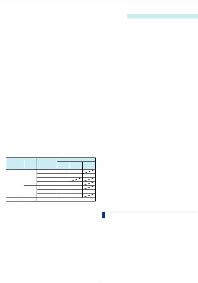
2.4 Setting Commands
|
p7 |
Output (Off) |
|
|
|
|
p2 Alarm number (1 to 4) |
||
Output Alarms |
|
|
|
|
p3 |
Hysteresis |
|
||
Syntax |
SAlarmIO,p1,p2,p3,p4,p5,p6,p7,p8 |
|
|
|
|
Alarm Type |
Hysteresis Range |
||
|
p1 |
Channel number |
|
|
|
|
H, L, DH, DL |
0.0% to 5.0% of the span |
|
|
p2 |
Alarm number (1 to 4) |
|
|
|
|
|
or scale width |
|
|
p3 |
Alarm on or off (On) |
|
Query |
SAlmHysIO[,p1[,p2]]? |
||||
|
P4 |
Alarm type (H, L, DH, DL, RH, RL, TH, TL) |
|
Example Set a 0.5% hysteresis on alarm 3 of channel |
|||||
|
|
|
|
0002. |
|
||||
|
p5 |
Value |
|
|
|
|
|
||
|
|
|
|
|
SAlmHysIO,0002,3,5 |
||||
|
p6 |
Detection (Off, On) |
|
|
|
||||
|
|
Description |
|
|
|||||
|
p7 |
Output |
|
|
• Hysteresis specified for delay high and low limit |
||||
|
|
DO |
Output to a relay (DO |
|
|
alarms (TH and TL) and high and low limits on rate-of- |
|||
|
|
|
channel) |
|
|
change alarms (RH and RL) do not apply. |
|||
|
p8 |
SW |
Outputtoaninternalswitch |
|
|
|
|
|
|
|
|
|
|
|
|
|
|||
|
Number |
|
|
|
|
|
|
|
|
|
|
|
|
SAlmDlyIO |
|
||||
|
|
If p7=DO |
Relay (DO channel) |
|
|
|
|||
|
|
|
|
|
|||||
|
|
|
number |
Alarm Delay Time |
|
||||
|
|
If p7=SW |
Internal switch number |
|
|||||
|
|
|
(001 to 100) |
Sets the alarm delay time for an AI or DI channel. |
|||||
Query |
|
|
|
Syntax |
SAlmDlyIO,p1,p2,p3,p4 |
||||
SAlarmIO[,p1[,p2]]? |
|
||||||||
Example Set a high limit alarm (H) on alarm number 2 of |
|
|
|
p1 |
Channel number |
||||
|
channel 0001. Set the alarm value to 1.8000V. |
|
|
|
p2 Hour (0 to 24) |
|
|||
|
Use the alarm detection function. When an |
|
|
|
p3 Minute (0 to 59) |
||||
|
alarm occurs, output to the relay (DO channel) |
|
|
|
P4 Second (0 to 59) |
||||
|
at number 0205. |
|
|
Query |
SAlmDlyIO[,p1]? |
||||
|
SAlarmIO,0001,2,On,H,18000,On,DO, |
|
Example Set the channel 0001 alarm delay time to 2 |
||||||
|
0205 |
|
|
|
|
minutes 30 seconds. |
|||
Description |
|
|
|
|
|
SAlmDlyIO,0001,0,2,30 |
|||
• You cannot set this on a “Skip” channel. |
|
Description |
|
|
|||||
• If p3=Off, you cannot set p4 or subsequent |
|
• Set the delay time so that it is an integer multiple of |
|||||||
parameters. |
|
|
|
the scan interval (SScan command). |
|||||
• If p7=Off, you cannot set p8. |
|
|
|
|
|
|
|||
• For the alarm values of p5, use the values in the |
|
|
|
|
|
|
|||
|
|
STagIO |
|
|
|||||
following table. |
|
|
|
|
|
||||
Channel |
Input |
Calculation |
Alarm Type |
|
Tag |
|
|
||
Type |
|
Type |
Type |
H, L, |
RH, RL DH, DL |
|
|
||
AI channel |
Volt, |
Off |
TH, TL |
|
|
Sets a tag to an AI, DI, or DO channel. |
|||
(1) |
(3) |
|
Syntax |
STagIO,p1,p2,p3 |
|||||
|
|
GS, |
Delta |
(1) |
(3) |
(5) |
|
p1 |
Channel number |
|
|
TC, |
Scale |
(2) |
|
|
|
p2 |
Tag (up to 32 characters, UTF-8) |
|
|
RTD |
Sqrt |
(2) |
(4) |
|
|
||
|
|
DI |
Off |
0, 1 |
1 |
|
|
p3 |
Tag number (up to 16 characters, ASCII) |
|
|
|
Delta |
(1) |
(3) |
(5) |
Query |
STagIO[,p1]? |
|
|
|
DI |
Scale |
(2) |
(4) |
|
Example Set the channel 0001 tag to “SYSTEM1” and |
||
DI channel |
Same as the DI input of AI channels |
|
the tag number to “TI002.” |
||||||
(1) |
Within the measurement range |
|
|
|
STagIO,0001,’SYSTEM1’,’TI002’ |
||||
(2)–5% to 105% of the scale but within –999999 to
999999 excluding the decimal point
(3) |
1 digit to (measurement upper limit – measurement |
|
SColorIO |
|||
|
|
lower limit) |
Channel Color |
|||
(4) |
1 digit to (scale upper limit – scale lower limit) but |
|||||
|
|
within 1 to 999999 excluding the decimal point |
Sets the color an AI, DI, or DO channel. |
|||
(5) |
Within the difference measurement range |
|||||
|
Syntax |
SColorIO,p1,p2,p3,p4 |
||||
• You cannot set DO channels or internal switches |
|
|||||
|
whose output type is set to Manual as output |
|
|
p1 Channel number |
||
|
destination numbers. |
|
|
p2 R value of RGB display colors (0 to 255, |
||
|
|
|
|
|
see “Description.”) |
|
|
|
|
|
|
||
|
|
|
|
|
p3 G value of RGB display colors (0 to 255, |
|
|
SAlmHysIO |
|
|
see “Description.”) |
||
Alarm Hysteresis |
|
|
P4 B value of RGB display colors (0 to 255, |
|||
|
|
see “Description.”) |
||||
Sets the alarm hysteresis for AI and DI channels. |
|
Query |
SColorIO[,p1]? |
|||
Syntax |
SAlmHysIO,p1,p2,p3 |
|
Example Set the channel 0001 display color to red. |
|||
|
|
SColorIO,0001,255,0,0 |
||||
|
|
p1 Channel number |
|
|
||
|
|
|
|
|
|
|
2-16 |
|
|
|
IM 04L51B01-17EN |
||
Loading...