


 Loading...
User’s
Manual YTA Series
Temperature Transmitters (Hardware)
[Style: S3]
IM 01C50B01-01E
IM 01C50B01-01E
14th Edition

YTA Series
Temperature Transmitters (Hardware)
|
|
|
IM 01C50B01-01E 14th Edition |
|
CONTENTS |
|
|
||
1. |
Preface....................................................................................................... |
|
|
1-1 |
|
|
■ Notes on the User’s Manual............................................................................. |
1-1 |
|
|
|
■ Notes on Safety and Modifications................................................................... |
1-1 |
|
|
|
■ For Safe Use of Product................................................................................... |
1-1 |
|
|
|
■ Warranty........................................................................................................... |
1-2 |
|
|
|
■ Trademarks....................................................................................................... |
1-2 |
|
|
|
■ATEX Documentation....................................................................................... |
1-3 |
|
2. |
Notes on Handling.................................................................................... |
2-1 |
||
|
2.1 |
Nameplate........................................................................................................... |
2-1 |
|
|
2.2 |
Transport............................................................................................................ |
|
2-1 |
|
2.3 |
Storage................................................................................................................ |
|
2-1 |
|
2.4 |
Choosing the Installation Location................................................................. |
2-1 |
|
|
2.5 |
Use of a Transceiver.......................................................................................... |
2-2 |
|
|
2.6 |
Insulation Resistance Test and Withstand Voltage Test............................... |
2-2 |
|
|
|
2.6.1 |
Insulation resistance test procedure.................................................. |
2-2 |
|
|
2.6.2 |
Withstand voltage test procedure....................................................... |
2-3 |
|
2.7 |
Installation of Explosion Protected Type Transmitters................................. |
2-3 |
|
|
|
2.7.1 |
CSACertification................................................................................ |
2-3 |
|
|
2.7.2 |
ATEX Certification.............................................................................. |
2-5 |
|
|
2.7.3 |
FM Certification.................................................................................. |
2-9 |
|
|
2.7.4 |
TIIS Certification............................................................................... |
2-11 |
|
|
2.7.5 |
IECEx Certification........................................................................... |
2-11 |
|
2.8 |
EMC Conformity Standards........................................................................... |
2-13 |
|
|
2.9 |
Low Voltage Directive..................................................................................... |
2-13 |
|
3. |
Part Names and Functions...................................................................... |
3-1 |
||
|
3.1 |
Part Names......................................................................................................... |
3-1 |
|
|
3.2 |
Setting the Hardware Error Burnout Change-over Switch........................... |
3-2 |
|
|
3.3 |
Built-in Indicator Display Function.................................................................. |
3-2 |
|
4. |
Installation................................................................................................. |
|
4-1 |
|
14th Edition:April 2013(KP) |
IM 01C50B01-01E |
All Rights Reserved, Copyright © 1998, Yokogawa Electric Corporation |
|

5. |
Wiring......................................................................................................... |
|
|
5-1 |
|
5.1 |
Notes on Wiring................................................................................................. |
5-1 |
|
|
5.2 |
Loop Construction............................................................................................ |
5-1 |
|
|
5.3 |
Cable Selection.................................................................................................. |
5-1 |
|
|
|
5.3.1 |
Input signal Cable Selection............................................................... |
5-1 |
|
|
5.3.2 |
Output Signal Cable Selection........................................................... |
5-2 |
|
5.4 |
Cable and Terminal Connections.................................................................... |
5-2 |
|
|
|
5.4.1 |
Input Terminal Connections................................................................ |
5-2 |
|
|
5.4.2 |
Output Terminal Connection............................................................... |
5-3 |
|
5.5 |
Wiring Cautions................................................................................................. |
5-4 |
|
|
5.6 |
Grounding.......................................................................................................... |
5-5 |
|
6. |
Maintenance.............................................................................................. |
|
6-1 |
|
|
6.1 |
General................................................................................................................ |
|
6-1 |
|
6.2 |
Calibration.......................................................................................................... |
6-1 |
|
|
|
6.2.1 |
Selection of Equipment for Calibration............................................... |
6-1 |
|
|
6.2.2 |
Calibration Procedure......................................................................... |
6-1 |
|
6.3 |
Disassembly and Assembly............................................................................. |
6-2 |
|
|
|
6.3.1 |
Replacement of Built-in Indicator....................................................... |
6-3 |
|
|
6.3.2 |
Replacement of CPUAssembly......................................................... |
6-3 |
|
6.4 |
Troubleshooting................................................................................................ |
6-4 |
|
|
|
6.4.1 |
Basic Troubleshooting Flow............................................................... |
6-4 |
|
|
6.4.2 |
Example of Troubleshooting Flow...................................................... |
6-4 |
|
6.5 |
Integral Indicator and Error Display................................................................ |
6-6 |
|
7. |
General Specifications............................................................................. |
7-1 |
||
|
7.1 |
Standard Specifications................................................................................... |
7-1 |
|
|
7.2 |
Model and Suffix Codes.................................................................................... |
7-5 |
|
|
7.3 |
Optional Specifications.................................................................................... |
7-5 |
|
|
7.4 |
Dimensions........................................................................................................ |
7-7 |
|
Installation and Operating Precautions for TIIS Flameproof Equipment
........................................................................................................... EX-B03E Customer Maintenance Parts List......................................CMPL 01C50B01-02E Revision Information
IM 01C50B01-01E

<1. Preface> |
1-1 |
1.Preface
The YTAtemperature transmitter is fully factorytested according to the specifications indicated on the order.
In order for the YTAtemperature transmitter to be fully functional and to operate in an efficient manner, the manual must be carefully read to become familiar with the functions, operation, and handling of the YTA.
This manual gives instructions on handling, wiring and maintenance of YTA110, YTA310 and YTA320 temperature transmitters. Changing the parameter settings requires a terminal dedicated to the HART protocol or the BRAIN protocol. For details on how to set the parameters of these transmitters, refer to the “BRAIN Protocol” IM 0lC50T03-01E or “HART Protocol” IM 01C50T01-01E.
For FOUNDATION Fieldbus communication type, please refer to IM 01C50T02-01E in addition to this manual.
■Notes on the User’s Manual
•This manual should be delivered to the end user.
•The information contained in this manual is subject to change without prior notice.
•The information contained in this manual, in whole or part, shall not be transcribed or copied without notice.
•In no case does this manual guarantee the merchant ability of the transmitter or its adaptability to a specific client need.
•Should any doubt or error be found in this manual, submit inquiries to your local dealer.
•No special specifications are contained in this manual.
•Changes to specifications, structure, and components used may not lead to the revision of this manual unless such changes affect the function and performance of the transmitter.
■Notes on Safety and Modifications
•Before handling the YTA, it is absolutely imperative that users of this equipment read and observe the safety instructions mentioned in each section of the manual in order to ensure the protection and safety of operators, the YTA itself and the system containing the transmitter. We are not liable for any accidents arising out of
handling that does not adhere to the guidelines established in the safety instructions.
•No maintenance should be performed on explosionproof type temperature transmitters while the equipment is energized. If maintenance is required with the cover open, always first use a gas detector to check that no explosive gases are present.
•If the user attempts to repair or modify an explosionproof type transmitter and is unable to restore it to its original condition, damage to the explosionproof features result, leading to dangerous conditions. Contact your authorized Yokogawa Electric Corporation representative for repairs or modifications of an explosionproof type transmitter.
■For Safe Use of Product
Please give your attention to the followings.
(a) Installation
•The instrument must be installed by an expert engineer or a skilled personnel. The procedures described about INSTALLATION are not permitted for operators.
•In case of high process temperature, care should be taken not to burn yourself because the surface of the case reaches a high temperature.
•All installation shall comply with local installation requirement and local electrical code.
(b) Wiring
•The instrument must be installed by an expert engineer or a skilled personnel. The procedures described about WIRING are not permitted for operators.
•Please confirm that voltages between the power supply and the instrument before connecting the power cables and that the cables are not powered before connecting.
(c) Maintenance
•Please do not carry out except being written to a maintenance descriptions. When these procedures are needed, please contact nearest YOKOGAWAoffice.
•Care should be taken to prevent the build up of drift, dust or other material on the display glass and name plate. In case of its maintenance, soft and dry cloth is used.
IM 01C50B01-01E

<1. Preface> |
1-2 |
|
|
(d) Modification
•Yokogawa will not be liable for malfunctions or damage resulting from any modification made to this instrument by the customer.
Symbols used in this manual
The YTAtemperature transmitter and this manual use the following safety related symbols and signals.
 WARNING
Contains precautions to protect against the chance of explosion or electric shock which, if not observed, could lead to death or serious injury.
 CAUTION
Contains precautions to protect against danger, which, if not observed, could lead to personal injury or damage to the instrument.
 IMPORTANT
Contains precautions to be observed to protect against adverse conditions that may lead to damage to the instrument or a system failure.
 NOTE
NOTE
Contains precautions to be observed with regard to understanding operation and functions.
Some of the diagrams in this manual are partially omitted, described in writing, or simplified for ease of explanation. The screen drawings contained in the instruction manual may have a display position or characters (upper/lower case) that differ slightly from the full-scale screen to an extent that does not hinder the understanding of functions or monitoring of operation.
■Warranty
•The warranty period of the instrument is written on the estimate sheet that is included with your purchase.Any trouble arising during the warranty period shall be repaired free of charge.
•Inquiries with regard to problems with the instrument shall be accepted by the sales outlet or our local dealer representative.
•Should the instrument be found to be defective, inform us of the model name and the serial number of the instrument together with a detailed description of nonconformance and a progress report. Outline drawings or related data will also be helpful for repair.
•Whether or not the defective instrument is repaired free of charge depends on the result of our inspection.
Conditions not eligible for chargeexempt repair.
•Problems caused by improper or insufficient maintenance on the part of the customer.
•Trouble or damage caused by mishandling, misusage, or storage that exceeds the design or specification requirements.
•Problems caused by improper installation location or by maintenance conducted in a nonconforming location.
•Trouble or damage was caused by modification or repair that was handled by a party or parties other than our consigned agent.
•Trouble or damage was caused by inappropriate relocation following delivery.
•Trouble or damage was caused by fire, earthquake, wind or flood damage, lightning strikes or other acts of God that are not directly a result of problems with this instrument.
■Trademarks
•HART is a trademark of the HART Communication Foundation.
•Registered trademarks or trademarks appearing in this manual are not designated by a TM or ® symbol.
•Other company names and product names used in this manual are the registered trademarks or trademarks of their respective owners.
IM 01C50B01-01E

<1. Preface> |
1-3 |
|
|
■ATEX Documentation
This procedure is only applicable to the countries in European Union.
GB |
SK |
CZ
DK
I |
LT |
E |
LV |
EST
NL
PL
SF
SLO
P
H
F
BG
D
RO
S
M
GR
IM 01C50B01-01E
<2. Notes on Handling> |
2-1 |
|
|
2.Notes on Handling
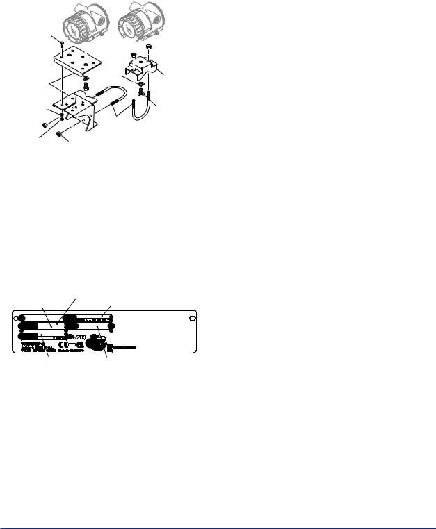
The YTAtemperature transmitter is fully factorytested upon shipment. When the YTAis delivered, check the appearance for damage, and also check that the transmitter mounting parts shown in Figure 2.1 are included with your shipment. If “No Mounting Bracket” is indicated, no transmitter mounting bracket is included.
Bracket fastening bolt


 U-bolt nut
Vertical pipe |
Spring |
Horizontal |
|
washer |
pipe mounting |
||
mounting |
|||
|
bracket |
||
bracket |
|
||
|
|
||
Spring |
|
Transmitter |
|
washer |
U-bolt |
fastening bolt |
|
|
|||
|
|
||
Bracket |
U-bolt nut |
|
|
fastening nut |
|
||
|
|
||
|
|
F0201.ai |
Figure 2.1 Transmitter mounting parts
2.1Nameplate
The model name and configuration are indicated on the nameplate. Verify that the configuration indicated in the “Model and Suffix Code” in Chapter 7 is in compliance with the specifications written on the order sheet.
Specification code |
Model name |
Serial No. |
2.3Storage
When an extended storage period is expected, observe the following precautions:
1.If at all possible, store the transmitter in factoryshipped condition, that is, in the original shipping container.
2.Choose a storage location that satisfies the following requirements.
•Alocation that is not exposed to rain or water.
•Alocation subject to a minimum of vibration or impact.
•The following temperature and humidity range is recommended. Ordinary temperature and humidity (25°C, 65%) are preferable.
Temperature:
No Integral indicator –40 to 85°C With Integral indicator –30 to 80°C
Humidity: 5 to 100% RH (at 40°C)
3.The performance of the transmitter may be impaired if stored in an area exposed to direct rain and water. To avoid damage to the transmitter, install it immediately after
removal from shipping container. Follow wiring instructions in Chapter 5.
2.4Choosing the Installation Location
Although the temperature transmitter is designed to operate in a vigorous environment, to maintain stability and accuracy, the following is recommended:
TEMPERATURE |
NO. |
|
TRANSMITTER |
OUTPUT |
|
MODEL |
YTA |
CAL |
SUFFIX |
|
RNG |
STYLE
SUPPLY
|
|
|
|
|
|
|
|
|
|
|
|
|
|
|
|
|
|
|
|
|
|
Style code |
|
Factory-shipped range and unit |
||
|
|
|
|
|
|
|
F0202.ai |
|
Figure 2.2 Name plate
2.2Transport
To prevent damage while in transit, leave the transmitter in the original shipping container until it reaches the installation site.
(1) Ambient Temperature
It is preferable to not to expose the instrument to extreme temperatures or temperature fluctuations. If the instrument is exposed to radiation heat
a thermal protection system and appropriate ventilation is recommended.
(2) Environmental Requirements
Do not allow the instrument to be installed in a location that is exposed to corrosive atmospheric conditions. When using the instrument in a corrosive environment, ensure the location is well ventilated.
The unit and its wiring should be protected from exposure to rainwater.
IM 01C50B01-01E

<2. Notes on Handling> |
2-2 |
|
|
(3) Impact and Vibration
It is recommended that the instrument be installed in a location that is subject to a minimum amount of impact and vibration.
2.5Use of a Transceiver
Although the temperature transmitter is designed to resist influence from high frequency noise; use of a transceiver in the vicinity of installation may cause problems. Installing the transmitter in an area free from high frequency noise (RFI) is recommended.
2.6Insulation Resistance Test and Withstand Voltage Test
 CAUTION
(1)Overvoltage of the test voltage that is so small that it does not cause an dielectric breakdown may in fact deteriorate insulation and lower the safety performance; to prevent this it is recommended that the amount of testing be kept to a minimum.
(2)The voltage for the insulation resistance test must be 500 VAC or lower, and the voltage for the withstand voltage test must be 500 VAC or lower. Failure to heed these guidelines may cause faulty operation.
(3)Where a built-in arrester is provided (suffix code: /A), the voltage for the insulation resistance test must be 100 VDC or lower, and the voltage for the withstand voltage test must be 100 VAC or lower. Failure to heed these guidelines may cause faulty operation.
Follow the steps below to perform the test, the wiring of the transmission line must be removed before initiating testing.
2.6.1 Insulation resistance test procedure
Testing between the output terminal and input terminal
1.Lay transition wiring between the + terminal, the – terminal, and the check terminal of the terminal box.
2.Lay wiring across terminals 1, 2, 3, and 4 of the terminal box.
3.Connect the insulation resistance meter (with the power turned OFF) between the transition wiring of Steps 1 and 2 above. The polarity of
the input terminals must be positive and that of the output terminals must be negative.
4.Turn the power of the insulation resistance meter ON and measure the insulation resistance. The duration of the applied voltage must be the period during which 100MΩ
or more is confirmed (or 20MΩ if the unit is equipped with a built-in arrester).
5.Upon completion of the test, remove the insulation resistance meter, connect a 100KΩ resistor between the transition wiring, and allow the electricity to discharge. Do not touch the terminal with your bare hands while the electricity is discharging for more than 1 second.
Testing between the output terminal and grounding terminal
1.Lay transition wiring between the + terminal, the - terminal, and the check terminal of the terminal box, then connect an insulation resistance meter (with the power turned OFF) between the transition wiring and the grounding terminal. The polarity of the transition wiring must be positive and that of the grounding terminal must be negative.
2.Turn the power of the insulation resistance meter ON and measure the insulation resistance. The duration of the applied voltage must be the period during which 100MΩ
or more is confirmed (or 20MΩ if the unit is equipped with a built-in arrester).
3.Upon completion of the test, remove the insulation resistance meter, connect a 100KΩ resistor between the transition wiring and the grounding terminal, and allow the electricity to discharge. Do not touch the terminal with your bare hands while the electricity is discharging for more than 1 second.
Testing between the input terminal and grounding terminal
1.Lay transition wiring between terminals 1, 2, 3, 4 and 5 of the terminal box, and connect the insulation resistor (with the power turned OFF) between the transition wiring and the grounding terminal. The polarity of the transition wiring must be positive and that of the grounding terminal must be negative.
2.Turn the power of the insulation resistance meter ON and measure the insulation resistance. The duration of the applied voltage must be the period during which 100MΩ
IM 01C50B01-01E

<2. Notes on Handling> |
2-3 |
|
|
or more is confirmed (or 20MΩ if the unit is equipped with a built-in arrester).
3.Upon completion of the test, remove the insulation resistance meter, connect a 100KΩ resistor between the transition wiring and the grounding terminal, and allow the electricity to discharge. Do not touch the terminal with your bare hands while the electricity is discharging for more than 1 second.
2.6.2 Withstand voltage test procedure
Testing between the output terminal and the input terminal
1.Lay transition wiring between the + terminal, the – terminal, and the check terminal of the terminal box.
2.Lay transition wiring between terminals 1, 2, 3, 4 and 5 of the terminal box.
3.Connect the withstand voltage tester (with the power turned OFF) between the transition wiring shown in Steps 1 and 2 above.
4.After setting the current limit value of the withstand voltage tester to 10mA, turn the power ON, and carefully increase the impressed voltage from 0V to the specified value.
5.The voltage at the specified value must remain for a duration of one minute.
6.Upon completion of the test, carefully reduce the voltage so that no voltage surge occurs.
Testing between the output terminal and the grounding terminal
1.Lay the transition wiring between the + terminal, the - terminal and the check terminal of the terminal box, and connect the withstand voltage tester (with the power turned OFF) between the transition wiring and the grounding terminal. Connect the grounding side of the withstand voltage tester to the grounding terminal.
2.After setting the current limit value of the withstand voltage tester to 10mA, turn the power ON, and gradually increase the impressed voltage from 0V to the specified value.
3.The voltage at the specified value must remain for a duration of one minute.
4.Upon completion of the test, carefully reduce the voltage so that no voltage surge occurs.
Testing between the input terminal and the grounding terminal
1. Lay the transition wiring across terminals 1, 2,
3, 4, and 5 of the terminal box and connect the withstand voltage tester (with the power turned OFF) between the transition wiring and the grounding terminal. Connect the grounding side of the withstand voltage tester to the grounding terminal.
2.After setting the current limit value of the withstand voltage tester to 10mA, turn the power ON, and gradually increase the impressed voltage from 0V to the specified value.
3.The voltage at the specified value must remain for a duration of one minute.
4.Upon completion of the test, carefully reduce the voltage so that no voltage surge occurs.
2.7Installation of Explosion Protected Type Transmitters
In this section, further requirements and differences and for explosionproof type instrument are described. For explosionproof type instrument, the description in this chapter is prior to other description in this users manual.
 CAUTION
To preserve the safety of explosionproof equipment requires great care during mounting, wiring, and piping. Safety requirements also place restrictions on maintenance and repair activities. Please read the following sections very carefully.
2.7.1 CSACertification
Model YTA110/CU1, YTA310/CU1 and YTA320/ CU1 temperature transmitters can be selected the type of protection (CSAIntrinsically Safe, Nonincendive, or Explosionproof) for use in hazardous locations.
Note 1. For the installation of this transmitter, once a particular type of protection is selected, any other type of protection cannot be used. The installation must be in accordance with the description about the type of protection in this instruction manual.
Note 2. In order to avoid confusion, unnecessary marking is crossed out on the label other than the selected type of protection when the transmitter is installed.
IM 01C50B01-01E
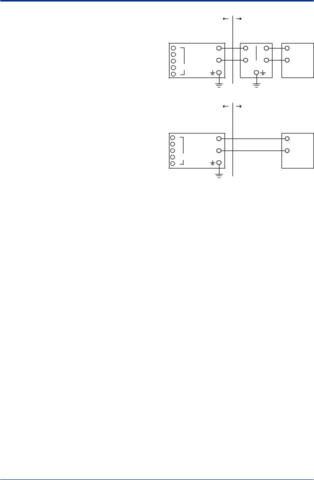
a)CSA Intrinsically Safe Type/Non-incendive Type
Caution for CSAIntrinsically safe type. (Following contents refers “DOC No. ICS008-A13 P.1-1 and P.1- 2”)
Note 1. Model YTA110/CU1, YTA310/CU1 and YTA320/CU1 temperature transmitters are applicable for use in hazardous locations:
Certificate 172608-0001053837 [For CSAC22.2]
•Applicable Standard: C22.2 No.0, C22.2 No.0.4, C22.2 No.25, C22.2 No.94,
C22.2 No.142, C22.2 No.157, C22.2 No.213
•Intrinsically Safe for Class I, II, III, Division 1, GroupsA, B, C, D, E, F & G.
•Non-incendive for Class I, II, Division 2, Groups A, B, C, D, F & G, Class III, Division 1.
•Encl. “Type 4X”
•Temperature Class: T4
•Ambient temperature: –40 to 60°C
Note 2. Entity Parameters (Electrical/Nonincendive
field wiring parameters)
•[Supply Circuit]
Vmax = 30 V, Imax = 165 mA, Pmax = 0.9 W, Ci = 18 nF, Li = 730 μH
•[Associated apparatus]
Voc ≤ 30 V, Isc ≤ 165 mA, Pmax ≤ 0.9 W
•[Sensor Circuit]
Voc = 9 V, Isc = 40 mA, Po = 90 mW, Ca = 1 μF, La = 10 mH
Note 3. Installation
•All wiring shall comply with Canadian Electrical Code Part I and Local Electrical Codes.
•For the sensor circuitry, the above parameters for sensor circuit must be taken into account.
•Dust-tight conduit seal must be used when installed in class II and III environments.
•In any used safety barrier, output current must be limited by a resistor 'R' such that Isc=Voc/R.
•The safety barrier must be CSAcertified, and the input voltage of the barrier must be less than 250Vrms/Vdc.
•For non-incendive type, general purpose equipment must be CSAcertified and the equipment which have non-incendive field wiring parameters.
•The instrument modification or parts replacement by other than authorized representative of Yokogawa Electric Corporation is prohibited and will void Canadian Standards Intrinsically safe and nonincendive Certification.
|
<2. Notes on Handling> |
2-4 |
||
|
[Intrinsically Safe] |
|
|
|
Hazardous Location |
Nonhazardous Location |
|||
|
YTA Series |
|
|
General |
|
Temperature |
Safety Barrier |
Purpose |
|
|
Transmitter |
Equipment |
||
1 |
+ |
+ |
+ |
+ |
2 |
Supply |
|
|
|
3 |
– |
– |
– |
– |
4 |
Sensor |
|
|
|
5 |
|
|
|
|
|
[Non-incendive] |
|
|
|
Hazardous Location |
Nonhazardous Location |
|||
|
YTA Series |
|
|
General |
|
Temperature |
|
|
Purpose |
|
Transmitter |
|
|
Equipment |
1 |
+ |
|
|
+ |
2 |
Supply |
|
|
|
3 |
– |
|
|
– |
4 |
Sensor |
Not Use |
|
|
5 |
|
Safety Barrier |
|
|
|
|
|
|
F0203.ai |
b)CSA Explosionproof Type
Caution for CSAExplosionproof type
Note 1. Model YTA110/CU1, YTA310/CU1 and YTA320/CU1 temperature transmitters are applicable for use in hazardous locations:
Certificate 1089576 [For CSAC22.2]
•Applicable Standard: C22.2 No.0,
C22.2 No.0.4, C22.2 No.25, C22.2 No.30,
C22.2 No.94, C22.2 No.142, C22.2 No.157,
C22.2 No.213, C22.2 No.1010.1
•Explosionproof for Class I, Division 1, Groups B, C and D.
•Dust-ignitionproof for Class II, Groups E, F and G, Class III.
•Encl “Type 4X”
•Temperature Class: T6
•Ambient Temperature: –40 to 60°C
•Supply Voltage: 42 V dc max.
•Output Signal: 4 to 20 mA
Note 2. Wiring
•All wiring shall comply with Canadian Electrical Code Part I and Local Electrical Codes.
•In hazardous location, wiring shall be in conduit as shown in the figure.
WARNING: ASEALSHALLBE INSTALLED WITHIN 50 cm OF THE ENCLOSURE. UN SCELLEMENT DOIT ÊTRE INSTALLÉ À MOINS
DE 50 cm DU BOÎTIER.
IM 01C50B01-01E
<2. Notes on Handling> |
2-5 |
|
|
•When installed in Division 2, “FACTORY SEALED, CONDUIT SEALNOT REQUIRED”.
Note 3. Operation
•Keep strictly the “WARNING” on the label attached on the transmitter.
WARNING: OPEN CIRCUIT BEFORE REMOVING COVER. OUVRIR LE CIRCUITAVANT D´ENLEVER LE COUVERCLE.
•Take care not to generate mechanical spark when access to the instrument and peripheral devices in hazardous location.
Note 4. Maintenance and Repair
•The instrument modification or parts replacement by other than authorized representative of Yokogawa Electric Corporation is prohibited and will void Canadian Standards Explosionproof Certification.
2.7.2 ATEX Certification
Model YTA110/KU2, YTA310/KU2 and YTA320/ KU2 temperature transmitters can be selected the type of protection (ATEX Intrinsically Safe “ia” or ATEX Flameproof orATEX Intrinsically Safe “ic”) for use in hazardous locations.
Note 1. For the installation of this transmitter, once a particular type of protection is selected, any other type of protection cannot be used. The installation must be in accordance with the description about the type of protection in this instruction manual.
Note 2. In order to avoid confusion, unnecessary marking is crossed out on the label other than the selected type of protection when the transmitter is installed.
|
Hazardous Locations Division 1 |
||
50 cm Max. |
YTA Series |
50 cm Max. |
|
Sensor |
|
|
|
Sealing Fitting |
|
Conduit |
Sealing Fitting |
|
|
||
Certified/Listed Temperature Sensor
Explosionproof Class I, Groups C and D Dustignitionproof Class II, Groups E, F and G, Class III
Wiring method shall be suitable for the specified hazardous locations.
Non-hazardous Locations
Non-hazardous
Location
Equipment
42 V DC Max.
4 to 20 mA DC Signal
Hazardous Locations Division 2
YTA Series
Sensor
Conduit |
Sealing Fitting |
Certified/Listed Temperature Sensor
Explosionproof Class I, Groups C and D
Dustignitionproof Class II, Groups E, F and G, Class III
Wiring method shall be suitable for the specified hazardous locations.
Non-hazardous Locations
Non-hazardous
Location
Equipment
42 V DC Max.
4 to 20 mA DC Signal
F0204.ai
IM 01C50B01-01E
(1) Technical Data
a)ATEX Intrinsically Safe “ia”
Caution forATEX Intrinsically safe “ia”
Note 1. Model YTA110/KU2, YTA310/KU2 and YTA320/KU2 temperature transmitters for potentially explosive atmospheres:
•No. KEMA02ATEX1026X
•Applicable Standard: EN 60079-0:2009, EN 60079-11:2007, EN 60079-26:2007, EN 60529:1991
•Type of Protection and Marking code: II 1 G Ex ia IIC T4...T5
•Temperature Class: T5, T4
•Ambient Temperature: –40 to 70°C for T4, –40 to 50°C for T5
•Enclosure: IP67
Note 2. Electrical Data
•In type of explosion protection intrinsic safety II 1 G Ex ia IIC only for connection to a certified intrinsically safe circuit with following maximum values:
•[Supply circuit]
Ui = 30 V |
Ii = 165 mA |
Pi = 900 mW |
|
Effective internal capacitance, Ci = 20 nF |
|
Effective internal inductance, Li = 730 μH |
|
• [Sensor circuit] |
|
Uo = 9 V |
Io = 40 mA |
Po = 90 mW |
|
Max. allowed external capacitance, Co = 0.7μF
Max. allowed external inductance, Lo = 10 mH
•The above parameters apply when one of the two conditions below is given:
-the total Li of the external circuit (excluding the cable) is < 1% of the Lo value or
-the total Ci of the external circuit (excluding the cable) is < 1% of the Co value.
•The above parameters are reduced to 50% when both of the two conditions below are given:
-the total Li of the external circuit (excluding the cable) is ≥ 1% of the Lo value and
-the total Ci of the external circuit (excluding the cable) is ≥ 1% of the Co value.
•The reduced capacitance of the external circuit (including cable) shall not be greater than 1μF for Group IIB and 600nF for Group IIC.
Note 3. Installation
•All wiring shall comply with local installation requirements. (Refer to the installation diagram)
Note 4. Operation
<2. Notes on Handling> |
2-6 |
•Keep strictly the “WARNING” on the label on the transmitter.
WARNING: POTENTIALELECTROSTATIC CHARGING HAZARD. SEE USER’S MANUALBEFORE USE.
Note 5. Maintenance and Repair
•The instrument modification or parts replacement by other than authorized representative of Yokogawa Electric Corporation is prohibited and will voidATEX Intrinsically safe “ia” Certification.
Note 6. Specific condition of use
•Because the enclosure of the Temperature Transmitter is made of aluminium, if it is mounted in an area where the use of category 1G apparatus is required, it must be installed such, that, even in the event of rare incidents, ignition source due to impact and friction sparks are excluded.
•Avoid any actions that cause the generation of electrostatic charge on the non-metallic parts, such as rubbing with a dry cloth on coating face
of product.
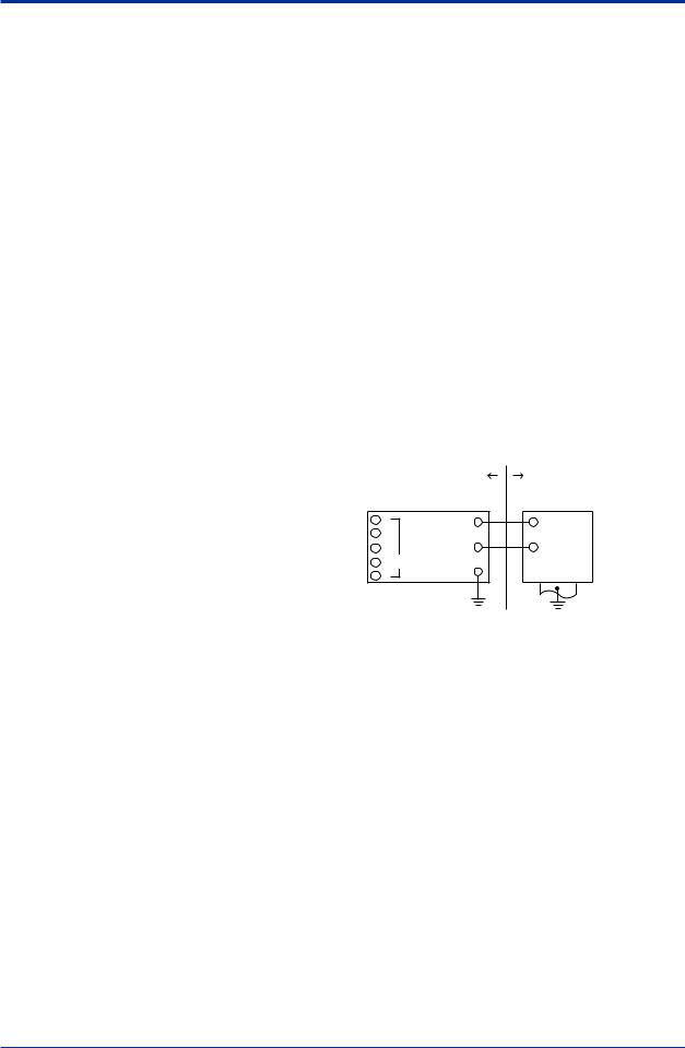
[Installation Diagram]
Hazardous Location |
Nonhazardous Location |
|
|
Transmitter |
Safety Barrier *1 |
1 |
+ |
+ |
2 |
Supply |
|
3 |
– |
– |
4 |
Sensor |
|
5 |
|
|
|
|
F0205.ai |
*1: In any safety barriers used the output current must be limited by a resistor “R” such that Imaxout-Uz/R.
b)ATEX Flameproof Type and Dust Ignition Proof Type
Caution forATEX Flameproof Type and Dust Ignition Proof Type
Note 1. Model YTA110/KU2, YTA310/KU2 and YTA320/KU2 temperature transmitters are applicable for use in hazardous locations:
•No. KEMA07ATEX0130
•Applicable Standard: EN 60079-0:2006, IEC 60079-1:2007, EN 61241-0:2006, EN 61241-1:2004
•Type of Protection and Marking Code: II 2 G Ex d IIC T6/T5, II 2 D Ex tDA21 IP67 T70°C, T90°C
•Ambient Temperature for GasAtmospheres:
–40 to 75°C (T6), –40 to 80°C (T5)
IM 01C50B01-01E

<2. Notes on Handling> |
2-7 |
|
|
•Ambient Temperature for Dust Atmospheres: –40 to 65°C (T70°C), –40 to 80°C (T90°C)
•Enclosure: IP67
Note 2. Electrical Data
•Supply voltage: 42 V dc max.
•Output signal: 4 to 20 mA Note 3. Installation
•All wiring shall comply with local installation requirement.
•The cable entry devices shall be of a certified flameproof type, suitable for the conditions of use.
Note 4. Operation
•Keep strictly the “WARNING” on the label on the transmitter.
WARNING: AFTER DE-ENERGIZING, DELAY 5 MINUTES BEFORE OPENING.
WHEN THEAMBIENTTEMP. ≥
70°C, USE THE HEATRESISTING CABLES OF HIGHER THAN 90°C.
•Take care not to generate mechanical spark when access to the instrument and peripheral devices in hazardous location.
Note 5. Maintenance and Repair
•The instrument modification or parts replacement by other than authorized representative of Yokogawa Electric Corporation is prohibited and will void ATEX
Flameproof Certification.
c)ATEX Intrinsically Safe “ic”
 WARNING
When using a power supply not having a nonincendive circuit, please pay attention not to ignite in the surrounding flammable atmosphere.
In such a case, we recommend using wiring metal conduit in order to prevent the ignition.
Caution for ATEX Intrinsically Safe “ic”
Note 1. Model YTA110/KU2, YTA310/KU2 and YTA320/KU2 temperature transmitters for potentially explosive atmospheres:
•Applicable standard: EN 60079-0:2009, EN 60079-0:2012, EN 60079-11:2012
•Type of Protection and Marking: 


 II 3 G Ex ic IIC T5…T4 Gc
•Ambient Temperature: –30 to 50°C for T5, –30 to 70°C for T4
•IP Code: IP67
•Overvoltage Category: I
Note 2. Electrical Data
•[Supply circuit] Ui = 30 V
Effective internal capacitance, Ci = 28 nF
Effective internal inductance, Li = 730 μH
•[Sensor circuit]
Uo= 9 V Io = 40 mA Po = 90 mW
Max. allowed external capacitance, Co = 0.7 μF
Max. allowed external inductance, Lo = 10 mH
•The above parameters apply when one of the two conditions below is given:
-the total Li of the external circuit (excluding the cable) is < 1% of the Lo value or
-the total Ci of the external circuit (excluding the cable) is < 1% of the Co value.
•The above parameters are reduced to 50% when both of the two conditions below are given:
-the total Li of the external circuit (excluding the cable) is ≥ 1% of the Lo value and
-the total Ci of the external circuit (excluding the cable) is ≥ 1% of the Co value.
•The reduced capacitance of the external circuit
(including cable) shall not be greater than 1μF for Group IIB and 600nF for Group IIC.
Note 3. Installation
•All wiring shall comply with local installation requirements. (refer to the installation diagram)
•Cable glands, adapters and/or blanking elements shall be of Ex “n”, Ex “e” or Ex “d” and shall be installed so as to maintain the specified degree of protection (IP code) of the equipment.
Note 4. Operation
•Keep strictly the “WARNING” on the label on the transmitter.
WARNING: POTENTIAL ELECTROSTATIC CHARGING HAZARD - SEE USER’S MANUAL
Note 5. Maintenance and Repair
•The instrument modification or parts replacement by other than authorized
representative of Yokogawa Electric Corporation is prohibited and will void ATEX Intrinsically Safe “ic“.
Note 6. Specific Conditions of Use
•Precautions shall be taken to minimize the risk from electrostatic discharge of painted parts.
•The dielectric strength of at least 500 V a.c. r.m.s between the intrinsically safe circuits and the enclosure of the Model YTA series temperature transmitter is limited only by the overvoltage protection.
IM 01C50B01-01E
<2. Notes on Handling> |
2-8 |
|
|
|
Hazardous Area |
|
|
|
Non-hazardous Area |
||
|
|
|
|
||||
|
|
|
|
|
|
|
|
Temperature Transmitter |
|
|
|
|
Associated Apparatus |
||
1 |
SUPPLY + |
|
|
|
|
|
+ |
2 |
|
|
|
||||
|
|
|
|||||
3 |
SENSOR |
|
|
|
|
|
|
4 |
SUPPLY – |
|
|
|
|
|
– |
|
|
|
|
|
|||
|
|
|
|
|
|
|
|
5 |
C |
|
|
|
|
|
|
|
|
|
|
|
|
|
|
Electrical data are as follows; |
|
|
|
|
|
||
Supply Input (Terminals: + and -) |
|
Sensor Output (Terminals: 1 to 5) |
|||||
|
Ui = 30 V |
|
|
Uo = 9 V |
|||
|
Ci = 28 nF |
|
|
Io = 40 mA |
|||
|
Li = 730 μH |
|
|
Po = 90 mW |
|||
|
|
|
|
|
Co = 0.7 μF |
||
|
|
|
|
|
Lo = 10 mH |
||
|
|
|
|
|
|
|
F0206.ai |
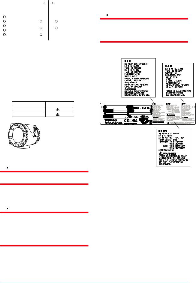
(2) Electrical Connection
The type of electrical connection is stamped near the electrical connection port according to the following marking.
Screw Size |
Marking |
ISO M20×1.5 female |
M |
ANSI 1/2 NPT female |
A |
T0201.ai
 Location of the marking
F0207.ai
(3)Installation
 WARNING
All wiring shall comply with local installation requirement and local electrical code.
(4) Operation
 WARNING
•OPEN CIRCUIT BEFORE REMOVING COVER. INSTALL IN ACCORDANCE WITH THIS USER’S MANUAL
•Take care not to generate mechanical sparking when access to the instrument and peripheral devices in hazardous locations.
(5) Maintenance and Repair
 WARNING
The instrument modification or parts replacement by other than authorized Representative of Yokogawa Electric Corporation is prohibited and will void the certification.
(6) Name Plate
TEMPERATURE |
NO. |
|
TRANSMITTER |
OUTPUT |
|
MODEL |
YTA |
CAL |
SUFFIX |
|
RNG |
STYLE
SUPPLY 
 *3
*3
F0208.ai |
MODEL: Specified model code.
SUFFIX: Specified suffix code.
STYLE: Style code. SUPPLY: Supply voltage.
NO.: Serial number and year of production*1. OUTPUT: Output signal.
FACTORY CAL: Specified calibration range.


 TOKYO 180-8750 JAPAN: The manufacturer name and the address*2.
*1: The third figure from the left shows the production year.
The relationship between the production year and the third figure is shown below.
The third figure |
F |
G |
H |
J |
K |
L |
M |
|
The year of |
2006 |
2007 |
2008 |
2009 |
2010 |
2011 |
2012 |
|
Production |
||||||||
|
|
|
|
|
|
|
IM 01C50B01-01E

<2. Notes on Handling> |
2-9 |
|
|
For example, the production year of the product engraved in “NO.” column on the name plate as follows is 2006.
C2F616294
The year 2006
*2: “180-8750” is a postal code which represents the following address.
2-9-32 Nakacho, Musashino-shi, Tokyo Japan
*3: The identification number of Notified Body
2.7.3 FM Certification
a)FM Intrinsically Safe Type
Caution for FM Intrinsically safe type.
Note 1. Model YTA/FU1 temperature transmitter is
applicable for use in hazardous locations.
•Applicable Standard: FM 3600, FM 3610, FM 3611, FM 3810, NEMA-250
•Intrinsically Safe for Class I, Division 1, Groups A, B, C & D.
Class II, Division 1, Groups E, F & G and Class III, Division 1 Hazardous Locations.
•Outdoor hazardous locations, NEMA4X.
•Temperature Class: T4
•Ambient temperature: –40 to 60°C
Note 2. Entity Parameters of the temperature
transmitter: |
|
• Supply Circuit (+ and –) |
• Sensor Circuit (1 to 5) |
Vmax : 30 V |
Voc/Vt : 9 V |
Imax : 165 mA |
Isc/It : 40 mA |
Pmax : 0.9 W |
Po : 0.09 W |
Ci : 18 nF |
Ca : 1 μF |
Li : 730 μH |
La : 10 mH |
•For the sensor input circuitry, these entity parameters must be taken into account when installed.
•Installation Requirements between temperature transmitter and safety barrier:
Voc ≤ Vmax, Isc ≤ Imax, Ca ≥ Ci + Ccable, La ≥ Li + Lcable
Voc, Isc, Ca and La are parameters of the safety barrier.
Note 3. Installation
•The safety barrier must be FM approved.
•Input voltage of the safety barrier must be less than 250 Vrms/Vdc.
•Installation should be in accordance withANSI/ ISARP12.6 “Installation of Intrinsically Safe Systems for Hazardous (Classified) Locations” and the National Electric Code (ANSI/NFPA 70).
•Intrinsically safe sensor must be FMRC Approved or be simple apparatus (a device which will neither generate nor store more than 1.2 V, 0.1A, 25 mW or 20 μJ, ex. switches, thermocouples, LED’s or RTD’s).
•Dust-tight conduit seal must be used when installed in a Class II and III environments.
Note 4. Maintenance and Repair
•The instrument modification or parts replacement by other than authorized representative of Yokogawa Electric Corporation is prohibited and will void Factory Mutual Intrinsically safe and Nonincendive Approval.
|
|
[Intrinsically Safe] |
|
|
|
Hazardous |
Nonhazardous |
||
|
Location |
|
Location |
|
|
|
|
General |
|
|
|
|
Purpose |
|
Class I, II, III, Division 1, |
|
Equipment |
||
|
|
|
||
Groups A, B, C, D, E, F and G |
|
|
||
|
|
|
+ |
– |
Intrinsically |
|
|
|
|
Safe Sensor |
|
|
|
|
or Simple |
Temperature |
|
|
|
Apparatus |
Transmitter |
|
Safety Barrier |
|
1 |
Supply |
+ |
+ |
+ |
2 |
|
|
– |
|
3 |
Sensor |
– |
– |
|
4 |
C |
|
|
|
5 |
|
|
|
|
|
|
|
|
|
|
|
|
|
F0209.ai |
b)FM Non-incendive Type
Caution for FM Non-incendive type.
Note 1. Model YTA/FU1 temperature transmitter is
applicable for use in hazardous locations.
•Applicable Standard: FM 3600, FM 3610, FM 3611, FM 3810, NEMA-250
•Non-incendive for Class I, Division 2, GroupsA, B, C & D.
Class II, Division 2, Groups F & G and Class III, Division 1 Hazardous Locations.
•Outdoor hazardous locations, NEMA4X.
•Temperature Class: T4
•Ambient temperature: –40 to 60°C
Note 2. Non-incendive field wiring Parameters of
the temperature transmitter:
• Supply Circuit (+ and -) |
• Sensor Circuit (1 to 5) |
Vmax : 30 V |
Voc/Vt : 9 V |
Imax : 165 mA |
Isc/It : 40 mA |
Pmax : 0.9 W |
Po : 0.09 W |
Ci : 18 nF |
Ca : 1 μF |
Li : 730 μH |
La : 10 mH |
IM 01C50B01-01E
Loading...