


 Loading...
User’s
Manual ASET
Analyzing Server
Engineering Terminal Software
IM 11B06C01-01E
IM 11B06C01-01E
5th Edition

Introduction
Thank you for purchasing the ASET analyzer server engineering terminal software.
The ASET analyzer server engineering terminal (hereafter called the “Engineering Terminal”) is software which is connected by a communication circuit via an analyzer server to a plurality of GC1000 analyzers and a personal computer, for the purpose of monitoring and maintaining the analyzers from the personal computer.
This manual describes the basic method of operating the Engineering Terminal.
For how to operate GC1000 Mark II and PCAS, refer to their corresponding user’s manuals.
Also refer to User’s Manual of GC8000 (IM 11B08A01-01E) or Password Manual (IM 11B03A0307E) when the user level is changed.
• Contents of this manual
The part of this manual immediately before Chapter 1 describes the method of installing the Engineering Terminal. Read Chapter 1 and subsequent chapters after you have installed the Engineering Terminal. The contents of each chapter are as follows.
•Chapter 1
Describes an outline of the Engineering Terminal and also the basic operations for using the Engineering Terminal.
•Chapter 2
Describes the method of operating the Ethernet LCD emulator.
•Chapter 3
Describes the method of operating the Overview window.
•Chapter 4
Describes the method of operating each window when GC8000 is connected to ASET.
•Chapter 5
Describes the method of operating each window when the Engineering Terminal is connected to a GC1000 Mark II.
•Chapter 6
Describes the method of operating each window when ASIU is connected to ASET.
•Chapter 7
Describes the method of operating the alarm windows.
•Chapter 8
Describes the method of installing the Engineering Terminal for ARCNET
•Appendix
Gives an outline of the functions of the Engineering Terminal and also the message page. Refer to it when you do not know the meaning of a menu item or message.
• Applicable Readers
The description of the installation method assumes that the reader has a basic knowledge of hardware and software that is necessary for installing the Engineering Terminal. This also applies to Chapter 1 and subsequent chapters, and to Windows.
• Information Priority
The method of operating the Engineering Terminal and also the precautions for handling it are described in the help function (on-line manual) of the engineering terminal and also the
README.TXT file which is registered at the time of installation, in addition to this manual.
The priority sequence of the sources of this information is as follows.
(1)README.TXT file
(2)Help function (on-line manual)
(3)Operation guide (this manual)
• Contents of the Package
The contents of the package are as follows. Check the contents of your package.
•ASET installation disc
•ASET Analyzer Server User’s Manual (this manual)
•Capture It! Operation Manual (IM 11B3G1-02E)
Media No. IM 11B06C01-01E |
5th Edition : Nov. 2011 (YK) |
IM 11B06C01-01E 5th Edition : Nov. 16, 2011-00 |
All Rights Reserved Copyright © 2006, Yokogawa Electric Corporation |
|
|

ii
Safety Precautions
•In order to protect the system controlled by the product and the product itself and ensure safe operation, observe the safety precautions described in this user’s manual. We assume no liability for safety if users fail to observe these instructions when operating the product.
•Modification of the product is strictly prohibited.
nNotes on Handling User’s Manuals
•Please hand over the user’s manuals to your end users so that they can keep the user’s manuals on hand for convenient reference.
•Please read the information thoroughly before using the product.
•The purpose of these user’s manuals is not to warrant that the product is well suited to any particular purpose but rather to describe the functional details of the product.
•No part of the user’s manuals may be transferred or reproduced without prior written consent from YOKOGAWA.
•YOKOGAWA reserves the right to make improvements in the user’s manuals and product at any time, without notice or obligation.
•If you have any questions, or you find mistakes or omissions in the user’s manuals, please contact our sales representative or your local distributor.
nWarning and Disclaimer
The product is provided on an “as is” basis. YOKOGAWA shall have neither liability nor responsibility to any person or entity with respect to any direct or indirect loss or damage arising from using the product or any defect of the product that YOKOGAWA can not predict in advance.
nNotes on Software
•YOKOGAWA makes no warranties, either expressed or implied, with respect to the software’s merchantability or suitability for any particular purpose, except as specified in the terms of warranty.
•This product may be used on a machine only. If you need to use the product on another machine, you must purchase another product.
•It is strictly prohibited to reproduce the product except for the purpose of backup.
•Store the CD-ROM (the original medium) in a safe place.
•It is strictly prohibited to perform any reverse-engineering operation, such as reverse compilation or reverse assembling on the product.
•No part of the product may be transferred, converted or sublet for use by any third party, without prior written consent from YOKOGAWA.
IM 11B06C01-01E 5th Edition : Nov. 16, 2011-00
iii
Documentation Conventions
n Symbol Marks
Throughout this user’s manual, you will find several different types of symbols are used to identify different sections of text. This section describes these icons.
CAUTION
Identifies important information required to understand operations or functions.
TIP
Identifies additional information.
SEE ALSO
Identifies a source to be referred to.
HELP !
Indicates text describing the action to be taken when a message or indication is displayed during an operation.
n Keyboard Inscriptions
Keyboard operations are indicated in this manual as shown in the following example. (Inscription example)
[Shift] + [F1] (Meaning)
Indicates that the operator must press the [F1] key while pressing the [Shift] key.
n Menu Inscriptions
Menu operations are indicated in this manual as shown in the following example. (Inscription example)
Click on [Connect] in the [System] menu. (Meaning)
Click on the [System] menu, then click on the [Connect] command.
n Drawing Conventions
Some drawings may be partially emphasized, simplified, or omitted, for the convenience of description.
Some screen images depicted in the user’s manual may have different display positions or character types (e.g., the upper / lower case). Also note that some of the images contained in this user’s manual are display examples.
IM 11B06C01-01E 5th Edition : Nov. 16, 2011-00

iv
Copyright and Trademark Notices
n All Rights Reserved
The copyrights of the programs and on-line manual contained in the CD-ROM are reserved.
The on-line manual is protected by the PDF security from modification, however, it can be output via a printer. Printing out the on-line manual is only allowed for the purpose of using the product. When using the printed information of the on-line manual, check if the version is the most recent one by referring to the CD-ROM’s version.
No part of the on-line manual may be transferred, sold, distributed (including delivery via a commercial PC network or the like), or registered or recorded on video tapes.
nTrademark Acknowledgments
•IBM is a registered trademark of International Business Machines Corporation.
•Microsoft and Windows are either registered trademarks or trademarks of Microsoft Corporation in the United States and/or other countries.
•Ethernet is a registered trademark of XEROX Corporation.
•All other company and product names mentioned in this user’s manual are trademarks or registered trademarks of their respective companies.
•We do not use TM or ® mark to indicate those trademarks or registered trademarks in this user’s manual.
IM 11B06C01-01E 5th Edition : Nov. 16, 2011-00

Toc-1
ASET
Analyzing Server
Engineering Terminal Software
|
|
|
IM 11B06C01-01E 5th Edition |
|
CONTENTS |
|
|
||
Introduction............................................................................................................... |
|
|
i |
|
Safety Precautions.................................................................................................. |
|
ii |
||
Documentation Conventions................................................................................ |
iii |
|||
Copyright and Trademark Notices........................................................................ |
iv |
|||
Installing the Engineering Terminal....................................................................... |
1 |
|||
1. |
Overview of the Engineering Terminal................................................... |
1-1 |
||
|
1.1 |
Engineering Terminal........................................................................................ |
1-1 |
|
|
1.2 |
Engineering Terminal Group............................................................................ |
1-3 |
|
2. |
Ethernet LCD Emulator Window............................................................. |
2-1 |
||
|
2.1 |
Starting LCD Emulator, Changing Analyzer, and Exiting LCD Emulator.... |
2-1 |
|
|
2.2 |
Basic Operation................................................................................................. |
2-7 |
|
3. |
Overview Window..................................................................................... |
3-1 |
||
|
3.1 |
Starting and Exiting the Engineering Terminal.............................................. |
3-2 |
|
|
3.2 |
Configuration of the Overview Window.......................................................... |
3-5 |
|
|
3.3 |
Changing User Level......................................................................................... |
3-7 |
|
|
3.4 |
Displaying Analyzer Status............................................................................ |
3-10 |
|
|
3.5 |
Displaying the Latest Analysis Results Window................................................... |
3-11 |
|
|
3.6 |
Selecting Analyzer........................................................................................... |
3-13 |
|
|
3.7 |
Uploading and Downloading Analyzer Setting Parameters....................... |
3-14 |
|
|
3.8 |
Resetting Analyzers........................................................................................ |
3-17 |
|
|
3.9 |
Displaying Other Windows............................................................................. |
3-18 |
|
|
3.10 |
Countermeasures for Alarms......................................................................... |
3-19 |
|
4. |
Display and Operations while Connected to GC8000........................... |
4-1 |
||
|
4.1 |
Overview Window.............................................................................................. |
4-2 |
|
|
4.2 |
Analyzer Overview Window............................................................................. |
4-3 |
|
|
4.2.1 |
Toolbar ............................................................................................................... |
|
4-4 |
|
4.2.2 |
GCM Status Display Area................................................................................. |
4-4 |
|
|
4.2.3 |
User Level........................................................................................................... |
4-6 |
|
|
4.2.4 |
Selecting GCM No............................................................................................. |
4-7 |
|
|
4.2.5 |
Changing Operation Mode............................................................................... |
4-8 |
|
|
4.2.6 |
Latest Analysis Results Window..................................................................... |
4-9 |
|
|
4.3 |
Analyzer Operation Window........................................................................... |
4-10 |
|
|
|
4.3.1 |
Configuration ofAnalyzer Operation Window.................................. |
4-10 |
IM 11B06C01-01E 5th Edition : Nov. 16, 2011-00

|
|
|
Toc-2 |
|
|
|
|
|
4.3.2 |
Operation Status Display Bar........................................................... |
4-10 |
|
4.3.3 |
Operations from Operation Window................................................. |
4-12 |
|
4.3.4 |
Changing Stream Sequence No...................................................... |
4-13 |
|
4.3.5 |
Changing Stream Specification........................................................ |
4-13 |
|
4.3.6 |
Changing Calibration/Validation No................................................. |
4-14 |
|
4.3.7 |
Changing Calibration/Validation Method.......................................... |
4-14 |
|
4.3.8 |
Changing Auto Calibration Status.................................................... |
4-15 |
|
4.3.9 |
Operating Stream Valve................................................................... |
4-15 |
|
4.3.10 |
Operating Valves.............................................................................. |
4-16 |
|
4.3.11 |
Operating Atmospheric-Pressure Balancing Valve.......................... |
4-16 |
|
4.3.12 |
Operating Detectors......................................................................... |
4-16 |
|
4.3.13 |
Operating Hydrogen Limiting Unit.................................................... |
4-16 |
|
4.3.14 |
Operating Temperature Controllers.................................................. |
4-17 |
|
4.3.15 |
Pressure Display.............................................................................. |
4-18 |
|
4.3.16 |
Detector Signal Display.................................................................... |
4-19 |
|
4.3.17 |
Changing Range.............................................................................. |
4-20 |
|
4.3.18 |
Stream Valve ON/OFF Setting......................................................... |
4-21 |
|
4.3.19 |
Valve ON/OFF Setting...................................................................... |
4-22 |
|
4.3.20 |
Atmospheric-Pressure Balancing Valve ON/OFF Setting................ |
4-23 |
|
4.3.21 |
Peak Setup Dialog Box..................................................................... |
4-24 |
|
4.3.22 |
Peak Name....................................................................................... |
4-25 |
|
4.3.23 |
Gate Time......................................................................................... |
4-26 |
|
4.3.24 |
Result Unit/Measuring Range.......................................................... |
4-27 |
|
4.3.25 |
Ref Stream/Ref Peak....................................................................... |
4-28 |
|
4.3.26 |
Gate Cut Method/Integ Method........................................................ |
4-29 |
|
4.3.27 |
Calib. Settings................................................................................... |
4-30 |
|
4.3.28 |
Gate Tracking................................................................................... |
4-31 |
|
4.3.29 |
Stream Sequence............................................................................. |
4-32 |
4.4 |
Chromatogram Window.................................................................................. |
4-32 |
|
|
4.4.1 |
Overview of Chromatogram Window............................................... |
4-33 |
|
4.4.2 |
Toolbar.............................................................................................. |
4-34 |
|
4.4.3 |
Chromatogram Types....................................................................... |
4-34 |
|
4.4.4 |
Active Chromatogram....................................................................... |
4-35 |
|
4.4.5 |
Legend display................................................................................. |
4-35 |
|
4.4.6 |
Auto Gain Mode of Chromatogram.................................................. |
4-35 |
|
4.4.7 |
Gate Mark, Peak Mark, and Start Mark............................................ |
4-36 |
|
4.4.8 |
Additional Information (Peak No., Peak Name, etc.)....................... |
4-36 |
|
4.4.9 |
Shifting Chromatogram.................................................................... |
4-37 |
|
4.4.10 |
Re-integration of Chromatogram...................................................... |
4-37 |
|
4.4.11 |
Pen Setting....................................................................................... |
4-40 |
|
4.4.12 |
Selecting Saved Chromatogram...................................................... |
4-42 |
|
4.4.13 |
Selecting History Chromatogram..................................................... |
4-42 |
|
4.4.14 |
Selecting Baseline Chromatogram.................................................. |
4-43 |
|
4.4.15 |
Selecting File Chromatogram........................................................... |
4-43 |
|
4.4.16 |
Selecting Differential Chromatogram............................................... |
4-44 |
|
4.4.17 |
Displaying Chromatogram File by Drag & Drop............................... |
4-44 |
IM 11B06C01-01E 5th Edition : Nov. 16, 2011-00

|
|
|
Toc-3 |
|
|
|
|
|
4.4.18 |
Set Mark Dialog Box......................................................................... |
4-45 |
|
4.4.19 |
Temperature/Pressure Dialog Box................................................... |
4-46 |
|
4.4.20 |
Save Chromatogram Dialog Box...................................................... |
4-47 |
|
4.4.21 |
Saving and Deleting Chromatogram................................................ |
4-48 |
|
4.4.22 |
Snap Shot......................................................................................... |
4-50 |
4.5 |
Analysis Results Windows............................................................................. |
4-50 |
|
|
4.5.1 |
Latest Analysis Results..................................................................... |
4-51 |
|
4.5.2 |
Concentration Analysis History........................................................ |
4-53 |
|
4.5.3 |
Retention Time History..................................................................... |
4-55 |
|
4.5.4 |
Calibration Coefficient History Window............................................ |
4-56 |
|
4.5.5 |
Plotting History Data on Graph......................................................... |
4-58 |
4.5.6Calling up Re-integration Window from Analysis Results Window..4-60
|
4.6 |
Analyzer Configuration Window.................................................................... |
4-62 |
|
5. |
Display and Operations while Connected to GC1000 Mark II.............. |
5-1 |
||
|
5.1 |
Overview Window.............................................................................................. |
5-2 |
|
|
|
5.1.1 |
Analyzer Status Window for GC1000 Mark II..................................... |
5-2 |
|
|
5.1.2 |
Changing the Operation Mode and/or Measurement Status............. |
5-3 |
|
5.2 |
Analyzer Operation Window............................................................................. |
5-4 |
|
|
|
5.2.1 |
Displaying and Exiting the Analyzer Operation Window.................... |
5-4 |
|
|
5.2.2 |
Configuration of theAnalyzer Operation Window.............................. |
5-5 |
|
|
5.2.3 |
Displaying Detector Status............................................................... |
5-10 |
|
|
5.2.4 |
Temperature Control Unit Operation Window.................................. |
5-11 |
|
|
5.2.5 |
Pressure Display Window................................................................ |
5-12 |
|
|
5.2.6 |
Changing Status/Operation Mode/Measurement Status................. |
5-13 |
|
|
5.2.7 |
Changing Valve/Detector/Temperature Controller Status................... |
5-16 |
|
|
5.2.8 |
Changing Range.............................................................................. |
5-18 |
|
|
5.2.9 |
Changing Valve and Peak Information............................................. |
5-19 |
|
5.3 |
Chromatogram Window.................................................................................. |
5-21 |
|
|
|
5.3.1 |
Displaying and Exiting the Chromatogram Window......................... |
5-22 |
|
|
5.3.2 |
Window Configuration...................................................................... |
5-23 |
|
|
5.3.3 |
Displaying Chromatogram and Temperature Data.......................... |
5-25 |
|
|
5.3.4 |
Changing Scales and Scrolling Window.......................................... |
5-31 |
|
|
5.3.5 |
Enlarging/Reducing and Temporarily Saving Chromatograms........ |
5-32 |
|
|
5.3.6 |
Saving Chromatogram..................................................................... |
5-35 |
|
|
5.3.7 |
The off-line chromatogram display window...................................... |
5-36 |
|
5.4 |
Analysis Results Windows............................................................................. |
5-36 |
|
|
|
5.4.1 |
Displaying and Exiting the Analysis Results Windows..................... |
5-37 |
|
|
5.4.2 |
Window Types and Configuration.................................................... |
5-38 |
|
|
5.4.3 |
Switching Window Display............................................................... |
5-45 |
|
|
5.4.4 |
Saving and Reading Data................................................................ |
5-45 |
|
|
5.4.5 |
Modifying and Re-saving Data......................................................... |
5-49 |
|
|
5.4.6 |
Plotting History Data on a Graph...................................................... |
5-51 |
6. |
Display and Operations of Windows while Connected to ASIU.......... |
6-1 |
||
|
6.1 |
Overview Window.............................................................................................. |
6-2 |
|
|
|
6.1.1 |
ASIU Analyzer Status Window........................................................... |
6-2 |
IM 11B06C01-01E 5th Edition : Nov. 16, 2011-00

|
|
|
Toc-4 |
|
|
|
|
|
6.1.2 |
Tag List Window................................................................................. |
6-3 |
6.2 |
Short-term Trend Window................................................................................ |
6-3 |
|
|
6.2.1 |
Trend Display...................................................................................... |
6-3 |
6.3 |
Contact Output Operation Window................................................................. |
6-6 |
|
|
6.3.1 |
Displaying and Exiting the ASIU Operation Window.......................... |
6-6 |
|
6.3.2 |
Window Configuration........................................................................ |
6-8 |
|
6.3.3 |
Contact Output Operation.................................................................. |
6-8 |
7. |
Alarm Windows......................................................................................... |
|
7-1 |
|
|
7.1 |
Alarm Status Window........................................................................................ |
7-2 |
|
|
7.2 |
Alarm History Window...................................................................................... |
7-2 |
|
|
7.3 |
PCAS Alarm History Window........................................................................... |
7-3 |
|
|
7.4 |
Detailed Alarm Description Window............................................................... |
7-4 |
|
|
7.5 |
Clear Alarm Status/History............................................................................... |
7-5 |
|
8. |
ASET for ARCNET..................................................................................... |
8-1 |
||
|
8.1 |
System Configuration....................................................................................... |
8-1 |
|
|
8.2 |
Installing ASET for ARCNET............................................................................ |
8-2 |
|
|
|
8.2.1 |
Installing “Microsoft Visual C++ 2008 Redistributable Package”....... |
8-2 |
|
|
8.2.2 |
Installing ASET-G............................................................................... |
8-3 |
|
|
8.2.3 |
Check the ASET-G communication with the PCAS-G....................... |
8-3 |
|
|
8.2.4 |
Check the EtherLCD-G communication............................................. |
8-4 |
|
|
8.2.5 |
PCAS Data Storage check................................................................. |
8-5 |
Appendix A List of Menus.................................................................................. |
A-1 |
|||
Appendix B List of Messages............................................................................ |
B-1 |
|||
Revision Information................................................................................................ |
|
i |
||
IM 11B06C01-01E 5th Edition : Nov. 16, 2011-00

<Installing the Engineering Terminal>
Installing the Engineering Terminal
This chapter describes the installation of the Engineering Terminal (ASET) in the personal computer system being used. Please read the chapter 8, when you use the PCAS for ARCNET (/ARC).
This installation assumes that your PC system is already in the ready state under the following conditions and also that you have some knowledge of how to use the system.
n System Configuration
• Software conditions
ASET |
|
|
|
|
|
|
|
|
|
|
|
|
|||
|
Model Name |
Basic Code |
Option Code |
Specification |
|||
|
ASET |
•••••••••••••••••••• |
••••••••••••••••• |
Software Package |
|||
|
Function |
-A01 |
••••••••••••••••• |
Standard |
|||
|
|
-S01 |
••••••••••••••••• |
Signal analyzer mode |
|||
|
Language |
|
E |
••••••••••••••••• |
English |
||
|
|
|
J |
••••••••••••••••• |
Japanese |
||
|
— |
|
|
-N |
••••••••••••••••• |
Always -N |
|
|
— |
|
|
|
N |
••••••••••••••••• |
Always N |
|
Additional |
|
|
|
|
/ARC |
ARCNET supported version |
|
|
|
|
|
|
|
(Intended for GC1000 Mark II) |
• Hardware conditions
Before installing ASET, check that the hardware meets the following conditions:
•OS: Microsoft Windows 7 SP1 / Windows XP Professional SP3 / Windows Server 2008 SP2 32-bit version only for any of the above OSs
English or Japanese
•CPU: 32-bit - 1 GHz or higher
•Memory: 1 GB or more
•Hard disk: At least 20MB (for the program section only)
•Display: SVGA (1024 x 768)
•Ethernet port: 1 (100BaseTX or 100BaseFX)
•Others: CD-ROM drive
•For the hard disk, a data storage capacity should be secured separately according to your PC system format, in addition to the capacity for the program.
•Communications function: Analyzers and analyzer server(s) must be connected via Ethernet communication. The analyzer server and your PC must also be connected via Ethernet communication.
IM 11B06C01-01E 5th Edition : Nov. 16, 2011-00
|
|
<Installing the Engineering Terminal> |
|||
Engineering Terminal |
Analyzer Server |
Gateway unit |
Text in parentheses is a function. |
||
[Network monitoring, |
|||||
|
|
||||
[Operation and display |
Automatic data |
[Exchange Data with |
|
|
|
of Gas Chromatograph] |
storage] |
Host System] |
DCS |
DCS |
|
PC |
PC |
STARDOM FCJ |
|
|
|
|
|
RS-232C |
|
|
|
|
|
DI/O |
|
|
|
|
|
|
|
LAN (Ethernet) |
|
|
|
|
Interface unit |
||
|
|
|
[Analog Output from Field Equipment/ |
||
|
|
|
Interface to Contact In/Out Signals] |
||
|
|
|
STARDOM FCN |
||
GC8000 |
GC8000 |
GC1000 MarkII |
|
Process Gas Chromatograph
F0101.ai
n Installing “Microsoft Visual C++ 2008SP1 Redistributable Package”
Install the “Microsoft Visual C++ 2008SP1 Redistributable Package” Before installing ASET.
This package is also included in the PCAS Install Disk. If you already installed this Package into the computer while the PCAS installing, you can skip this procedure.
•Installation Procedure
(1)Insert the install disc into the CD drive. The following dialog box appears Click “Open folder to view files”.
(2)Select the folder “Microsoft Visual C++ 2008SP1 Redistributable Package (x86)”->” for_ English”
(3)Click “vcredist_x86.exe”, then the installer will start.
(4)Install the software according to the screen.
IM 11B06C01-01E 5th Edition : Nov. 16, 2011-00
<Installing the Engineering Terminal>
n Installation Procedure of ASET
 CAUTION
The user should log on with an administrator account in order to install and use ASET. Proper operation is not guaranteed when the user logs on with a limited user account.
•Installing ASET on Computers Running Windows 7
(1)Prepare a personal computer which fills the specification and turn on the power.
Start Windows.
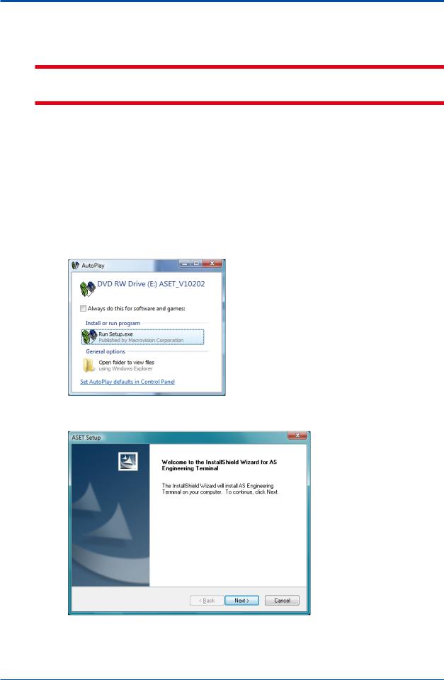
(2)Insert the installation disk into the CD-ROM drive.
(3)The install program is started automatically.
The following dialog box appears. Click [Run Setup.exe].
If it is not started automatically, run “setup.exe” file by double-clicking. The file is located under Disk1 directory.
(4)The “Welcome to the InstallShield Wizard for AS Engineering Terminal” dialog appears. Click [Next].
(5) Hereafter, install according to the displayed instruction.
IM 11B06C01-01E 5th Edition : Nov. 16, 2011-00
<Installing the Engineering Terminal>
 CAUTION
Might be necessary to restart the personal computer at the end of installation.
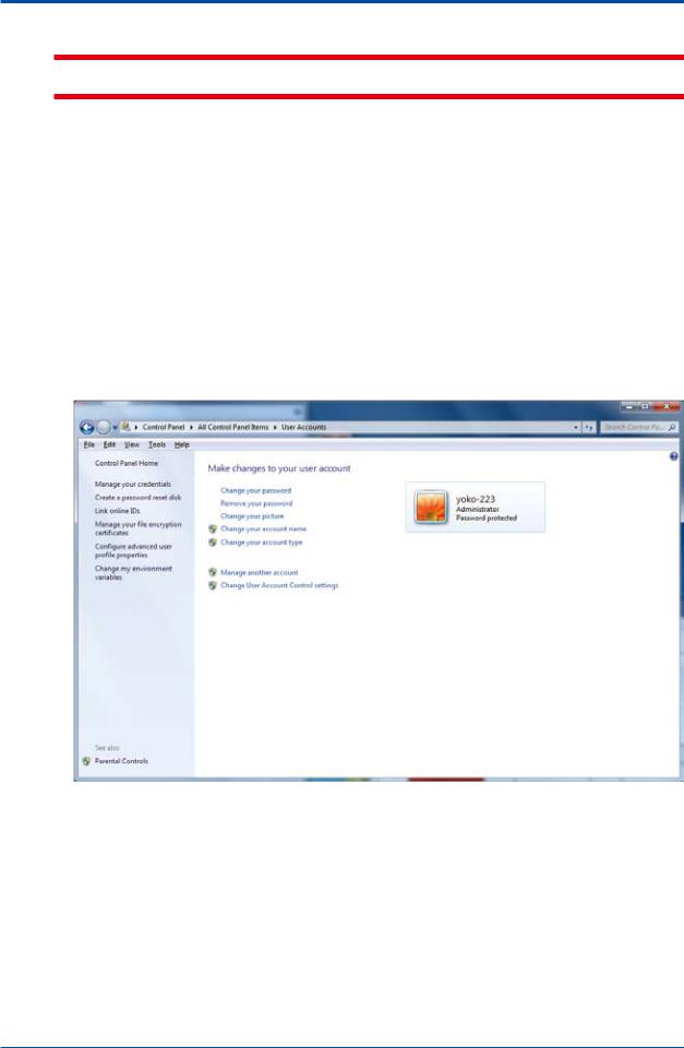
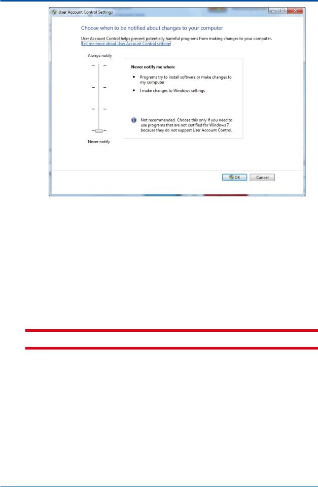
n Changing User Account Control settings
UAC helps prevent unauthorized programs from being installed on the system silently by viruses or malicious software. This feature is normally preferable, but in some cases, it may interfere with system operation and settings, e.g., UAC may block installation of some applications.
UAC can be disabled at the user’s discretion. Yokogawa is not responsible for any problems that may result from disabling UAC.
The UAC setting is enabled by default. To disable the setting, you must log on using an administrator account. All the following steps should be done as an administrator account.
(1) Open the Control Panel and then User Accounts.
Click [Change User Account Control settings]. The [Change User Account Control settings] dialog appears.
(2)In the [Choose when to be notified about changes to your computer], side to “Never notify”, and then click [OK].
IM 11B06C01-01E 5th Edition : Nov. 16, 2011-00
<Installing the Engineering Terminal>
Changing UAC setting is now complete.
nInstalling ASET on Computers Running OSs Other Than Windows 7
(1)Prepare a personal computer which fills the specification and turn on the power.
Start Windows.
(2)Insert the installation disk into the CD-ROM drive.
(3)The install program is started automatically.
The steps after this are the same as those for installing on computers running Windows 7 OS.
 CAUTION
Might be necessary to restart the personal computer at the end of installation.
IM 11B06C01-01E 5th Edition : Nov. 16, 2011-00
<Installing the Engineering Terminal>
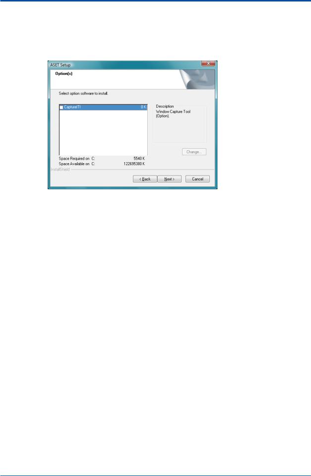
n CaptureIt! Installation
<Use the CaptureIt!>
You can select whether “CaptureIt!” capturing software at a below dialogue box in the installation of ASET.
You select whether to install “CaptureIt!” in the check column, and click on the “Next” button.
<Not use the CaptureIt!>
(1)Press the Print Screen key on your keyboard to copy the bitmap on the clipboard. It may be labeled [PrtScn].
When you want to capture an active window, press and hold down the “Alt” key, and press the “Print Screen” key on your keyboard to copy the bitmap on the clipboard.
(2)Open an image editing programme, such as Microsoft Paint.
Start the Paint accessory (Start -> Program -> Accessories -> Paint).
(3)Select [PASTE] from the [Edit] menu.
IM 11B06C01-01E 5th Edition : Nov. 16, 2011-00
<Installing the Engineering Terminal>
n Changes in the Windows Environment
When you install ASET, the Windows environment will change as follows:
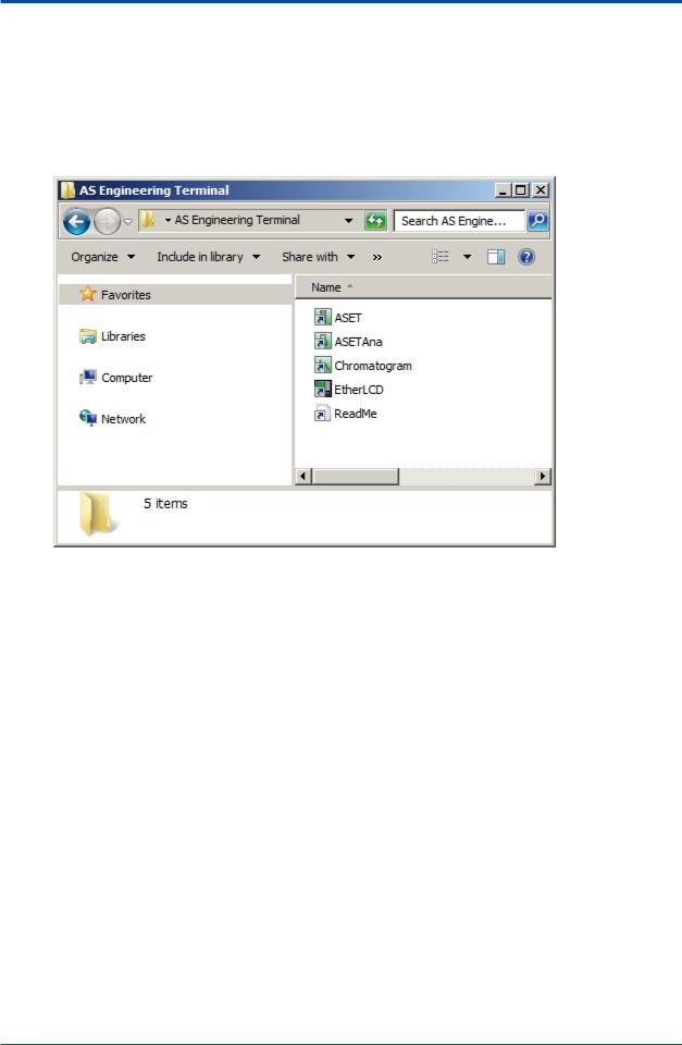
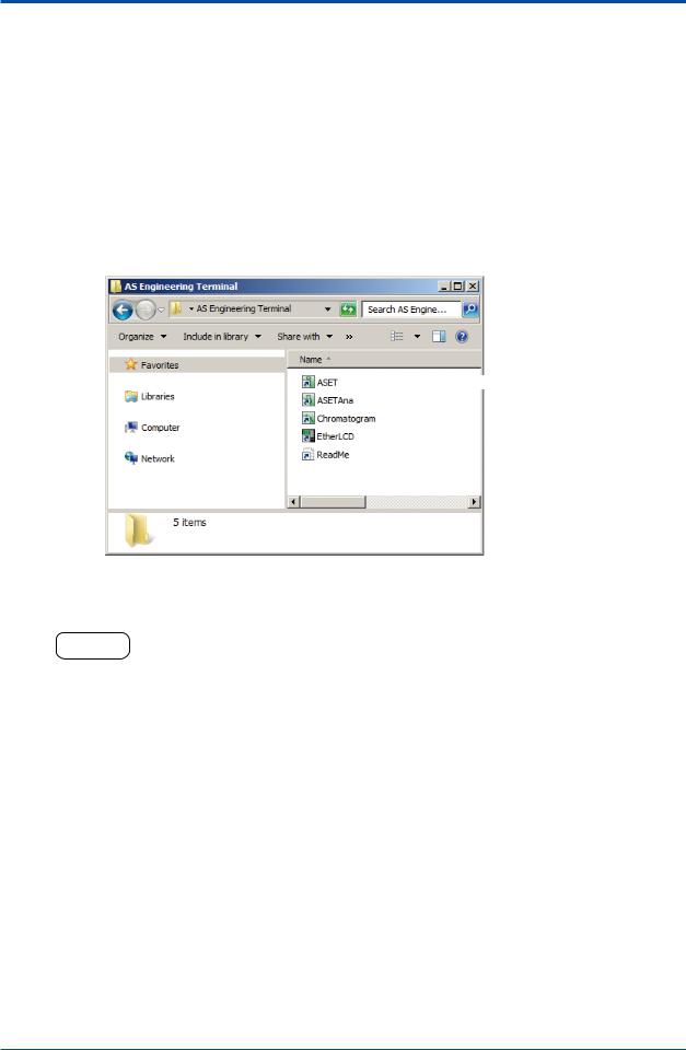
• “AS Engineering Terminal” group
When you install ASET, the “AS Engineering Terminal” group is newly registered. Five short-cut icons, namely “ASET”, “ASETAna”, “Chromatogram”, “EtherLCD” and “ReadMe” are registered in the “AS Engineering Terminal” group.
• ASETCFG.INI file andASET.INI file
When you installASET, the initialization files “ASETCFG.INI” and “ASET.INI” are created in the directory located in the Windows execution files. However, in cases whereASETCFG.INI and
ASET.INI already exist, such as when you are re-installing ASET, if you reply “No” to the question
“Do you wish to copy the initialization files?” the current files will be saved.
 TIP
TIP
About initialization files
•Do not directly edit an initialization file using a text editor, etc. unless Yokogawa specifically instructs you to do so. Otherwise, normal operation cannot be assured.
•If an initialization file has been directly edited according to Yokogawa's instructions, restart the application. The modified information will be only enables after restarting.
IM 11B06C01-01E 5th Edition : Nov. 16, 2011-00
<1. Overvies of the Engineering Terminal> |
1-1 |
1.Overview of the Engineering Terminal
This chapter gives an overview of the Engineering Terminal, as well as the basic facts that you need to know before operating the Engineering Terminal.
1.1Engineering Terminal
Before operating the Engineering Terminal, take a look at what kind of software the Engineering Terminal contains.
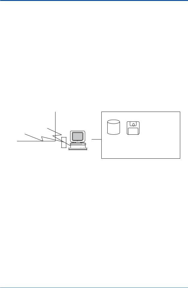
n Engineering Terminal
The ASET Engineering Terminal is software that is intended for collectively maintaining and monitoring analyzers from a personal computer. It links an analyzer server connected to multiple units of GC1000 Mark II and ASIU’s (hereafter called “analyzers”) to a personal computer via a communication link (Ethernet). Moreover, ASET can also be run on a PC serving as the analyzer server.
An overview of the Engineering Terminal follows.
[Field] |
[Instrument room/office] |
||||
Analyzer Analyzer |
|
||||
GC8000 GC1000 markII |
|
||||
|
|
••••• |
|
|
Engineering Terminal |
|
|
|
|
|
|
Hub 
Maintenance and monitoring of analyzers
Disk |
Printer |
|
|
|
|
|
|
|
|
|
|
|
|
|
|
• Saving and reading of |
• Printing the |
chromatogram and the |
chromatogram and |
results of analysis |
results of analysis |
• Reading and writing of |
|
setting parameters |
|
|
F1-1-1.ai |
n Engineering Terminal Features
The Engineering Terminal has the following features:
• Collective control of up to 64 analyzers
You can control up to 64 analyzers collectively from a single ASET via an analyzer server.
Moreover, up to 240 analyzers can be connected to the analyzer bus. By using multiple ASETs to control the analyzers in blocks, you can control all 240 analyzers.
• Continuous monitoring for extended periods
The analyzer server continuously saves data (chromatograms, analyzed values, and setting parameters) from the analyzers connected via the network. The ASET can call up continuous data stored in the analyzer server and display it, enabling you to perform continuous monitoring over extended periods.
• Data transfer using Ethernet communication
Using Ethernet, the large volumes of data stored in the analyzer server can be uploaded and downloaded, for each analyzer at a time, at the rate of 100 Mbps.ASET uses the standard file transfer protocol FTP, thus significantly improving the reliability of data transfer.
IM 11B06C01-01E 5th Edition : Nov. 16, 2011-00

<1. Overview of the Engineering Terminal> |
1-2 |
|
|
• Remote operation of the LCD window
A GC1000 analyzer’s LCD window is displayed as is on the PC monitor, enabling you to operate the LCD window for each analyzer from a remote location from the site.
•Analyzer Operation window allowing the operation status to be seen at a glance
The analyzer’s current operation mode, the operation status of the valves, detectors, etc. and a chromatogram are displayed in a single window (Analyzer Operation window); operation status can be checked at a glance. Moreover, you can change the operation mode, open and close valves, display a detailed chromatogram, and so on by simply clicking on the window.
• Displaying a detailed chromatogram and saving data
An overview of a chromatogram can be displayed in the Analyzer Operation window. In addition, you can display a detailed chromatogram in the Chromatogram Display window. Using this window, you can partially enlarge a chromatogram, change the scale, or save chromatogram data.
• Storing analysis data and creating graphs
The results of analysis using an analyzer are stored in the analyzer server. The analyzer server can store the peak names for up to 255 events and the analysis time for up to 250 events for each analyzer. Analysis data stored in the analyzer server can be read out and displayed on
a graph at any time, and data can also be saved to a file and then opened in general-purpose software such as Excel for more sophisticated data processing.
IM 11B06C01-01E 5th Edition : Nov. 16, 2011-00

<1. Overvies of the Engineering Terminal> |
1-3 |
1.2Engineering Terminal Group
Take a look at the types of software comprising the Engineering Terminal Group and the windows making up the Engineering Terminal.
n Software Configuration
The Engineering Terminal consists of the following six types of software:
Software Type |
Function |
Engineering Terminal |
This is the main core of the Engineering Terminal. |
(ASET) |
It develops various windows based on the Overview window that displays |
|
the operation status of multiple analyzers, as well as the analysis results. |
Analysis Results |
This window stores analysis results. It can be started independently if you |
window (ASETAna) |
wish to process analysis results saved in a file. |
CAPTURE IT! (CAPTIT) |
This is a tool for taking a hard copy. |
|
For more information, refer to the CAPTURE IT! manual. |
Ethernet LCD Emulator |
This software runs independently of the Engineering Terminal. It can |
(EtherLCD) |
emulate an analyzer LCD panel (i.e. operate in the same way as on the |
|
analyzer), allowing you to operate the analyzer panel from the PC. |
n Engineering Terminal Window Configuration
The Engineering Terminal consists of the following windows:
Window Type |
Function |
Overview window |
This window is provided to monitor the status of each analyzer connected to |
|
PCAS. It appears when ASET starts. |
Analyzer Overview |
The Analyzer Overview window displays the measurement status of each |
window |
GC module (hereafter referred to as GCM) in GC8000. Select the GCM you |
|
want to view the details in this window. |
|
From this window, open your desired subwindow (Analyzer Configuration, |
|
Analyzer Operation, Chromatogram, Analysis Results, or Alarm windows). |
Analyzer Operation |
The Analyzer Operation window is provided to operate or monitor the |
window |
operation status of an analyzer. |
|
Switch the window for each GCM. |
Chromatogram window |
The Chromatogram window is provided to monitor the current |
|
chromatogram or to display chromatograms stored in an analyzer |
|
server (hereafter referred to as PCAS). It is also used to reanalyze |
|
chromatograms. |
Analysis Results |
Displays the latest analysis results, concentration analysis history, retention |
windows |
time history or calibration coefficient history. Switch the window for each |
|
GCM or system (hereafter referred to as SYS). |
Alarm windows |
Displays alarm status and history of an analyzer. |
|
Switch the window for all analyzers or each GCM. |
Analyzer Configuration |
TheAnalyzer Configuration window is provided to display the definitions |
window |
of GCMs or SYSs in GC8000 or equipment configuration, such as oven, |
|
detectors, and valves. |
IM 11B06C01-01E 5th Edition : Nov. 16, 2011-00

<1. Overview of the Engineering Terminal> |
1-4 |
|
|
n Precautions for Using the LCD Emulator and Engineering Terminal
Observe the following precautions when using the LCD Emulator or Engineering Terminal.
• Analyzer data is controlled by the analyzer server.
It is essential that the Analyzer Server (PCAS) software is running normally. For PCAS, refer to the PCAS User’s Manual (IM 11B06B01-01E).
•Use the LCD Emulator or Engineering Terminal with an analyzer unit in remote mode.
If the analyzer unit is not in remote mode, you cannot start the LCD Emulator. You can use the Engineering Terminal’s display function even when the analyzer is in Local mode, but if you attempt to perform operation, a message appears indicating the operation was not accepted.
• The LCD Emulator and Engineering Terminal can be run at the same time.
Settings can be changed using the LCD Emulator while observing the operation status of analyzers on the Engineering Terminal.
However, there are some items that disable setting changes depending on the operation status, or that cause changes to be reflected in measurement at different timing.
IM 11B06C01-01E 5th Edition : Nov. 16, 2011-00
<2. Ethernet LCD Emulator Window> |
2-1 |
2.Ethernet LCD Emulator Window
The Ethernet LCD Emulator is software that reproduces an analyzer LCD panel in Windows.
It directly simulates the window and buttons of an LCD panel in the field in a Windows’window, providing both display and operations virtually identical to those of the LCD panel in the field.
With the LCD Emulator, you can connect to all analyzers that are connected via the network. This chapter gives an overview of the LCD Emulator window.
For more information, refer to User’s Manual of GC8000 (IM 11B08A01-01E) or GC1000 Mark II LCD Panel Operation Manual (IM 11B03A03-05E).
• Before Using the Ethernet LCD Emulator
Before starting the LCD Emulator, always check the following:
•Engineering Terminal is installed in the personal computer that is being used
•Analyzers and your PC are connected via the analyzer server
•Analyzer units are in Remote mode
2.1Starting LCD Emulator, Changing Analyzer,
and Exiting LCD Emulator
This section describes operations for starting an LCD Emulator, changing an analyzer, and exiting the LCD Emulator.
n Starting
The Ethernet LCD Emulator can be started while ASET or GCET is running. However, it cannot be started while ASMT, GCMT, ASLCD, or LCD is running.
A single analyzer can communicate with only one PC at a time using Ethernet LCD Emulator. If a specified analyzer is communicating with another PC, a message appears informing you that communication cannot be connected.
Note that the Ethernet LCD Emulator cannot be connected to ASIU.
You can start up to four Ethernet LCD Emulators simultaneously with a single PC. If you attempt to start a 5th Ethernet LCD Emulator, a message box appears informing you that more Ethernet LCD Emulators cannot be started.
•Operation procedure
(1)An Ethernet LCD Emulator can be started by clicking Windows’ Start button, selecting All Programs, and clicking on the EtherLCD item in the AS Engineering Terminal group. Or if an
EtherLCD short-cut icon 
is provided in the window, you can double click it instead.
IM 11B06C01-01E 5th Edition : Nov. 16, 2011-00
<2. Ethernet LCD Emulator Window> |
2-2 |
|
|
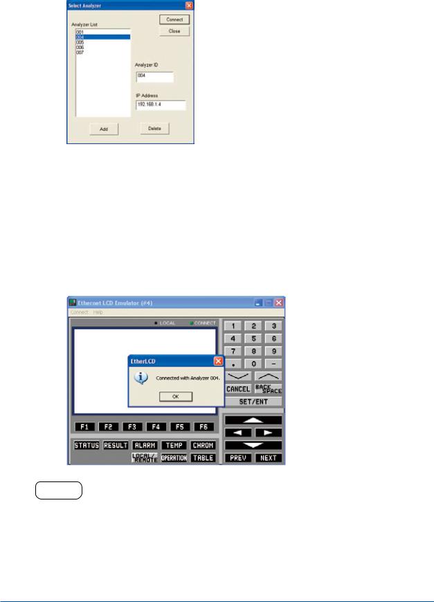
(2)If the number of analyzers registered is zero or two or more, the Select Analyzer dialog box appears. Select the analyzer you wish to connect.
If the number of registered analyzers is one, the Ethernet LCD Emulator starts communication with that analyzer directly, without displaying the Select Analyzer dialog box.
F0201.ai
(3)Choose the analyzer ID of the analyzer you wish to connect to from the list displayed.
(4)Click the Run button.
The cursor changes to a sandglass icon and the Ethernet LCD Emulator waits for the result of the communication connection.
When the communication connection becomes established, the Ethernet LCD Emulator’s CONNECT indicator is displayed in green, informing you that it has been connected to the analyzer concerned. After a while, the Initialize window (status window) of the analyzer appears. The selected analyzer ID will be indicated at the right of the caption in the form of “#XXX.”
If communication connection fails to be established, a message box to that effect appears. The CONNECT indicator on the window remains blacked out.
F0202.ai
HELP !
•If the message “Connection failed” is displayed, it is possibly due to one of the following seven causes:
(1)Wiring to the analyzer is incorrect.
Countermeasure: Check the wiring between the analyzer and the analyzer server, and between the analyzer server and the PC.
(2)The Ethernet card is not functioning properly.
Countermeasure: Confirm that the Ethernet card operates normally.
(3)No TCP/IP has been installed in the OS. Countermeasure: Install TCP/IP to the OS.
IM 11B06C01-01E 5th Edition : Nov. 16, 2011-00
<2. Ethernet LCD Emulator Window> |
2-3 |
|
|
(4)The analyzer server IP address is illegal.
Countermeasure: Click on the Select Server command in the Connect menu to open the Select Server dialog box and re-enter the correct IP address.
(5)You have chosen the analyzer ID of an analyzer not connected to the analyzer server. Countermeasure: Choose the correct analyzer ID.
(6)The selected analyzer is in Local mode.
Countermeasure: Change the mode of the analyzer unit’s LCD panel to Remote and try to make the communication connection again.
(7)Communication connection with the analyzer cannot be achieved temporarily due to causes such as noise.
Countermeasure: Execute the Connect command from the Connect menu again.
(5)Click the OK button.
The LCD Emulator window appears.
F0203.ai
HELP !
If the analyzer unit’s LCD panel is being operated while the LCD Emulator is being used, a message stating “Exit command has been received” appears and communication with the analyzer will be disconnected.
To reactivate the LCD Emulator window in this case, wait for panel operation of the analyzer unit to be finished, then re-execute the communication connection.
IM 11B06C01-01E 5th Edition : Nov. 16, 2011-00
<2. Ethernet LCD Emulator Window> |
2-4 |
|
|
n Changing Analyzers
•Operation procedure
(1)Click on the Select Analyzer command in the Connect menu.
The dialog box for selecting the analyzer ID of a new analyzer to be connected appears.
F0204.ai
(2)Choose the analyzer ID of the analyzer you wish to connect to from the list.
(3)Click the Run button.
This connects communication with the selected analyzer.
n Editing the List of Analyzer IDs
The method of editing information in the List of Analyzer IDs in the Analyzer select dialog box is as follows:
•Registration
(1)Enter the analyzer ID, tag name (if necessary), and IP address into the respective fields.
The available analyzer IDs are from 1 to 240.
(2)Click the Register button. The entered information is added to the List of Analyzer IDs.
•Editing
(1)Select the analyzer ID to be edited from the List of Analyzer IDs.
(2)Change the information in the Analyzer select dialog box.
(3)Click the Register button.
•Deletion
(1)Select the analyzer ID of the analyzers to be deleted from the analyzer list.
(2)Click the Delete button. This causes the selected analyzer ID to be deleted from the List of Analyzer IDs.
IM 11B06C01-01E 5th Edition : Nov. 16, 2011-00
<2. Ethernet LCD Emulator Window> |
2-5 |
|
|
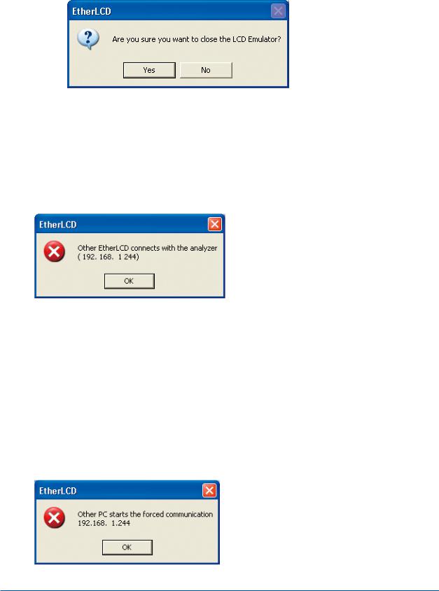
n Exiting the LCD Emulator
•Operation procedure
(1)Click on the Exit command in the Connect menu.
The dialog box asking if you wish to exit the LCD Emulator appears.
F0205.ai
(2)Click the Yes button.
This disconnects communication with the analyzer, exiting the LCD Emulator.
n Limitation on the Number of Users to be Connected Simultaneously
The analyzer cannot communicate with multiple LCD Emulators at the same time. If a user attempts to make a communication connection with a particular analyzer using an LCD Emulator while another user is already communicating with that analyzer using an LCD Emulator, the second connection cannot be established. In this case, a message box appears indicating the IP address of the currently connected PC.
F0207.ai
n Forced Connection
Forced connection is a connection means to establish a communication connection even if the analyzer concerned is communicating by Ethernet with the Ethernet LCD Emulator on another PC.
For example, assume that PC1 with the IP address XXX.XXX.XXX.100 has started an Ethernet LCD Emulator and has been communicating with an analyzer. In this case, if PC2 with the IP address XXX.XXX.XXX.101 starts an Ethernet LCD Emulator to make a forced connection with that analyzer, connection with PC1 is terminated and a dialog box stating “Communication is disconnected due to forced connection from XXX.XXX.XXX.101” appears on PC1. Then communication between PC2 and the analyzer concerned will be started. (Last priority)
Moreover, if another PC has started an LCD Emulator to make a serial connection and is conducting serial communication with an analyzer unit’s LCD, forced connection is still possible. (In this case, proceeding with serial communication will be interrupted.)
F0208.ai
IM 11B06C01-01E 5th Edition : Nov. 16, 2011-00
<2. Ethernet LCD Emulator Window> |
2-6 |
|
|
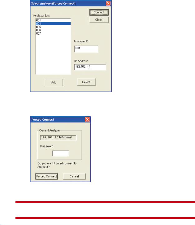
•Operation procedure
(1)Click on the Forced Connect command in the Connect menu. The dialog box for typing a password appears.
About the password refer to User’s Manual of GC8000 (IM 11B08A01-01E) or Password Manual (IM 11B03A03-07E).
(2)Enter the password and click the Run button.
When a user level C password is entered, in case the number of analyzers registered is 0 or 2 or more, the dialog box of Analyzer selection (Forced connect) appears.
Here, select the analyzer to be forced-connected.
When the number of analyzers registered is 0, the analyzer is added.
When the number of analyzers registered is 1, the confirmation message (to be forcedconnected) comes up.
F0210.ai
(3)When the analyzer requested the force connection is under the connection with the other
Ethernet LCD emulator, the dialog box of the force connection appears. Confirming the IP address which is now connecting, enter a user level C password again, then click Force connect button.
F0211.ai
 CAUTION
If another user performs forced connection during this establishment of forced connection, the original attempt at forced connection communication will be disconnected.
IM 11B06C01-01E 5th Edition : Nov. 16, 2011-00

<2. Ethernet LCD Emulator Window> |
2-7 |
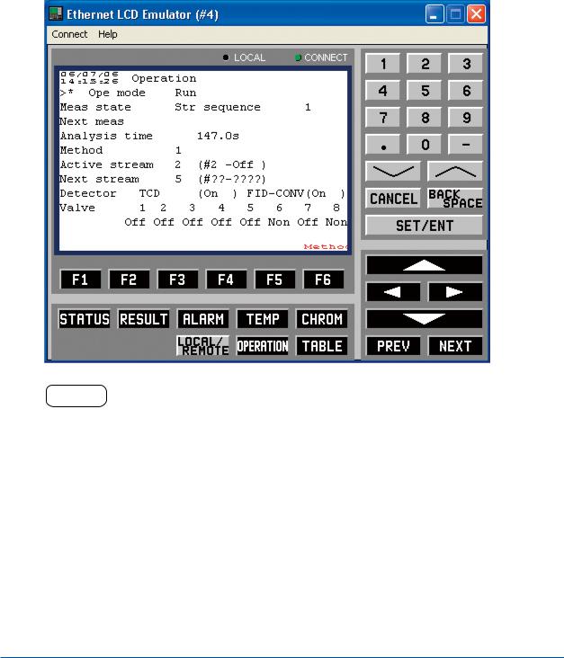
2.2Basic Operation
The LCD Emulator window is identical to the LCD panel for both display and operations. Buttons on the window can be operated using a mouse, and keyboard-based one-touch operation is also possible.
n Window Configuration
The following shows an LCD Emulator window configuration.
• GC8000
Status Menu (1/2)
AI Status
AO Status
DI Status
DO Status
Remote AO Status
Remote DO Status
Revision number
Ethernet Status
Alarm Status
• GC1000 MarkII
LCD display |
LED indicator section |
Setting entry keys
Function keys |
|
|
|
Window changing keys |
F0209.ai |
||
IM 11B06C01-01E 5th Edition : Nov. 16, 2011-00
<2. Ethernet LCD Emulator Window> |
2-8 |
|
|
n Window Operation
The Ethernet LCD Emulator can realize all the display and operation features of an analyzer’s LCD panel with the exception of the following:
ALARM indicators DISPLAY RESET key
• Mouse operation
Move the mouse cursor over the key you wish to operate and then click the mouse’s left button. This activates the keys to be operated in the same way as those on the LCD panel.
• Keyboard operation
Keys on each panel correspond to the keys on the keyboard as follows:
Pressing any of these keys facilitates key operation in the same way as those on the LCD panel.
Panel display and keys on the keyboard
|
Window Display |
|
Keys on Keyboard |
|||
Function |
|
[F1] to [F6] |
[F1] to [F6] |
|||
keys |
|
|||||
|
GC8000 |
|
|
|
|
|
|
|
[Status] |
|
[SHIFT] + [F1] |
||
|
|
[Password] |
[SHIFT] + [F6] |
|||
Window |
|
[Operation] |
[SHIFT] + [F7] |
|||
|
[TEMP] |
|
[SHIFT] + [F8] |
|||
changing |
|
|
||||
GC1000 MarkII |
|
|
|
|
||
keys |
|
|
|
|
||
|
|
[STATUS] |
[SHIFT] + [F1] |
|||
|
|
[RESULT] |
[SHIFT] + [F2] |
|||
|
|
[ALARM] |
|
[SHIFT] + [F3] |
||
|
|
[TEMP] |
|
[SHIFT] + [F4] |
||
|
|
[CHROM] |
[SHIFT] + [F5] |
|||
|
|
LOCAL/ |
|
[SHIFT] + [F6] |
||
|
|
REMOTE |
||||
|
|
|
|
|||
|
[OPERATION] |
[SHIFT] + [F7] |
||||
|
|
[TABLE] |
|
[SHIFT] + [F8] |
||
|
Alphanumeric keys |
Alphanumeric keys |
||||
|
[ |
] |
[ |
] |
[Page Down] |
[Page Up] |
|
|
[CANCEL] |
[ESC] |
|||
Setting |
|
BACK |
|
BACK |
||
|
SPACE |
|
SPACE |
|||
entry keys |
|
|
||||
|
[SET/ENT] |
[ENTER] |
||||
|
|
|||||
|
|
[ |
|
] |
|
|
|
[ |
] |
[ |
] |
Cursor movement keys |
|
|
|
[ |
|
] |
|
|
|
|
[PREV] |
|
[CTRL] + [P] |
||
|
|
[NEXT] |
|
[CTRL] + [N] |
||
|
|
|
|
|
|
T0201.ai |
IM 11B06C01-01E 5th Edition : Nov. 16, 2011-00
<3. Overview Window> |
3-1 |
3.Overview Window
The Overview window facilitates status display and the operation of two types of analyzers: GC1000 Mark II and ASIU. There are slight differences in window display and the available commands according to the analyzer type.
This chapter describes those areas both analyzer types have in common, such as how to start/ exit the Overview window, setting window displays, and reading and writing parameters.
For individual information pertaining to each analyzer type, see Chapter 4 for GC8000, Chapter 5 for GC1000 Mark II and Chapter 6 for ASIU.
The following shows the relationship between the windows:
|
|
|
|
|
|
|
|
Overview |
|
|
Analyzer |
|
|
|
window |
|
|
Overview |
|
|
|
|
|
||||
|
|
|
|
window |
|
|
|
|
|
|
|
|
|
(Single analyzer mode does |
(Only for GC8000) |
|
|
|||
not have “overview window” ) |
|
|
|
|||
|
|
|
|
|
|
|
|
|
|
|
|
|
|
|
|
|
|
|
|
|
|
|
|
|
|
|
|
|
|
|
|
|
|
|
|
|
|
|
|
|
|
|
|
|
|
|
|
|
|
|
|
|
|
|
|
|
|
|
|
|
|
|
|
|
|
|
|
|
|
|
|
|
|
|
|
|
|
|
|
|
|
|
|
|
|
|
|
|
|
|
|
|
|
|
|
|
|
|
|
|
|
|
|
|
|
|
|
|
|
|
|
|
|
|
|
|
|
|
Analyzer
Operation
window
Chromatogram
window
Analysis Results
windows
Alarm windows
Analyzer
Configuration
window
ASIU Operation
window
Short-term Trend window
GC8000
GC1000 MarkII
GC8000
GC1000 MarkII
GC8000
GC1000 MarkII
GC8000 GC1000 MarkII ASIU
GC8000
ASIU
ASIU
F0301.ai
• Before Using ASET
Before starting the Engineering Terminal, always check the following items:
•Engineering Terminal is installed in the personal computer that is being used
•Analyzers and your PC must be connected via an analyzer server
IM 11B06C01-01E 5th Edition : Nov. 16, 2011-00
<3. Overview Window> |
3-2 |
3.1Starting and Exiting the Engineering
Terminal
This section describes how to start and exit the Engineering Terminal.
n Starting
The Engineering Terminal can operate just one window.
•Operation procedure
(1)Turn ON the personal computer’s power supply, start Windows, and display the Engineering Terminal Group window on the Desktop.
 Engineering Terminal icon
F0302.ai
(2)Double click on the Engineering Terminal icon.
This establishes communication connection with the analyzer server, causing the Overview window to appear.
HELP !
If the Engineering Terminal fails to establish communication connection with the analyzer server, the message “Connection failed” appears. For possible causes of this and steps to be taken, see HELP in section 2.1, “Starting LCD Emulator, Changing Analyzer, and Exiting LCD Emulator.”
IM 11B06C01-01E 5th Edition : Nov. 16, 2011-00
Loading...