


 Loading...
User's
Manual
GC1000 Mark II
Process Gas Chromatograph
Overview
IM 11B03A03-01E
IM 11B03A03-01E
3rd Edition

<Toc> <Ind> <Rev> |
<Introduction> |
i |
Notice
●RegardingThis Manual
1.This Manual should be passed on to the end user.
2.Read this manual carefully and fully understand how to operate this product before you start operation.
3.Yokogawa makes no warranty of any kind with regard to this material, but not limited to, implied warranties of merchantability for particular purpose.
4.All rights reserved. No part of this manual may be reproduced in any form without Yokogawa’s written permission.
5.Great effort has been expended to ensure that the descriptions in this manual are correct. Should you, however, come across a questionable area or note an inconsistency, a telephone call or letter to Yokogawa.co.,ltd. noting the questionable area would be highly appreciated.
6.The contents of this manual are subject to change without prior notice.
●Regarding Protection,Safety,and Prohibition Against Unauthorized Modification.
1.For the protection and safe use of the product and the system controlled by it, be sure to follow the instructions on safety described in this manual when handling the product. In addition, if you handle the product in contradiction to these instructions, our company does not guarantee safety.
2.The following safety symbol marks are used on the product concerned or in this Manual :
 WARNING
A WARNING sign denotes a hazard. It calls attention to procedure, practice, condition or the like, which, if not correctly performed or adhered to, could result in injury or death of personnel.
 CAUTION
A CAUTION sign denotes a hazard. It calls attention to a procedure, practice, condition or the like, which, if not correctly performed or adhered to, could result in damage to or destruction of part or all of the product.
IMPORTANT:
Indicates that operating the hardware or software in this manner may damage it or lead to system failure.
NOTE:
Draws attention to information essential for understanding the operation and features.
TIP:
Gives information that complements the present topic.
Media No. IM 11B03A03-01E |
3rd Edition : Aug. 2006 (YK) |
IM 11B03A03-01E 3rd Edition : Aug. 23. 2006-00 |
All Rights Reserved Copyright © 2001, Yokogawa Electric Corporation |
|
|

<Toc> <Ind> <Rev> |
<Introduction> |
ii |
See Also:
Gives the reference locations for further information on the topic.
Protective ground terminal:
In order to provide protection against electrical shock in case of a fault. This symbol indicates that the terminal must be connected to ground prior to operation of equipment.
Function ground terminal:
In order to provide protection against noise. This symbol indicates that the terminal must be connected to ground prior to operation of equipment.
Alternating current
Indicates the power switch state “ON”.
Indicates the power switch state “Stand - by”.
Indicate the power switch state “OFF”.
3.If protection / safety circuits are to be used for the product or the system controlled by it, they should be installed outside of the product.
4.When you replace parts or consumables of the product, use those specified by our company.
5.Do not modify the product.
●Exemption from Responsibility
1.Yokogawa Electric Corporation does not make any warranties regarding the product except those mentioned in the WARRANTY that is provided separately.
2.Yokogawa Electric Corporation assumes no liability to any party for any loss or damage, direct or indirect, caused by the use or any unpredictable defect of the product.
●Regarding Software and set including Software Supplied byYOKOGAWA
1.Yokogawa makes no other warranties expressed or implied except as provided in its warranty clause for software supplied Yokogawa.
2.Use this software with one specified computer only.
You must purchase another copy of the software for use with each additional computer.
3.Copying this software for purposes other than backup is strictly prohibited.
4.Store the streamer or floppy disk (original medium) in a secure place.
5.Reverse engineering such as the disassembly of software is strictly prohibited.
6.No portion of the software supplied by Yokogawa may be transferred, exchanged, or sublet or leased for use by any third party without prior permission by Yokogawa.
IM 11B03A03-01E 3rd Edition : Aug. 23. 2006-00

<Toc> <Ind> <Rev> |
<Introduction> |
iii |
Warning/CautionLabels
●To ensure safety operation of this equipment,warning/caution labels are attached on the equipment as follows. Check these labels for your safety operation.

 D
D
A
C
B
E
[Left side] |
[Front] |
[Right side] |
|
[Back] |
|
F0001.EPS
A B
C
The inside of the enclosure is high temperature after turning off the power. Don’t touch the inside of the enclosure or the compponents, the protective gas should be suoolied for more than one hour after turning off the power.
D E
F0002.EPS
IM 11B03A03-01E 3rd Edition : Aug. 23. 2006-00

<Toc> <Ind> <Rev> |
<Introduction> |
iv |
Introduction
Thank you for purchasing the GC1000 Mark II process gas chromatograph.
This manual describes the technical information on overview of Model GC1000D / GC1000S / GC1000T / GC1000E / GC1000W / GC1000C (Hereafter, it is abbreviated as GC1000 Mark II) Process Gas Chromatograph.
Please lead the following respective documents before installing and using the GC1000 Mark II system.
● Documents Related to the GC1000 Mark II Process Gas Chromatograph
1. Instruction manuals
The product comes with the following instruction manuals.
■Instruction manuals that do not depend upon the specifications of the product
(1)Overview (IM 11B03A03-01E)
(2)Basic Operation and Startup (IM 11B03A03-02E)
(3)Maintenance and Inspection Manual (IM 11B03A03-04E)
(4)LCD Panel Operation Manual (IM 11B03A03-05E)
(5)Alarm Message Manual (IM 11B03A03-06E)
(6)Password Manual (IM 11B03A03-07E) and Installation Manual (TI 11B03A03-13E)
■Instruction manuals that depend upon the specifications of the product
(1)GCMT Gas Chromatograph Maintenance Terminal Software Package Operation Guide (IM 11B03G03-03E)
(2)Capture It! Manual (IM 11B3G1-02E)
■Instruction manuals for related products
(1)PCAS PC Analyzer Server Software (IM 11B06B01-01E)
(2)ASET Analyzer Server Engineering Terminal Software (IM 11B06C01-01E)
(3)GCET GC Engineering Terminal Software (IM 11B06D01-01E)
(4)ASGW Analyzer Server Gateway Software (IM 11B06E01-01E)
(5)ASIU Analyzer Server Interface Unit Software (IM 11B06F01-01E)
IM 11B03A03-01E 3rd Edition : Aug. 23. 2006-00
<Toc> <Ind> <Rev> |
<Introduction> |
v |
2. Operation Data
Operation data is supplied with the operation manuals in the delivered package and contains the following required to use the gas chromatographs.
●Process conditions and measurement range
●Instrument specifications and operating conditions
●Standard sample for calibration
●Column system and column
●Miscellaneous data
Chromatogram, base line, repeatability, power supply voltage variation, etc.
●Analyzer flow diagram and installation
●Parts composition table
●General connection diagram
●Sampling system diagram (only if supplied by Yokogawa)
●Is the System Ready?
Before reading this manual, the following preparations must have been completed.
●The system must be unpacked and installed in the correct place.
●The piping for the utility gases such as carrier and calibration gases must be completed, followed by leak checking.
●The wiring for the power supply and others must be completed.
If these have not been completed yet, see the Installation Manual (TI 11B03A03-13E). After completion, return to this manual and do the following:
●If the system power is on, turn off the power.
●Shut off all the gases at the flow control units.
Please read the following respective cautions (General Precautions, Caution of using Explosion-Protection Instruments, on Piping Construction, and on Piping Work) before installing and using the GC1000 system.
IM 11B03A03-01E 3rd Edition : Aug. 23. 2006-00
<Toc> <Ind> <Rev> |
<Introduction> |
vi |
● General Precautions
 WARNING
(1)In order to analyze gases, process gas chromatographs use a sample of the process gas and utility gases.
Since these gases are typically combustible, combustion-sustaining, toxic, odorous, resolvable, polymerizing, or corrosive, refer to the “Safety Information” in our approval drawings and others to ensure safety thoroughly before using these analyzers.
(2)Up to two protection systems, each of which weighs approximately 10 kg, are installed on top of the GC1000. Therefore, the center of gravity is higher than the center of the analyzer body.
Take great care when carrying and installing (pipingwiring) the GC1000. The GC1000 must be carried and installed very carefully (including piping and wiring) by more than one person (at least four people are recommended).
(3)Since the GC1000 are precision instruments, take care when handling not to jolt of knock them.
(4)Use the GC1000 within the range of your purchase specifications.
Yokogawa assumes no responsibility for problems resulting from use by the customer outside the purchase specifications.
If the GC1000 need to be modified or repaired, please contact your nearest Yokogawa representative. Yokogawa assumes no responsibility for results where the customer or any third party has attempted to modify or repair these products.
(5)When touching LCD Panel switches
When touching LCD Panel switches, first, discharge Electro Static Charge of the body.
Then, touch the LCD Panel switches. If not, LCD display may be changed by Electro Static Discharge.
IMPORTANT:
(1)Read the attached instruction manual before operating the GC1000
(2)The instruments must be installed and operated according to the installation manual, instruction manual, approval drawings, and operation data.
IM 11B03A03-01E 3rd Edition : Aug. 23. 2006-00

<Toc> <Ind> <Rev> |
<Introduction> |
vii |
● CAUTIONS OF USING EXPLOSION-PROTECTION INSTRUMENTS
The GC1000 Process Gas Chromatographs are designed to protect against explosion. When these analyzers are used in a hazardous area, observe the following precautions.
Since the applicable standard differs depending on the specifications of the analyzer to be used, check the specifications of your analyzer.
(1) Kinds of explosion protection
To assure explosion protection, the GC1000 Process Gas Chromatographs have a pressurized and flameproof construction, or type X purging and explosionproof construction meeting the following standards :
<GC1000D / GC1000S>
•JIS Expd IIB + H2 T1 (programmed-temperature oven 320˚C max., isothermal oven 225˚C max., liquid-sample valve 250˚C max.)
•JIS Expd IIB + H2 T2 (programmed-temperature oven 225˚C max., isothermal oven 225˚C max., liquid-sample valve 225˚C max.)
•JIS Expd IIB + H2 T3 (programmed-temperature oven 145˚C max., isothermal oven 145˚C max., liquid-sample valve 145˚C max.)
•JIS Expd IIB + H2 T4 (programmed-temperature oven 95˚C max., isothermal oven 95˚C max., liquid-sample valve 95˚C max.)
<GC1000W / GC1000C>
CENELEC (ATEX directive) certified : Group II Category 2G
•EEx pd II B +H2 T1 (programmed-temperature oven 320°C max, isothermal oven 225°C max., liquid-sample valve 250°C max.)
•EEx pd II B +H2 T2 (programmed-temperature oven 225°C max, isothermal oven 225°C max., liquid-sample valve 225°C max.)
•EEx pd II B +H2 T3 (programmed-temperature oven 145°C max, isothermal oven 145°C max., liquid-sample valve 145°C max.)
•EEx pd II B +H2 T4 (programmed-temperature oven 95°C max, isothermal oven 95°C max., liquid-sample valve 95°C max.)
<GC1000T / GC1000E>
FM |
Type X purging and Explosionproof for CLI, DIV1, GPS B, C & D, NEMA3R. |
|
Type Y purging and Type X purging for CLI, DIV1, GPS.B, C & D, NEMA3R. |
•T1 (programmed-temperature oven 320˚C max., isothermal oven 225˚C max., liquidsample valve 250˚C max.)
•T2 (programmed-temperature oven 225˚C max., isothermal oven 225˚C max., liquidsample valve 225˚C max.)
•T3 (programmed-temperature oven 145˚C max., isothermal oven 145˚C max., liquidsample valve 145˚C max.)
•T4 (programmed-temperature oven 95˚C max., isothermal oven 95˚C max., liquidsample valve 95˚C max.)
IM 11B03A03-01E 3rd Edition : Aug. 23. 2006-00

<Toc> <Ind> <Rev> |
<Introduction> |
viii |
CSA |
Type X purging and Explosionproof for CLI, DIV1, GPS B, C & D, NEMA3R. |
|
|
Type Y purging and Type X purging for CLI, DIV1, GPS.B, C & D, NEMA3R. |
|
•T1 (programmed-temperature oven 320˚C max., isothermal oven 225˚C max., liquidsample valve 250˚C max.)
•T2 (programmed-temperature oven 225˚C max., isothermal oven 225˚C max., liquidsample valve 225˚C max.)
•T3 (programmed-temperature oven 145˚C max., isothermal oven 145˚C max., liquidsample valve 145˚C max.)
•T4 (programmed-temperature oven 95˚C max., isothermal oven 95˚C max., liquidsample valve 95˚C max.)
(2)Precautions for Explosionproof section (The analyzer with optional code "FM/CSA Type Y purging" does not have the explosionproof section.)
When handling the screws on the cover of the Protection system, note the following to avoid damaging the screws since they cannot be repaired.
(1)The enclosure is pressurized. Before removing the cover, reduce the internal pressure by loosening the sealing plug for wiring on the enclosure or relevant means.
(2)When removing the cover, prevent any dirt or foreign matter from contaminating the screw part.
(3)When installing the cover, tighten the screws by hand ; never use tools.
(4)Since the screws are coated with MOLYKOTE, do not lubricate them.
(3)Precautions when using hydrogen gas
When using hydrogen gas as the carrier gas, the FID or FPD combustion gas, to ensure safety, install the analyzer in a location equipped with a ventilator or where there is sufficient ventilation. Make sure there are no gas leaks from the pipe joints and inspect for leaks.
(4) Installation site and environment
The analyzer specifications allow it to be used in hazardous areas as defined by Zone1 IIB + H2T1, T2, T3, T4 (JIS / CENELEC) or DIV1, GPS B, C & D, T1, T2, T3, T4 (FM / CSA). However, never install the analyzer in an area where the density of explosive gas persists for a long time.
(5) Wiringworks
Model GC1000D / GC1000S, analyzer obtains explosion proof authorization by the complete set including metal fittings of the attachment.
When performing wiring, always use the attached sealing fittings and flameproof packing adapter.
IM 11B03A03-01E 3rd Edition : Aug. 23. 2006-00

<Toc> <Ind> <Rev> |
<Introduction> |
ix |
(6) Maintenance and inspection
During usual maintenance and inspection, it is not necessary to check the explosionprotected section.
Before opening the door of the explosion-protected section for maintenance and inspection, be sure to turn off the power. After completing maintenance and checks, close the door completely then turn on the power after checking that the specified explosion protection performance is guaranteed. The parts to be checked are described in the Maintenance and Inspection Manual (IM 11B03A03 - 04E).
If any of the following damage occurs, contact a Yokogawa sales representative or the Yokogawa sales division
(1)If the screws securing the Protection System (explosionproof construction) are damaged
(2)If the exterior or light transmission section of the enclosures is damaged
(3)If packings are cracked or conspicuously deformed
(7)Override function (The analyzer with optional code "FM/CSA Type Y
purg ing" does not have this function.)
 WARNING
•When the override function is used, Analyzer becomes an ignition source and the high temperature and the high voltage part will be exposed.
•Please confirm that in the ambient atmosphere, the concentration of explosive gases is less than the allowable limit, by using a gas detector.
To return to the normal operation, turn off “the override switch” and then close the door as it was before turning on power.
In this analyzer, if the pressure of the pressurized / type X purged enclosure system (oven, electronic section) drops while the power is on, the pressurized explosion protection section is activated to stop power supply. Therefore, in case of opening the door of the oven or of the electronic section inadvertently, for maintenance, while the power is on, the protection system is activated to cut off the power.
The “override function” intensively releases this function of protection system.
The override switch is installed in section.
(8) Replacing parts
Always use parts specified by Yokogawa when replacing parts, for replacement, refer to the Maintenance and Inspection Manual (IM 11B03A03 - 04E).
IM 11B03A03-01E 3rd Edition : Aug. 23. 2006-00
<Toc> <Ind> <Rev> |
<Introduction> |
x |
(9) Operation
 WARNING
<CENELEC>
*Only trained persons may use this instrument in a hazardousl location.
*Do not open when energized.
<FM>
For type X purging:
*This equipment contains components that operate at high temperature. The equipment shall be deenergized for 60 minutes to permit those components to cool before the enclosure is opened unless the area is demonstrated to be nonhazardous at the time.
*Enclosure shall not be opened unless the area is known to be nonhazardous, or unless all devices within have been de-energized.
*Power shall not be restored after enclosure has been opened until enclosure has been purged for 12 minutes. (When the internal pressure is restored, the system automatically purges over the 12 minutes, then turns on the power again.)
For explosionproof enclosure:
*Seal all conduits within 18 inches
*Open circuit before removing cover. For type Y purging:
*Enclosure shall not be opened unless the area is known to be non-hazardous, or unless all devices within have been de-energized. Power shall not be restored after enclosure has been opened until enclosure has been purged for 12 minutes at specified pressure indicated by the pressure gauge labeled “EL.BOX” in the pressure and flow control section.
*Alarm shall be provided and connected to alarm contact output.
(a)The alarm shall generate a visual or audible signal that attracts attention
(b)The alarm shall be located at constantly attended location.
(c)Electrical alarms shall be approved for the location in which they are installed.
IM 11B03A03-01E 3rd Edition : Aug. 23. 2006-00

<Toc> <Ind> <Rev> |
<Introduction> |
xi |
<CSA>
For type X purging:
*This equipment contains components that operate at high temperature. The equipment shall be deenergized for 60 minutes to permit those components to cool before the enclosure is opened unless the area is demonstrated to be nonhazardous at the time.
*Enclosure shall not be opened unless the area is known to be non-hazardous, or unless all devices within the enclosure have been de-energized. Power must not be restored after enclosure has been opened until enclosure has been purged for 12 minutes at a flow rate of 0.05m3/min.
*Power will automatically be removed when purge pressure falls below 40 mm (1.6 in) of water column.
For explosionproof enclosure:
*A seal shall be installed within 50 cm of the enclosure.
*Open circuit before removing cover.
For type Y purging:
*Enclosure shall not be opened unless the area is known to be non-hazardous, or unless all devices within the enclosure have been de-energized. Power must not be restored after enclosure has been opened until enclosure has been purged for 12 minutes at a flow rate of 0.05m3/minute min.
*Remove power below 40mm (1.6in) of water column.
Take care not to generate mechanical spark when accessing to the instrument and peripheral devices in hazardous locations.
Do not press prick the keyboard of LCD panel (operation and display section) using such as knives and sticks.
(10) Maintenance and Repair
The instrument modification or parts replacement by other than authorized representative of Yokogawa Electric Corporation is prohibited and will void the approval of Factory Mutual Research Corporation and CSA certification and CENELEC certification .
IM 11B03A03-01E 3rd Edition : Aug. 23. 2006-00
<Toc> <Ind> <Rev> |
<Introduction> |
xii |
● Precautions Against Electrostatic Problems
The GC1000 system uses numerous IC components. When handling cards with IC components mounted on them for maintenance or setting changes, take full precautions against electrostatic problems.
These precautions are summarized below.
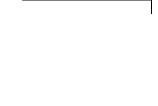
(a)When storing or carrying cards, enclose them in a conductive bag or antistatic bag. (Cards as shipped by Yokogawa are enclosed in a conductive bag or antistatic bag labeled with cautions against electrostatic problems.)
(b)Whenever mounting or demounting cards into or from a product, wear a wrist strap grounded via a 1 MΩ resistance. Connect the wrist strap to any ground terminal near the ground wire or to any unpainted part of the grounded frame.
Gard |
List strap |
Sheet
List strap
1M‰
F0003.EPS
Using a wrist strap and conductive sheet |
Using a Conductive Sheet |
(c)When servicing cards on the bench, place them on a conductive sheet grounded via a 1 MΩ resistance, wearing a wrist strap as in (2) above. Keep easily-chargeable plastic materials away from the bench.
(d)Never touch components mounted on the cards, the pattern side, connectors, pin components, etc. with bare hands, unless using a wrist strap and a conductive sheet.
(e)Wrist straps and conductive sheets are available from Yokogawa Engineering Service (YSV).
IM 11B03A03-01E 3rd Edition : Aug. 23. 2006-00

<Int> <Ind> <Rev> |
Toc-1 |
GC1000 Mark II Process Gas Chromatograph
Overview
IM 11B03A03-01E 3rd Edition
CONTENTS
|
Notice |
.......................................................................................................... |
|
i |
|
Warning/Caution ............................................................................Labels |
iii |
||
|
Introduction ............................................................................................... |
|
iv |
|
1. |
Principle ...........................................................of Gas Chromatograph |
1-1 |
||
|
1.1 ..................................................................................... |
Sampling Mechanism |
1-1 |
|
|
1.2 .......................................................... |
Component Separation Using Column |
1-2 |
|
|
1.3 ........................................................................................................... |
Detector |
|
1-3 |
2. |
Terminology ............................................................................................ |
|
2-1 |
|
|
2.1 ................................................................................... |
Operation Terminology |
2-1 |
|
|
2.2 .................................................................................. |
Instrument Terminology |
2-2 |
|
3. |
System ............................................................................Configuration |
3-1 |
||
|
3.1 ..................................................................................... |
Type and Appearance |
3-1 |
|
|
3.2 .................................................................. |
Components and Their Functions |
3-2 |
|
|
............................................................................ |
3.2.1. |
Protection System |
3-2 |
|
............................................................................. |
3.2.2 |
Electronic Section |
3-2 |
|
................................................... |
3.2.3 |
Pressure and Flow Control Section |
3-2 |
|
............................................................................... |
3.2.4 |
Isothermal Oven |
3-2 |
|
....................................................... |
3.2.5 |
Programmed-temperature Oven |
3-3 |
|
...................................................... |
3.2.6 |
Analyzer Base Sampling Section |
3-3 |
|
3.3 ................................................................................................. |
Block Diagram |
3-4 |
|
|
3.4 .................................................................... |
Internal Piping System Diagram |
3-7 |
|
|
3.5 ............................................................... |
External Input and Output Signals |
3-12 |
|
4. |
Outline .................................................................................of Software |
4-1 |
||
|
4.1 ............................................................................ |
Status and Operation Mode |
4-1 |
|
|
............................................................................................ |
4.1.1 |
Process |
4-2 |
|
............................................................................................. |
4.1.2 |
Manual |
4-5 |
|
................................................................................................... |
4.1.3 |
Lab |
4-5 |
|
4.2 ............................................................................................................. |
Stream |
|
4-6 |
|
4.3 ............................................................................................................. |
Method |
|
4-7 |
|
4.4 .................................................................................... |
Description of Actions |
4-9 |
|
|
........................................................... |
4.4.1 |
Actions of Stream Sequence |
4-10 |
|
....................................................... |
4.4.2 |
Actions of Stream (Continuous) |
4-11 |
|
............................................................. |
4.4.3 |
Actions of Stream (1 cycle) |
4-13 |
IM 11B03A03-01E 3rd Edition : Aug. 23. 2006-00

<Int> <Ind> <Rev> |
|
|
Toc-2 |
|
|
|
4.4.4 |
Actions of Calibration ...................................................................... |
4-14 |
|
|
4.4.5 |
Actions of Validation........................................................................ |
4-17 |
|
4.5 |
Computation and Processing ...................................................................... |
4-20 |
|
|
|
4.5.1 |
Peak Processing ............................................................................. |
4-20 |
|
|
4.5.2 |
Deviation processing ...................................................................... |
4-20 |
|
|
4.5.3 |
Additional processing ...................................................................... |
4-20 |
|
|
4.5.4 |
Signal Processing ........................................................................... |
4-21 |
|
4.6 |
Alarm Processing ......................................................................................... |
4-22 |
|
5. |
Actions of External Input and Output Signals ....................................... |
5-1 |
||
|
5.1 |
Analog Hold Output ........................................................................................ |
5-1 |
|
|
|
5.1.1 |
When Actual Stream is Specified for Stream Number (without Stream |
|
|
|
|
Identification Signal) ......................................................................... |
5-2 |
|
|
5.1.2 |
When Actual Stream is Specified for Stream Number (with Stream |
|
|
|
|
Identification Signal) ......................................................................... |
5-3 |
|
|
5.1.3 |
When "99" is Specified for Stream Number (with Stream Identification |
|
|
|
|
Signal) .............................................................................................. |
5-4 |
|
5.2 |
Contact Output ................................................................................................ |
5-5 |
|
|
|
5.2.1 |
Stream Sequence ............................................................................. |
5-5 |
|
|
5.2.2 |
Stream .............................................................................................. |
5-6 |
|
|
5.2.3 |
Operation Mode ................................................................................ |
5-6 |
|
|
5.2.4 |
Alarm ................................................................................................ |
5-6 |
|
|
5.2.5 |
Timing............................................................................................... |
5-6 |
|
5.3 |
Contact Input ................................................................................................... |
5-7 |
|
|
5.4 |
Communication Input and Output ................................................................. |
5-8 |
|
|
|
5.4.1 |
GC6 Type Output Data Format (Fixed to 45 Characters) ................... |
5-8 |
|
|
5.4.2 |
GC6 Type Input Data Format ............................................................ |
5-9 |
|
|
5.4.3 |
GC8/GC1000 Type Output Data Format (Fixed to 45 Characters).... |
5-11 |
|
|
5.4.4 |
GC8/GC1000 Type Input Data Format ............................................ |
5-12 |
|
|
5.4.5 |
MODBUS Communication Data Specification ................................. |
5-14 |
|
Revision Record ......................................................................................... |
i |
||
IM 11B03A03-01E 3rd Edition : Aug. 23. 2006-00
<Toc> <Ind> |
<1. Principle of Gas Chromatograph > |
1-1 |
1.PrincipleofGasChromatograph
A gas chromatograph is an analyzer which first sends a fixed volume of the sampled multicomponent gas mixture to a column, separates it in the column, then measures the concentrations of the components with a detector. The process gas chromatograph analyzes intermittently, allowing periodic analysis in a specified sequence, thus automatic sampling is possible.
This chapter explains the measurement principle of the GC1000 Process Gas Chromatographs.
1.1SamplingMechanism
The process gas chromatograph consists of a sampling mechanism, a column and a detector.
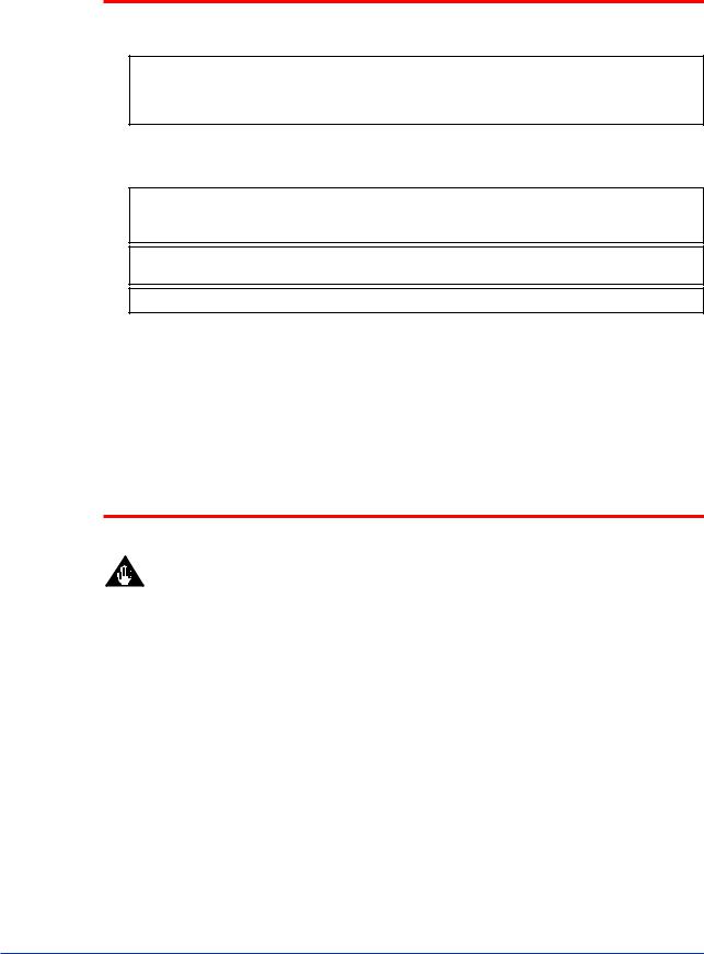
Sampling is carried out by switching a sampling valve. When separating components or detecting concentrations, the sampling valve is set to allow the gas (liquid) to be measured to flow through the sample column. When sampling, the sampling valve leads the gas (liquid) to be measured to a column on a carrier gas. (See Figure1.1)
There are two important points regarding sampling: a regular volume is sampled since repeated sampling is required; and samples are taken quickly and securely. The volume is fixed by measuring a specific gas (liquid) of controlled temperature and pressure using a sample measurement tube. Samples are taken quickly and securely by ensuring that the gas to be measured always flows without interrupt.
Component separation and concentration detection
Measuring tube
Sample valve |
|
Sample |
Vent |
Column |
Detector |
Electric signal
Carrier gas
|
|
|
|
|
|
Status of sampling |
|
|
|
|
||
|
|
|
|
|
|
|
|
|
|
|
||
|
|
|
Measuring tube |
|
|
|
|
|||||
|
|
|
|
|
|
Sample valve |
|
|
|
|
||
|
Sample |
|
|
|
|
|
|
|
|
|
Vent |
|
|
|
|
|
|
Column |
|
|
Detector |
||||
|
|
|
|
|
|
|
|
|
|
|||
|
|
|
|
|
|
|
|
|
|
|
|
|
|
|
|
|
|
|
|
|
|
|
|
|
|
|
|
|
|
|
|
|
|
|
|
|
|
|
|
|
|
|
|
|
|
|
|
|
Electric signal |
||
|
Carrier gas |
|
|
|
|
|
|
|
|
|
|
|
|
|
|
|
|
|
|
|
|
|
|
|
F0101.EPS |
|
|
|
|
|
|
|
|
|
|
|
|
|
Figure 1.1 |
Basic Configuration of Gas Chromatograph |
|||||||||||
IM 11B03A03-01E 3rd Edition : Aug. 23. 2006-00

<Toc> <Ind> |
<1. Principle of Gas Chromatograph > |
1-2 |
1.2Component Separation Using Column
Three types of columns are available for the GC1000 Process Gas Chromatographs: the packed column, the mega-bore column and the capillary column.
The packed column consists of a stainless pipe, 2 mm in diameter and 0.2 to 2.0 m in length and filled with a bulking agent called a stationary phase.
The mega-bore and capillary columns, of approximate diameter 0.5 mm and 0.3 mm respectively, are coated inside a certain phase called a stationary phase.
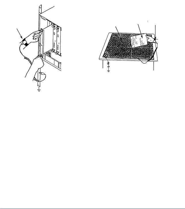
The components in the multi-component gas mixture sample with carrier gas, which called mobil phase move through the column, repeatedly absorbing the stationary phase and dissolving from the stationary phase at a certain cyclic rate conforming to a fixed partition coefficient * that is unique to each component.
Since the transfer rates differ depending on the partition coefficient, a multi-component gas mixture gradually separates into discrete components and is separated in the order of the transfer rates.
* Partition coefficient : The concentration ratio of the components, calculated by dividing the component concentration which is in equilibrium in the stationary phase by the concentration which is in equilibrium in the mobile phase.
Figure 1.2 shows a diagram of how the multi-component gas mixture is led to a column and separated into its discrete components over time.
Multi-component |
:Component A, |
:Component B, |
:Component C |
|
gas mixture |
||||
|
|
|
||
Sampling |
|
|
|
|
(Intake) |
Column |
(Outlet) Detector |
Concentration signal |
Carrier gas
(1st round)
Carrier gas
Injection
Time
A
B
C
(2nd round)
F0102.EPS
Figure 1.2 |
Separating Components Using a Column |
IM 11B03A03-01E 3rd Edition : Aug. 23. 2006-00
<Toc> <Ind> |
<1. Principle of Gas Chromatograph > |
1-3 |
1.3Detector
The components separated in the column are led to the detector where the concentration of each component is measured.
The GC1000 Process Gas Chromatographs can be fitted with thermal conductivity detectors (TCD), flame ionization detectors (FID) or flame photometric detectors (FPD). The thermal conductivity detector can measure almost all non-corrosive components but sensitivity is relatively low. On the other hand, the hydrogen flame ionization detector can measure hydrocarbon and the flame photometric detector can measure sulfur compounds, respectively with high sensitivity.
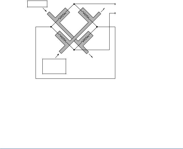
(1)Thermal Conductivity Detector (TCD)
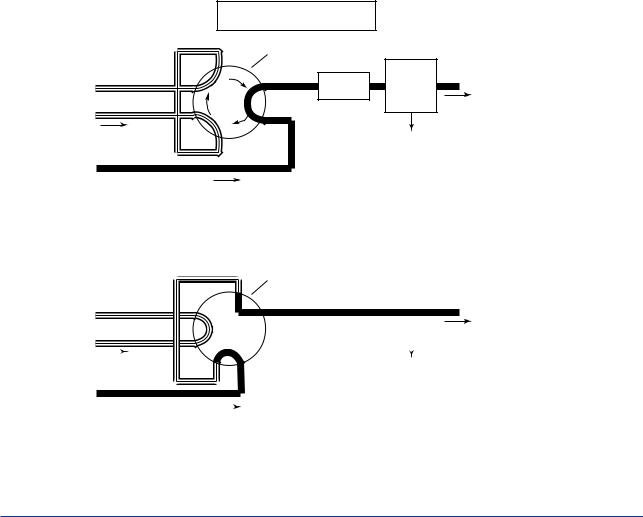
The TCD utilizes the difference in the thermal conductivity between the measured gas and the carrier gas and detects the unbalanced voltage produced in a bridge circuit as a measure of concentration.
Figure 1.3 shows the fundamental principle of the TCD. As shown, there are two streams, each having two filaments. One stream passes the carrier gas only and the other, connected to the column outlet, allows the measured gas to pass during analysis. The filaments in the two streams form a bridge circuit such that the filament in one stream is adjacent to the filament in the other stream. The unbalanced voltage in the bridge is proportional to the concentration of the measured gas (liquid) component.
The TCD is frequently used to measure the component concentration of the measured gas (liquid).
Carrier gas |
Comparison |
Measurment |
|
|
Output |
||
|
filament |
filament |
|
|
|
||
|
Z1 |
Z2 |
|
|
Z4 |
Z3 |
|
Measurment |
Comparison |
|
|
filament |
filament |
|
|
Carrier gas
+
Sampling gas
|
|
Constant voltage |
|
|
|
|
F0103.EPS |
|
|
|
|
Figure 1.3 |
Fundamental Principle ofThermal Conductivity Detector |
||
IM 11B03A03-01E 3rd Edition : Aug. 23. 2006-00
<Toc> <Ind> |
<1. Principle of Gas Chromatograph > |
1-4 |
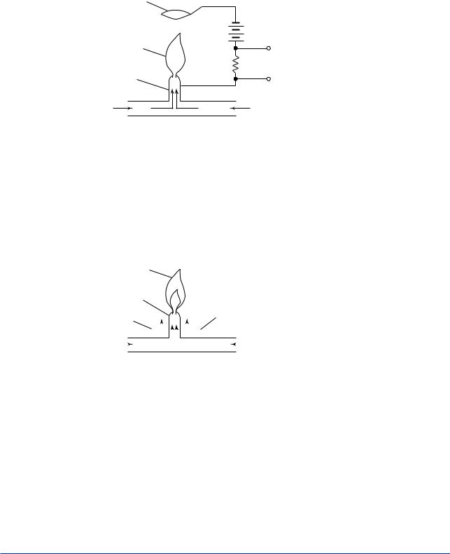
(2)Flame Ionization Detector (FID)
The FID utilizes the phenomenon that carbon molecules in the measured component (hydrocarbon) are ionized in a hot hydrogen flame. That is, it detects the ionization current which flows between electrodes to which a high voltage is applied. The ionization current is proportional to the concentration of the measured component.
The FID is used to measure the component concentration of gases containing low concentrations of hydrocarbons.
Ion collector coil
+
Hydrogen flame
Jet pipe (nozzle)
Carrier gas
+
Sampling gas
- |
- |
+ |
+ |
+ - |
|
+ - |
Output |
Hydrogen gas for combustion
F0104.EPS
Figure 1.4 |
Fundamental Principle of Flame Ionization Detector |
(3)Flame Photometric Detector (FPD)
Figure 1.5 shows the structure of the FPD. As the sample gas containing a sulfur component is led into the excess hydrogen flame, the component containing the sulfur atoms is excited. The FPD detects the luminous intensity of the light emitted when this excited component return to its base state using multiplier phototube and converts it to a voltage. This voltage represents the concentration of the sulfur component in the measured gas.
The FPD can measure on the sulfur component with a high sensitivity of 1 ppm.
Hydrogen flame
|
|
|
|
|
|
|
|
|
|
Photomultiplier tube |
|||||
Jet pipe (nozzle) |
|
|
|
|
|
|
|||||||||
Hydrogen gas |
|
|
|
|
|
|
|
|
|
Hydrogen gas for combustion |
|||||
for combustion |
|
|
|
|
|
|
|
|
|
|
|
|
|
||
|
|
|
|
|
|
|
|
|
|
|
|
|
|||
Carrier gas |
|
|
|
|
|
|
|
|
|
|
|
|
Air fo combustion |
||
+ |
|
|
|
|
|
|
|
|
|
|
|
|
|
|
|
|
|
|
|
|
|
|
|
|
|
||||||
Sampling gas |
|
|
|
|
|
|
|
|
|
|
|
|
F0105.EPS |
||
|
|
|
|
|
|
|
|
|
|
|
|
|
|
|
|
Figure 1.5 |
Basic Configuration of Flame Photometric Detector |
||||||||||||||
IM 11B03A03-01E 3rd Edition : Aug. 23. 2006-00

<Toc> <Ind> |
<2. Terminology > |
2-1 |
2.Terminology
2.1OperationTerminology
Term |
Description |
Notes |
|
|
|
Remote Mode |
Status accessible without password, |
|
|
LCD/key: used only for reference |
|
|
GCMT: connectable |
|
Local Mode |
Status accessible by entering password |
|
|
LCD/key: used for changing settings |
|
Status |
|
|
Process |
Normal measurement and calibration |
|
Manual |
Manual operation |
|
Lab |
Measurement with automatic peak detection, like a lab GC |
|
Operation Mode |
|
|
Run |
Mode in which measurement is running |
|
Pause |
Mode in which measurement pauses |
|
Stop |
Mode in which measurement stops |
|
Measurement Status |
|
|
Stream Sequence |
Continuously measures streams in order specified in Stream Sequence |
|
Stream (continuous) |
Continuously measures the specified stream |
|
Stream (1 cycle) |
Measures the specified stream once |
|
Calibration |
Performs calibration of the specified number |
|
Validation |
Performs validation of the specified number |
|
Method |
Configures action timing of various valves and other parameters |
|
Analysis Cycle |
Time from start (0 second) to stop of analysis |
|
Warming Up Time |
Time for displacement in sample streams |
|
Peak Detection Stop Time |
Time to stop peak detection of chromatogram compulsorily |
|
Pause Time |
Time for measurement pause |
|
Purging |
Displacement of the gas in the pressurized/Type X purged enclosures |
|
|
with a protection gas |
|
|
|
|
|
|
T0201.EPS |
IM 11B03A03-01E 3rd Edition : Aug. 23. 2006-00
<Toc> <Ind> |
<2. Terminology > |
2-2 |
2.2InstrumentTerminology
Term |
Explanation |
Notes |
|
|
|
TCD |
A thermal conductivity detector |
|
FID |
A flame ionization detector |
|
FPD |
A flame photometric detector |
|
LSV |
A liquid sampling valve |
|
Restrictor |
A variable resistor |
|
Methane converter |
A methane reaction system : Methanizer |
|
Sampling valve |
A valve for inputting samples |
|
Back-flush valve |
A switching valve for back flush |
|
Column switching valve |
A valve for switching between columns |
|
Atmospheric-pressure balancing |
A balancing valve for sampling gases |
|
valve |
|
|
Protection gas |
Air |
|
Flame arrester |
A device for protecting against "flame runaway" |
|
Splitter |
A flow splitter |
|
Pressurized enclosure |
An enclosure whose internal pressure is kept high with protection gas |
|
Temperature protection circuit |
A circuit for turning off the heater to prevent overheating |
|
Protection device |
A device for detecting a pressure drop in the analyzer to shut down the |
|
|
power supply |
|
EPC |
Electric pressure controller |
|
|
|
|
|
|
T0202.EPS |
IM 11B03A03-01E 3rd Edition : Aug. 23. 2006-00
<Toc> <Ind> |
<3. Overview > |
3-1 |
3.System Configuration
3.1Type and Appearance
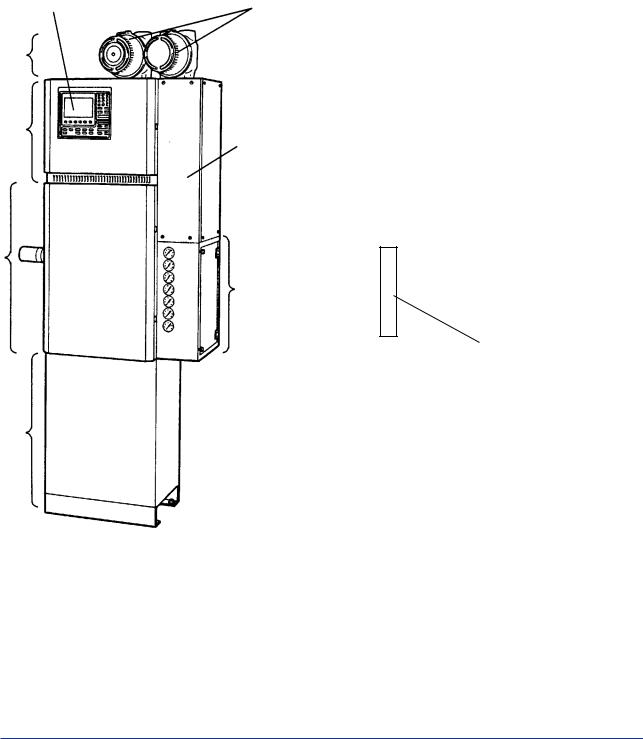
The GC1000 Process Gas Chromatographs consist of (A) a protection system, (B) an electronic section, (C) a pressure and flow control section, (D) an isothermal oven, (E) a programmed-temperature oven (GC1000D / GC1000T / GC1000W) and (F) an analyzer base sampling section (see Figure 3.1).
Note: There are two types of analyzer base sampling section, either the built-in type within GC1000 (the sample processor is embedded), or the external type (the sample processor is separate). Select the type best suited to the intended usage.
Display |
Explosion proof enclosures |
|
(number depends on |
|
specifications) |
(A)Protection system
(B)Electronic section
Terminal section
(D)Isothermal oven
(E)Programmed-temperature oven
(C) Pressure and
flow control section
EPC box
(in the case that EPC is installed)
(F)Analyzer base sampling section
(Note)
F0301.EPS
Figure 3.1Analyzer Components
IM 11B03A03-01E 3rd Edition : Aug. 23. 2006-00

<Toc> <Ind> |
<3. Overview > |
3-2 |
3.2Components andTheir Functions
3.2.1. Protection System
The protection system has a explosion-proof construction and is equipped with a built-in protection circuit. The power relay, pressure switch, timer, relays, override switch, etc. are internal to the instrument. The override function is particularly important for maintenance, since it allows the power to be turned on even if there is an internal pressure loss. The system monitors the internal pressures of the electronic section, isothermal oven and the programmed-temperature oven (GC1000D / GC1000T / GC1000W), and if any of them indicates an internal pressure lower than 392 Pa, it shuts down the power supply to those components. After a power shut-down, when the internal pressure is restored, the system automatically purges over the 12 minutes, then turns on the power again. Analyzers of non- explosion-proof type and with FM/CSA Type Y purging do not have this protection system.
3.2.2Electronic Section
The electronic section has a pressurized protection/Type X purged structure and is designed for control of a detector, an isothermal oven, various valves and others, for processing and computation, and for output of the results. The LCD and operation keys on the front of the electronic section allow manual operation of the GC1000 Mark II.
3.2.3Pressure and Flow Control Section
The pressure and flow control sections control and indicate the pressures of sample gases, standard gases, carrier gases, FID or FPD hydrogen (or nitrogen) for combustion, or FID or FPD air for combustion. Regulator values or EPC is installed. It also contains pressurereducing valves for controlling purge gases, the air for actuating valves or the vortex tube, an air-actuated valve for balancing atmospheric pressure, a vortex tube and a hydrogen restriction system.
3.2.4Isothermal Oven
The isothermal oven has an pressurized protection / Type X purged structure. The temperature is set at a fixed level from 55 to 225°C (setting by 1°C unit). The isothermal oven contains valves such as the sample valve which is air-activated, the back flush valve, the column for separating a multi-component gas mixture into its individual components and leading the components to the detector in sequence, the detector for detecting the components, and the restrictor for controlling the gas flow rate, etc.
There are three types of detector, the thermal conductivity detector (TCD), the flame ionization detector (FID) and the flame photometric detector (FPD); either one or two of these detectors can be used simultaneously (however, the FPD can only be installed in the combustion chamber).
The component signals picked up by the detector are led to the electronic section for signal processing.
IM 11B03A03-01E 3rd Edition : Aug. 23. 2006-00

<Toc> <Ind> |
<3. Overview > |
3-3 |
3.2.5Programmed-temperature Oven
The programmed-temperature oven has an internal pressure protection / Type X purged structure. It contains a column that separates multi-component mixture samples into individual components and leads them to the detector in sequence. The temperature can be set to a fixed setting or it can be programmed. The allowable temperature range is 60 to 320°C without a cooling system, or 5 to 320°C with a cooling system, and the temperature can be set to rise from between 0.1 to 30°C/min (setting by 0.1°C unit). Up to three tem- perature-rise patterns can be programmed.
3.2.6Analyzer Base Sampling Section
The analyzer base sampling section is equipped with sample and standard gas streams, and controls the sample pressure and flow rate. It also selectively sends the sample to be analyzed in a stream, and can switch the standard gas to the isothermal or the pro- grammed-temperature oven by a valve depending on the signal sent from the electronic section.
If the analyzer does not contain the analyzer base sampling section, then samples can be processed externally by supplying air to a separate sampling section.
IM 11B03A03-01E 3rd Edition : Aug. 23. 2006-00
Loading...