


 Loading...
User’s |
|
Manual |
ASIU |
|
Analyzer Server Interface Unit |
|
Software |
IM 11B06F01-01E
IM 11B06F01-01E
4th Edition

i
Introduction
Thank you for purchasing the ASIU Analyzer Server Interface Unit Software.
ASIU Analyzer Server Interface Unit is the software to communicate with DCS and to make the data storage and the maintenance of the field analyzer/sensor on a PC by inputting their information (Analog and Digital) except GC into the I/O unit (FCN) Connected by theANABUS network.
This manual describes the basic method of operating theASIU.
For how to operate GC8000 or GC1000 MarkII, refer to their corresponding user’s manuals.
• Applicatable Readers
The description of the installation method assumes that the reader has a basic knowledge of hardware and software that is necessary for installing the ASIU, and Windows as well.
For further details of Windows, refer to the respective manuals.
• Contents of the Package
The contents of the package are as follows. Check the contents of your package.
•ASIU installation disc
•ASIU User’s Manual (this manual)
Media No. IM 11B06F01-01E |
4th Edition :Nov. 2011 (YK) |
IM 11B06F01-01E 4th Edition : Nov. 22, 2011-00 |
All Rights Reserved Copyright © 2006, Yokogawa Electric Corporation |
|
|

ii
Safety Precautions
•In order to protect the system controlled by the product and the product itself and ensure safe operation, observe the safety precautions described in this user’s manual. We assume no liability for safety if users fail to observe these instructions when operating the product.
•Modification of the product is strictly prohibited.
nNotes on Handling User’s Manuals
•Please hand over the user’s manuals to your end users so that they can keep the user’s manuals on hand for convenient reference.
•Please read theinformation thoroughly before using the product.
•The purpose ofthese user’s manuals is not to warrant that the product is well suited to any particular purpose but rather to describe the functional details of the product.
•No part ofthe user’s manuals may be transferred or reproduced without prior written consent from YOKOGAWA.
•YOKOGAWAreserves the right to make improvements in the user’s manuals and product at any time, without notice or obligation.
•If you haveany questions, or you find mistakes or omissions in the user’s manuals, please contact our sales representative or your local distributor.
nWarning and Disclaimer
The product is provided on an “as is” basis. YOKOGAWAshall have neither liability nor responsibility to any person or entity with respect to any direct or indirect loss or damage arising from using the product or any defect of the product that YOKOGAWAcan not predict in advance.
nNotes on Software
•YOKOGAWAmakes no warranties, either expressed or implied, with respect to the software’s merchantability or suitability for any particular purpose, except as specified in the terms of warranty.
•This product maybe used on a machine only. If you need to use the product on another machine, you must purchase another product.
•It is strictlyprohibited to reproduce the product except for the purpose of backup.
•Store the CD-ROM(the original medium) in a safe place.
•It is strictlyprohibited to perform any reverse-engineering operation, such as reverse compilation or reverse assembling on the product.
•No part ofthe product may be transferred, converted or sublet for use by any third party, without prior written consent from YOKOGAWA.
IM 11B06F01-01E 4th Edition : Nov. 22, 2011-00
iii
Documentation Conventions
n Symbol Marks
Throughout this user’s manual, you will find several different types of symbols are used to identify different sections of text. This section describes these icons.
NOTE
Identifies important information required to understand operations or functions.
TIP
Identifies additional information.
SEE ALSO
Identifies a source to be referred to.
HELP !
Indicates text describing the action to be taken when a message or indication is displayed during an operation.
n Keyboard Inscriptions
Keyboard operations are indicated in this manual as shown in the following example.
(Inscription example) [Shift] + [F1]
(Meaning)
Indicates that the operator must press the [F1] key while pressing the [Shift] key.
n Menu Inscriptions
Menu operations are indicated in this manual as shown in the following example. (Inscription example)
Click on [Connect] in the [System] menu. (Meaning)
Click on the [System] menu, then click on the [Connect] command.
n Drawing Conventions
Some drawings may be partially emphasized, simplified, or omitted, for the convenience of description.
Some screen images depicted in the user’s manual may have different display positions or character types (e.g., the upper / lower case).Also note that some of the images contained in this user’s manual are display examples.
IM 11B06F01-01E 4th Edition : Nov. 22, 2011-00

iv
Copyright and Trademark Notices
n All Rights Reserved
The copyrights of the programs and on-line manual contained in the CD-ROM are reserved.
The on-line manual is protected by the PDF security from modification, however, it can be output via a printer. Printing out the on-line manual is only allowed for the purpose of using the product.
When using the printed information of the on-line manual, check if the version is the most recent one by referring to the CD-ROM’s version.
No part of the on-line manual may be transferred, sold, distributed (including delivery via a commercial PC network or the like), or registered or recorded on video tapes.
nTrademark Acknowledgments
•Microsoft, Windows andWindows NT are either registered trademarks or trademarks of Microsoft Corporation in the United States and/or other countries.
•Ethernet is aregistered trademark of XEROX Corporation.
•Modbus is aregistered trademark of Schneider Electric SA.
•All other companyand product names mentioned in this user’s manual are trademarks or registered trademarks of their respective companies.
•We do not use TM or ® mark to indicate those trademarks or registered trademarks in this user’s manual.
IM 11B06F01-01E 4th Edition : Nov. 22, 2011-00

Toc-1
ASIU
Analyzer Server Interface Unit
Software
|
|
|
IM 11B06F01-01E 4th Edition |
|
CONTENTS |
|
|
||
Introduction............................................................................................................... |
|
|
i |
|
Safety Precautions.................................................................................................. |
|
ii |
||
Documentation Conventions................................................................................ |
iii |
|||
Copyright and Trademark Notices........................................................................ |
iv |
|||
1. |
Outline........................................................................................................ |
|
|
1-1 |
2. |
Configuration............................................................................................ |
|
2-1 |
|
|
2.1 |
Hardware configuration.................................................................................... |
2-1 |
|
|
2.2 |
Software configuration..................................................................................... |
2-1 |
|
3. |
Functions................................................................................................... |
|
3-1 |
|
|
3.1 |
I/O card................................................................................................................ |
|
3-1 |
|
3.2 |
Alarm information.............................................................................................. |
3-2 |
|
|
3.3 |
Modbus interface table..................................................................................... |
3-2 |
|
4. |
Engineering............................................................................................... |
|
4-1 |
|
|
4.1 |
Installation.......................................................................................................... |
4-1 |
|
|
|
4.1.1 |
Preparation......................................................................................... |
4-1 |
|
|
4.1.2 |
Initial setting........................................................................................ |
4-1 |
|
4.2 |
Modification work.............................................................................................. |
4-3 |
|
|
4.3 |
Supplement........................................................................................................ |
4-4 |
|
|
|
4.3.1 |
Modification of IP addressing setting.................................................. |
4-4 |
|
|
4.3.2 |
Modification of serial port setting........................................................ |
4-8 |
5. |
OPC DA 2.0 Interface................................................................................ |
5-1 |
||
|
5.1 |
System Configuration....................................................................................... |
5-1 |
|
|
5.2 |
Software Required............................................................................................. |
5-1 |
|
|
5.3 |
Installation and Settings................................................................................... |
5-1 |
|
|
5.4 |
Update rate......................................................................................................... |
5-1 |
|
|
5.5 |
List of OPC Data Names................................................................................... |
5-2 |
|
Revision Information................................................................................................ |
|
i |
||
IM 11B06F01-01E 4th Edition : Nov. 22, 2011-00
<1. Outline> |
1-1 |
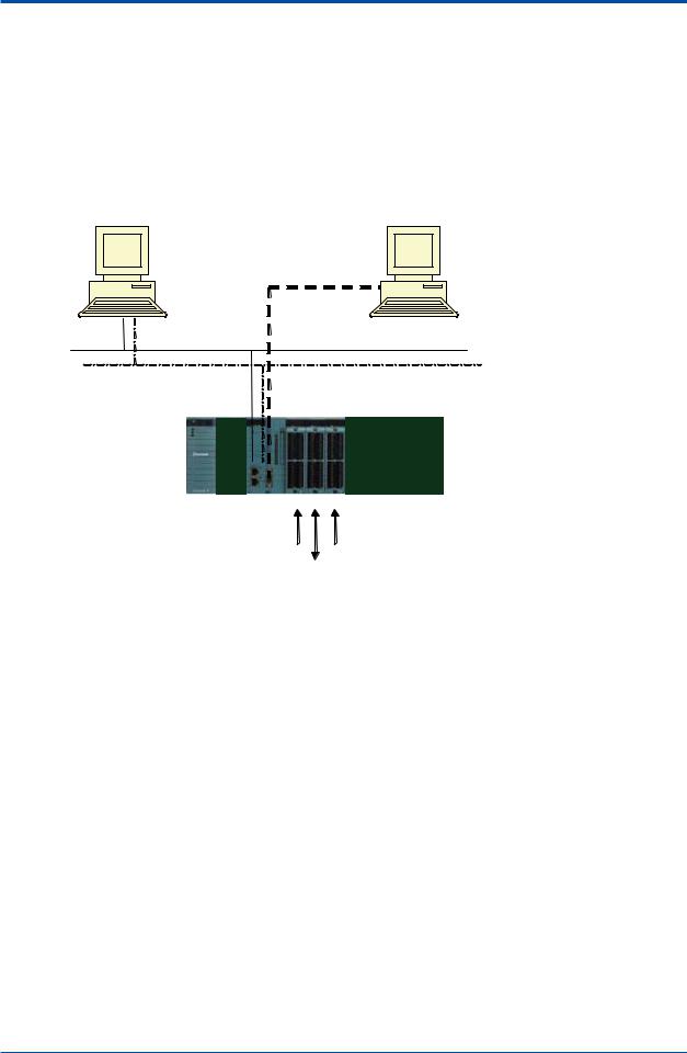
1.Outline
ASIU is a component designed for Ethernet analyzer bus system. It is realized with the I/O unit software on FCN hardware.
ASIU is equipped max. 3 sets of I/O card and transfer I/O information to outside by two type interfaces: Modbus TCP Ethernet one port and Modbus RTU serial.
Modbus mapping is realized with address table and programming is not necessary. FCN is described asASIU is in this document.
Modbus RTU
Serial
Modbus TCP
Ethernet (Redundancy is available)
|
|
Space |
Empty slot |
|
|
|
|
|
|
|
Power |
CPU |
|
|
|
|
DI |
AI |
|
|
|
|
DO |
F0101.ai |
|
|
|
|
|
Figure 1.1 |
System Configuration |
|
|
|
Network : |
Ethernet (Redundancy isavailable. Port-1 is used on the single communication), |
|||
|
Serial (RS-232C) |
|
|
|
Power card: |
Single |
|
|
|
CPU card : |
Single |
|
|
|
DI card : |
1 pc (Read up to 16 points) |
|
||
DO card : |
1 pc (Readand write up to 16 points) |
|
||
AI card : |
1 pc (Read and write up to 16 points) |
|
||
IM 11B06F01-01E 4th Edition : Nov. 22, 2011-00

<2. Configuration> |
2-1 |
2.Configuration
This chapter explains the configuration of the hardware and software of STARDOM FCN required forASIU.
Refer to the General Specifications of STARDOM for details of each item.
2.1Hardware configuration
The following type FCN is required for theASIU.
• Specification Code
Specify these codes when ordering.
Model Name |
Item |
Remarks |
|
|
|
NFBU200-S□□ |
Base module |
|
NFCP100-S0□ |
CPU module |
|
NFPW441-1□ |
Power module |
100 to 120 VAC |
NFPW442-1□ |
Power module |
220 to 240 VAC |
NFPW444-1□ |
Power module |
24 V DC |
NFDV151 |
Digital input module |
32 points, 24 V DC |
NFDV551 |
Digital output module |
32 points, 24 V DC |
NFDR541 |
Relay output module |
16 points, 24 to 110 V DC /100 to 240 VAC |
NFAI135 |
Analog input module |
4 to 20 mA, 8 points, channel isolation |
NFAI143 |
Analog input module |
4 to 20 mA, 16 points, system isolation |
NFDCV01 |
Dummy cover |
Cover for empty I/O module |
NFDCV02 |
Dummy cover |
Cover for empty power module |
2.2Software configuration
ASIU |
|
|
|
|
|
|
|
|
|
|
|
|
|
Model |
|
Suffix Code |
|
Option Code |
Description |
|
|
|
|
|
|
|
|
ASIU |
....................................... |
|
|
|
.................... |
Software Package |
Function |
-A01 |
|
.................... |
Standard |
||
Language |
|
E |
|
.................... |
English |
|
|
|
J |
|
.................... |
Japanese |
|
___ |
|
|
-N |
|
.................... |
Always "-N" |
___ |
|
|
|
N |
.................... |
Always "N" |
|
|
|
|
|
|
|
ASIU requires the license and software shown below.
License Code |
Item |
Remarks |
NT711AJ-LS05A |
FCN/FCJ basic software license |
It is supplied by a system card. |
|
for single CPU without Java |
|
NT8035J-LW11A |
Modbus communication portfolio |
The license number is indicated |
|
license |
on the order ID sheet. |
IM 11B06F01-01E 4th Edition : Nov. 22, 2011-00
Loading...