


Preface
Fundamental safety 1 instructions
SINUMERIK |
System overview |
|
|
|
Description |
SINUMERIK 840D sl type 1B |
|
NCU 7x0.3 PN, NCU 7x0.3B PN |
Application planning |
|
Dimension drawings |
Manual |
|
|
Assembling |
2
3
4
5
6
Connecting |
7 |
|
|
Technical data |
8 |
|
|
Connectable components |
9 |
|
|
Spare Parts/Accessories |
10 |
Appendix
A
Valid for
SINUMERIK 840D sl / 840DE sl control
06/2014
6FC5397-1EP40-5BA1

Legal information
Warning notice system
This manual contains notices you have to observe in order to ensure your personal safety, as well as to prevent damage to property. The notices referring to your personal safety are highlighted in the manual by a safety alert symbol, notices referring only to property damage have no safety alert symbol. These notices shown below are graded according to the degree of danger.
 DANGER
indicates that death or severe personal injury will result if proper precautions are not taken.
 WARNING
indicates that death or severe personal injury may result if proper precautions are not taken.
 CAUTION
indicates that minor personal injury can result if proper precautions are not taken.
NOTICE
indicates that property damage can result if proper precautions are not taken.
If more than one degree of danger is present, the warning notice representing the highest degree of danger will be used. A notice warning ofinjuryto persons with a safety alert symbol may also include a warning relating toproperty damage.
Qualified Personnel
The product/system described in this documentation may be operated only by personnel qualified for the specific taskinaccordancewiththerelevantdocumentation,inparticularitswarningnoticesandsafetyinstructions.Qualified personnel are those who, based on their training and experience, are capable of identifying risks and avoiding potential hazards when working with these products/systems.
Proper use of Siemens products
Note the following:
 WARNING
Siemens products may only be used for the applications described in the catalog and in the relevant technical documentation. If products and components from other manufacturers are used, these must be recommended or approved by Siemens. Proper transport, storage, installation, assembly, commissioning, operation and maintenance are required to ensure that the products operate safely and without any problems. The permissible ambient conditions must be complied with. The information in the relevant documentation must be observed.
Trademarks
All names identified by ® are registered trademarks of Siemens AG. The remaining trademarks in this publication may be trademarks whose use by third parties for their own purposes could violate the rights of the owner.
Disclaimer of Liability
We have reviewed the contents of this publication to ensure consistency with the hardware and software described. Since variance cannot be precluded entirely, we cannot guarantee full consistency. However, the information in this publication is reviewed regularly and any necessary corrections are included in subsequent editions.
Siemens AG |
Order number: 6FC5397-1EP40-5BA1 |
Copyright © Siemens AG 2011 - 2014. |
Industry Sector |
07/2014 Subject to change |
All rights reserved |
Postfach 48 48 |
|
|
90026 NÜRNBERG |
|
|
GERMANY |
|
|
Preface
SINUMERIK documentation
The SINUMERIK documentation is organized in the following categories:
●General documentation
●User documentation
●Manufacturer/service documentation
Additional information
You can find information on the following topics at http://www.siemens.com/motioncontrol/ docu:
●Ordering documentation/overview of documentation
●Additional links to download documents
●Using documentation online (find and search in manuals/information)
Please send any questions about the technical documentation (e.g. suggestions for improvement, corrections) to the following address:
mailto:docu.motioncontrol@siemens.com
My Documentation Manager (MDM)
Under the following link you will find information to individually compile OEM-specific machine
documentation based on the Siemens content:
http://www.siemens.com/mdm
Training
For information about the range of training courses, refer to:
●http://www.siemens.com/sitrain
SITRAIN - Siemens training for products, systems and solutions in automation technology
●http://www.siemens.com/sinutrain SinuTrain - training software for SINUMERIK
FAQs
You can find Frequently Asked Questions in the Service&Support pages under Product
Support.
NCU 7x0.3 PN, NCU 7x0.3B PN |
3 |
Manual, 06/2014, 6FC5397-1EP40-5BA1 |

Preface
http://support.automation.siemens.com
SINUMERIK
You can find information on SINUMERIK under the following link: http://www.siemens.com/sinumerik
Target group
This documentation is intended for manufacturers of machine tools, particularly:
●Project engineers, electricians and installers
●Maintenance and service personnel
Benefits
The information in this manual facilitates installation and connection of the SINUMERIK 840D numerical control in the control cabinet.
Standard scope
This documentation only describes the functionality of the standard version. Extensions or changes made by the machine tool manufacturer are documented by the machine tool manufacturer.
Other functions not described in this documentation might be executable in the controller. This does not, however, represent an obligation to supply such functions with a new controller or when servicing.
Further, for the sake of simplicity, this documentation does not contain all detailed information aboutalltypesoftheproductandcannotcovereveryconceivablecaseofinstallation,operation or maintenance.
Technical Support
You will find telephone numbers for other countries for technical support in the Internet under http://www.siemens.com/automation/service&support
EC Declaration of Conformity
The EC Declaration of Conformity for the EMC Directive can be found on the Internet at: http://support.automation.siemens.com/WW/view/de/10805517/134200
4 |
NCU 7x0.3 PN, NCU 7x0.3B PN |
Manual, 06/2014, 6FC5397-1EP40-5BA1 |
Table of contents
|
Preface |
......................................................................................................................................................... |
3 |
1 |
Fundamental ...................................................................................................................safety instructions |
9 |
|
|
1.1 ............................................................................................................ |
General safety instructions |
9 |
|
1.2 ........................................................................... |
Handling electrostatic sensitive devices (ESD) |
12 |
|
1.3 ........................................................................................................................ |
Industrial security |
12 |
|
1.4 ........................................................................................ |
Residual risks of power drive systems |
13 |
2 |
System ........................................................................................................................................overview |
17 |
|
|
2.1 ................................................................................................................................... |
Application |
17 |
|
2.2 ................................................................................................................... |
System configuration |
17 |
|
2.3 ....................................................................................................................................... |
Variants |
20 |
|
2.4 .............................................................................................................................. |
Ordering data |
21 |
3 |
Description.................................................................................................................................................. |
23 |
|
|
3.1 ............................................................................................................................. |
Characteristics |
23 |
|
3.2 .................................................................................................................................... |
Illustration |
23 |
|
3.3 .................................................................................................................................. |
Type plates |
25 |
|
3.4 ........................................................................................ |
Operator control and display elements |
26 |
|
3.4.1 ............................................................................... |
Overview of operating and display elements |
26 |
|
3.4.2 ............................................................................................................................... |
LED displays |
26 |
|
3.4.3 ....................................................................................................................... |
7 - segment display |
27 |
|
3.4.4 ............................................................................................................................. |
RESET button |
28 |
|
3.4.5 .............................................................................................. |
Start - up and mode selector switch |
29 |
|
3.5 .............................................................................................................. |
Dual fan/battery module |
29 |
4 |
Application ...................................................................................................................................planning |
31 |
|
|
4.1 ................................................................................................... |
Secondary electrical conditions |
31 |
|
4.1.1 ...................................................................................................................... |
Grounding concept |
31 |
|
4.1.2 ............................................................................................................ |
RI suppression measures |
31 |
|
4.2 ..................................................................... |
Climatic and mechanical environmental conditions |
33 |
|
4.2.1 ................................................................................................. |
Shipping and storage conditions |
33 |
|
4.2.2 ................................................................................................................... |
Operating conditions |
35 |
|
4.3 ................................................................................................................ |
Recycling and disposal |
36 |
5 |
Dimension ...................................................................................................................................drawings |
37 |
|
6 |
Assembling................................................................................................................................................. |
39 |
|
|
6.1 ....................................................................................................................... |
Safety information |
39 |
|
6.2 ....................................................................................................................................... |
Designs |
40 |
NCU 7x0.3 PN, NCU 7x0.3B PN |
5 |
Manual, 06/2014, 6FC5397-1EP40-5BA1 |

Table of contents
|
6.3 |
Fix the NCU using spacers.......................................................................................................... |
41 |
|
6.4 |
Mounting the NCU without spacers............................................................................................. |
41 |
|
6.5 |
Mounting the NCU for external cooling....................................................................................... |
42 |
7 |
Connecting................................................................................................................................................. |
45 |
|
|
7.1 |
Overview..................................................................................................................................... |
45 |
|
7.2 |
Safety information for wiring........................................................................................................ |
47 |
|
7.3 |
Opening the front cover............................................................................................................... |
48 |
|
7.4 |
Power supply............................................................................................................................... |
49 |
|
7.4.1 |
Application................................................................................................................................... |
49 |
|
7.4.2 |
Requirements for the power supply............................................................................................. |
50 |
|
7.4.3 |
Connecting the power supply...................................................................................................... |
52 |
|
7.5 |
DRIVE-CLiQ components........................................................................................................... |
52 |
|
7.5.1 |
Application................................................................................................................................... |
52 |
|
7.5.2 |
Connectable DRIVE-CLiQ components...................................................................................... |
54 |
|
7.6 |
Use of Ethernet interfaces........................................................................................................... |
55 |
|
7.7 |
PROFINET.................................................................................................................................. |
58 |
|
7.7.1 |
Application................................................................................................................................... |
58 |
|
7.7.2 |
PROFINET cables....................................................................................................................... |
60 |
|
7.7.3 |
Preparing the twisted pair cables................................................................................................ |
61 |
|
7.7.4 |
Example PROFINET CBA configuration..................................................................................... |
63 |
|
7.8 |
PROFIBUS DP............................................................................................................................ |
64 |
|
7.8.1 |
Application................................................................................................................................... |
64 |
|
7.8.2 |
PROFIBUS cables and connectors............................................................................................. |
66 |
|
7.8.3 |
Connection components in PROFIBUS...................................................................................... |
67 |
|
7.8.4 |
Rules for the laying of PROFIBUS cables................................................................................... |
68 |
|
7.8.5 |
Connecting PROFIBUS DP......................................................................................................... |
68 |
|
7.8.6 |
Disconnecting stations from the PROFIBUS............................................................................... |
69 |
|
7.8.7 |
Operating the X136 interface as MPI.......................................................................................... |
69 |
|
7.9 |
Digital inputs/outputs................................................................................................................... |
71 |
|
7.9.1 |
DIO application............................................................................................................................ |
71 |
|
7.9.2 |
Block diagram.............................................................................................................................. |
74 |
|
7.9.3 |
Connecting digital inputs/outputs................................................................................................ |
75 |
|
7.9.4 |
Technical data............................................................................................................................. |
76 |
|
7.10 |
USB............................................................................................................................................. |
78 |
|
7.11 |
Measuring sockets...................................................................................................................... |
78 |
8 |
Technical data............................................................................................................................................ |
81 |
|
9 |
Connectable components........................................................................................................................... |
83 |
|
|
9.1 |
NX10.3 / NX15.3......................................................................................................................... |
83 |
|
9.1.1 |
Description.................................................................................................................................. |
83 |
|
9.1.2 |
Dimension drawing...................................................................................................................... |
87 |
|
9.1.3 |
Mounting...................................................................................................................................... |
88 |
|
9.1.4 |
Connection.................................................................................................................................. |
90 |
|
9.1.5 |
Technical Data............................................................................................................................ |
94 |
6 |
NCU 7x0.3 PN, NCU 7x0.3B PN |
Manual, 06/2014, 6FC5397-1EP40-5BA1 |

Table of contents
|
9.2 |
PP 72/48D PN ............................................................................................................................. |
95 |
|
9.2.1 |
Description .................................................................................................................................. |
95 |
|
9.2.2 |
Mounting ...................................................................................................................................... |
97 |
|
9.2.3 |
Connecting ................................................................................................................................ |
100 |
|
9.2.3.1 |
Interface overview ..................................................................................................................... |
100 |
|
9.2.3.2 |
X1 power supply ........................................................................................................................ |
100 |
|
9.2.3.3 |
X2 PROFINET ........................................................................................................................... |
103 |
|
9.2.3.4 |
X111, X222 and X333 digital inputs/outputs ............................................................................. |
105 |
|
9.2.4 |
Parameter assignment .............................................................................................................. |
111 |
|
9.2.4.1 |
Input / output images ................................................................................................................. |
111 |
|
9.2.4.2 |
Diagnostics via input image ....................................................................................................... |
112 |
|
9.2.5 |
Technical data ........................................................................................................................... |
113 |
|
9.3 |
PP 72/48D 2/2A PN ................................................................................................................... |
114 |
|
9.3.1 |
Description ................................................................................................................................ |
114 |
|
9.3.2 |
Dimension drawing .................................................................................................................... |
117 |
|
9.3.3 |
Mounting .................................................................................................................................... |
117 |
|
9.3.4 |
Connection ................................................................................................................................ |
118 |
|
9.3.4.1 |
Interface overview ..................................................................................................................... |
118 |
|
9.3.4.2 |
X1 power supply ........................................................................................................................ |
119 |
|
9.3.4.3 |
X2 PROFINET ........................................................................................................................... |
121 |
|
9.3.4.4 |
X111, X222 and X333 digital inputs/outputs ............................................................................. |
124 |
|
9.3.4.5 |
Analog X3 inputs/outputs .......................................................................................................... |
130 |
|
9.3.5 |
Parameter assignment .............................................................................................................. |
134 |
|
9.3.5.1 |
Input / output images ................................................................................................................. |
134 |
|
9.3.5.2 |
Assigning parameters to the analog inputs / outputs ................................................................ |
136 |
|
9.3.5.3 |
Analog value representation ...................................................................................................... |
138 |
|
9.3.5.4 |
Examples ................................................................................................................................... |
141 |
|
9.3.5.5 |
Diagnostics via input image ....................................................................................................... |
142 |
|
9.3.6 |
Technical data ........................................................................................................................... |
144 |
|
9.4 |
COM01.3 RS 232C (V.24) module ............................................................................................ |
145 |
|
9.4.1 |
Description ................................................................................................................................ |
145 |
|
9.4.2 |
Installation/Mounting ................................................................................................................. |
147 |
|
9.4.3 |
Connection ................................................................................................................................ |
147 |
|
9.5 |
CBE30 - 2 .................................................................................................................................... |
148 |
|
9.5.1 |
Description ................................................................................................................................ |
148 |
|
9.5.2 |
Installation/Mounting ................................................................................................................. |
151 |
|
9.5.3 |
Connection ................................................................................................................................ |
152 |
10 |
Spare Parts/Accessories.......................................................................................................................... |
155 |
|
|
10.1 |
Replacing the dual fan/ battery module ..................................................................................... |
155 |
|
10.2 |
CompactFlash Card .................................................................................................................. |
157 |
|
10.2.1 |
Properties of the CompactFlash card ........................................................................................ |
157 |
|
10.2.2 |
Inserting the CompactFlash card .............................................................................................. |
157 |
A |
Appendix |
................................................................................................................................................... |
159 |
|
A.1 ............................................................................................................................. |
Abbreviations |
159 |
|
A.2 ........................................................................................................... |
Documentation overview |
161 |
|
Index......................................................................................................................................................... |
|
163 |
NCU 7x0.3 PN, NCU 7x0.3B PN |
7 |
Manual, 06/2014, 6FC5397-1EP40-5BA1 |
Fundamental safety instructions |
1 |
|
1.1General safety instructions
 DANGER
Danger to life due to live parts and other energy sources
Death or serious injury can result when live parts are touched.
●Only work on electrical devices when you are qualified for this job.
●Always observe the country-specific safety rules.
Generally, six steps apply when establishing safety:
1.Prepare for shutdown and notify all those who will be affected by the procedure.
2.Disconnect the machine from the supply.
–Switch off the machine.
–Wait until the discharge time specified on the warning labels has elapsed.
–Check that it really is in a no-voltage condition, from phase conductor to phase conductor and phase conductor to protective conductor.
–Check whether the existing auxiliary supply circuits are de-energized.
–Ensure that the motors cannot move.
3.Identify all other dangerous energy sources, e.g. compressed air, hydraulic systems, or water.
4.Isolateorneutralizeallhazardousenergysourcesbyclosingswitches,groundingorshortcircuiting or closing valves, for example.
5.Secure the energy sources against switching on again.
6.Ensure that the correct machine is completely interlocked.
After you have completed the work, restore the operational readiness in the inverse sequence.
 WARNING
Danger to life through a hazardous voltage when connecting an unsuitable power supply Touching live components can result in death or severe injury.
●Only use power supplies that provide SELV (Safety Extra Low Voltage) or PELV- (Protective Extra Low Voltage) output voltages for all connections and terminals of the electronics modules.
NCU 7x0.3 PN, NCU 7x0.3B PN |
9 |
Manual, 06/2014, 6FC5397-1EP40-5BA1 |
Fundamental safety instructions
1.1 General safety instructions
 WARNING
Danger to life when live parts are touched on damaged devices Improper handling of devices can cause damage.
For damaged devices, hazardous voltages can be present at the enclosure or at exposed components; if touched, this can result in death or severe injury.
●Ensure compliance with the limit values specified in the technical data during transport, storage and operation.
●Do not use any damaged devices.
 WARNING
Danger to life through electric shock due to unconnected cable shields
Hazardous touch voltages can occur through capacitive cross-coupling due to unconnected cable shields.
●As a minimum, connect cable shields and the cores of cables that are not used at one end at the grounded housing potential.
 WARNING
Danger to life due to electric shock when not grounded
For missing or incorrectly implemented protective conductor connection for devices with protectionclassI,highvoltagescanbepresentatopen,exposedparts,whichwhentouched, can result in death or severe injury.
● Ground the device in compliance with the applicable regulations.
 WARNING
Danger to life due to fire spreading if housing is inadequate
Fire and smoke development can cause severe personal injury or material damage.
●Installdeviceswithoutaprotectivehousinginametalcontrolcabinet(orprotectthedevice by another equivalent measure) in such a way that contact with fire is prevented.
●Ensure that smoke can only escape via controlled and monitored paths.
10 |
NCU 7x0.3 PN, NCU 7x0.3B PN |
Manual, 06/2014, 6FC5397-1EP40-5BA1 |
Fundamental safety instructions
1.1 General safety instructions
 WARNING
Danger to life through unexpected movement of machines when using mobile wireless devices or mobile phones
Using mobile wireless devices or mobile phones with a transmit power > 1 W closer than approx.2mtothecomponentsmaycausethedevicestomalfunction,influencethefunctional safety of machines therefore putting people at risk or causing material damage.
●Switch the wireless devices or mobile phones off in the immediate vicinity of the components.
 WARNING
Danger to life due to fire if overheating occurs because of insufficient ventilation clearances
Inadequate ventilation clearances can cause overheating of components with subsequent fire and smoke. This can cause severe injury or even death. This can also result in increased downtime and reduced service lives for devices/systems.
●Ensure compliance with the specified minimum clearance as ventilation clearance for the respective component.
 WARNING
Danger to life when safety functions are inactive
Safety functions that are inactive or that have not been adjusted accordingly can cause operational faults on machines that could lead to serious injury or death.
●Observe the information in the appropriate product documentation before commissioning.
●Carryoutasafetyinspectionforfunctionsrelevanttosafetyontheentiresystem,including all safety-related components.
●Ensure that the safety functions used in your drives and automation tasks are adjusted and activated through appropriate parameterizing.
●Perform a function test.
●Only put your plant into live operation once you have guaranteed that the functions relevant to safety are running correctly.
Note
Important safety notices for Safety Integrated functions
If you want to use Safety Integrated functions, you must observe the safety notices in the Safety Integrated manuals.
NCU 7x0.3 PN, NCU 7x0.3B PN |
11 |
Manual, 06/2014, 6FC5397-1EP40-5BA1 |

Fundamental safety instructions
1.3 Industrial security
1.2Handling electrostatic sensitive devices (ESD)
Electrostatic sensitive devices (ESD) are individual components, integrated circuits, modules or devices that may be damaged by either electric fields or electrostatic discharge.
NOTICE
Damage through electric fields or electrostatic discharge
Electric fields or electrostatic discharge can cause malfunctions through damaged individual components, integrated circuits, modules or devices.
●Only pack, store, transport and send electronic components, modules or devices in their original packaging or in other suitable materials, e.g conductive foam rubber of aluminum foil.
●Only touch components, modules and devices when you are grounded by one of the following methods:
–Wearing an ESD wrist strap
–Wearing ESD shoes or ESD grounding straps in ESD areas with conductive flooring
●Onlyplaceelectroniccomponents,modulesordevicesonconductivesurfaces(tablewith
ESD surface, conductive ESD foam, ESD packaging, ESD transport container).
1.3Industrial security
Note
Industrial security
Siemens provides products and solutions with industrial security functions that support the secure operation of plants, solutions, machines, equipment and/or networks. They are important components in a holistic industrial security concept. With this in mind, Siemens’ products and solutions undergo continuous development. Siemens recommends strongly that you regularly check for product updates.
For the secure operation of Siemens products and solutions, it is necessary to take suitable preventive action (e.g. cell protection concept) and integrate each component into a holistic, state-of-the-art industrial security concept. Third-party products that may be in use should also be considered. For more information about industrial security, visit Hotspot-Text (http:// www.siemens.com/industrialsecurity).
To stay informed about product updates as they occur, sign up for a product-specific newsletter. For more information, visit Hotspot-Text (http:// support.automation.siemens.com).
12 |
NCU 7x0.3 PN, NCU 7x0.3B PN |
Manual, 06/2014, 6FC5397-1EP40-5BA1 |

Fundamental safety instructions
1.4 Residual risks of power drive systems
 WARNING
Danger as a result of unsafe operating states resulting from software manipulation
Software manipulation (e.g. by viruses, Trojan horses, malware, worms) can cause unsafe operating states to develop in your installation which can result in death, severe injuries and/ or material damage.
●Keep the software up to date.
You will find relevant information and newsletters at this address (http:// support.automation.siemens.com).
●Incorporatetheautomationanddrivecomponentsintoaholistic,state-of-the-artindustrial security concept for the installation or machine.
You will find further information at this address (http://www.siemens.com/ industrialsecurity).
●Makesurethatyouincludeallinstalledproductsintotheholisticindustrialsecurityconcept.
1.4Residual risks of power drive systems
Thecontrolanddrivecomponentsofadrivesystemareapprovedforindustrialandcommercial useinindustriallinesupplies.Theiruseinpubliclinesuppliesrequiresadifferentconfiguration and/or additional measures.
Thesecomponentsmayonlybeoperatedinclosedhousingsorinhigher-levelcontrolcabinets with protective covers that are closed, and when all of the protective devices are used.
These components may only be handled by qualified and trained technical personnel who are knowledgeable and observe all of the safety instructions on the components and in the associated technical user documentation.
When assessing the machine's risk in accordance with the respective local regulations (e.g., EC Machinery Directive), the machine manufacturer must take into account the following residual risks emanating from the control and drive components of a drive system:
NCU 7x0.3 PN, NCU 7x0.3B PN |
13 |
Manual, 06/2014, 6FC5397-1EP40-5BA1 |

Fundamental safety instructions
1.4Residual risks of power drive systems
1.Unintentionalmovementsofdrivenmachinecomponentsduringcommissioning,operation, maintenance, and repairs caused by, for example,
–Hardware and/or software errors in the sensors, control system, actuators, and cables and connections
–Response times of the control system and of the drive
–Operation and/or environmental conditions outside the specification
–Condensation/conductive contamination
–Parameterization, programming, cabling, and installation errors
–Use of wireless devices/mobile phones in the immediate vicinity of the control system
–External influences/damage
2.In the event of a fault, exceptionally high temperatures, including an open fire, as well as emissions of light, noise, particles, gases, etc. can occur inside and outside the inverter, e.g.:
–Component failure
–Software errors
–Operation and/or environmental conditions outside the specification
–External influences/damage
Inverters of the Open Type/IP20 degree of protection must be installed in a metal control cabinet (or protected by another equivalent measure) such that contact with fire inside and outside the inverter is not possible.
3.Hazardous shock voltages caused by, for example,
–Component failure
–Influence during electrostatic charging
–Induction of voltages in moving motors
–Operation and/or environmental conditions outside the specification
–Condensation/conductive contamination
–External influences/damage
4.Electrical, magnetic and electromagnetic fields generated in operation that can pose a risk to people with a pacemaker, implants or metal replacement joints, etc., if they are too close
5.Release of environmental pollutants or emissions as a result of improper operation of the system and/or failure to dispose of components safely and correctly
Note
Thecomponentsmustbeprotectedagainstconductivecontamination(e.g.byinstallingthem in a control cabinet with degree of protection IP54 according to IEC 60529 or NEMA 12).
Assuming that conductive contamination at the installation site can definitely be excluded, a lower degree of cabinet protection may be permitted.
14 |
NCU 7x0.3 PN, NCU 7x0.3B PN |
Manual, 06/2014, 6FC5397-1EP40-5BA1 |

Fundamental safety instructions
1.4 Residual risks of power drive systems
Formoreinformationaboutresidualrisksofthecomponentsinadrivesystem,seetherelevant sections in the technical user documentation.
NCU 7x0.3 PN, NCU 7x0.3B PN |
15 |
Manual, 06/2014, 6FC5397-1EP40-5BA1 |
System overview |
2 |
|
2.1Application
Overview
SINUMERIK 840D sl offers modularity, openness, flexibility and uniform structures for operation, programming, and visualization. It provides a system platform with trend-setting functions for almost all technologies.
Integrated into the SINAMICS S120 drive system and complemented by the SIMATIC S7-300 automation system, the SINUMERIK 840D sl forms a complete digital system that is ideally suited for the mid to upper performance range.
SINUMERIK 840D sl is characterized by:
●A high degree of flexibility
●Excellent dynamic response and precision
●Optimum integration into networks
Benefits
●Outstandingperformanceandflexibilityformulti-axissystemsofaveragetohighcomplexity thanks to scalable hardware and software.
●Universal openness of the user interface, the PLC and the NC kernel to allow integration of your specialist know-how.
●Integrated safety functions for man and machine: SINUMERIK Safety Integrated.
●Comprehensive range of products for integrating machine tools into communication, engineering and production processes: SINUMERIK Integrate
Fields of application
The SINUMERIK 840D sl can be used worldwide for turning, drilling, milling, grinding, laser machining, nibbling, punching, in tool and mold making, for high-speed cutting applications, for wood and glass processing, for handling operations, in transfer lines and rotary indexing machines, for mass production and JobShop production.
The SINUMERIK 840DE sl is available as an export version for use in countries requiring an export authorization.
2.2System configuration
SINUMERIK840DslcombinesCNC,HMI,PLC,closed-loopcontrol,andcommunicationtasks within a single NCU (Numerical Control Unit).
NCU 7x0.3 PN, NCU 7x0.3B PN |
17 |
Manual, 06/2014, 6FC5397-1EP40-5BA1 |

System overview
2.2 System configuration
Components
Foroperation,programming,andvisualizationpurposes,thecorrespondingoperatingsoftware is already integrated into the CNC software for the NCU and therefore runs on the highperformance NCU multi-processor module. For increased performance in the operating area, the SINUMERIK PCU 50.5 can be used.
Up to 4 distributed OPs can be operated on one NCU / PCU. The operator panel can be installed as a Thin Client at a distance of up to 100 m.
The following components can be connected to the NCU:
●SINUMERIK operator panel front with TCU x0.2 / PCU 50.5 and Machine Control Panel/ Machine Push Button Panel
●SIMATIC Thin Client (from firmware V2.0.1)
●SIMATIC CE panel
●SINUMERIK handheld units
●Distributed PLC I/O
–via PROFIBUS DP:
e.g. SINUMERIK I/O modules PP 72/48D and Analog Drive Interface for 4 axes ADI 4
–via PROFINET IO:
SINUMERIK I/O modules PP 72/48D PN and PP 72/48D 2/2A PN
●SINAMICS 120 drive system
●Feed and main spindle motors
–Synchronous motors 1FT / 1FK / 1FE1 / 2SP1
–1PH / 1PM induction motors
–Linear / torque motors 1FN / 1FW6
PROFIBUS |
|
PROFIBUSI/OforthePLC/NCKI/O(isochronous) |
x |
NCK/PLCisochronousdrives(e.g.ADI4,CU320) |
x |
PROFIsafe V2 at both interfaces |
x |
Second DP/MPI isochronous interface available |
x |
for NCK |
|
|
|
PROFINET |
|
PROFINET I/O for PLC peripherals |
x |
PROFINET I/O for NCK peripherals (isochronous) |
x |
PLC isochronous drives |
x |
NCK isochronous drives (also with Safety |
x 1) |
Integrated) |
|
18 |
NCU 7x0.3 PN, NCU 7x0.3B PN |
Manual, 06/2014, 6FC5397-1EP40-5BA1 |
System overview
2.2 System configuration
PROFINET |
|
PROFIsafe V2 |
x |
PROFINET CBA |
x 2) |
Requirements: Step7 V5.5
1)Cannot be operated for NCU-Link
2)We recommend changing over from CBA to I-Device
Note
A specific software release is required. More detailed information is available in the corresponding ProdIS for the particular software release.
+7 |
2S U WRU S Q O IURQWV ZLW 7&8 [ |
3&8 |
1&8 |
|
|
|
|
|
|
|
|
1; |
|
|
|
|
|
|
|
|
|
|
|
|
|
|||
|
|
|
|
|
|
|
|
|
|
|
|
|
|
|
|
|
|
|
|
6,1$0,&6 6 |
|
|
|
|
|
3RZ U VXSSO\ |
&8$ |
|
|
|||||||
|
||||||||||
|
|
|
|
|||||||
|
|
|
|
|
|
|
|
|
|
|
|
|
|
|
|
|
6,1$0,&6 6 |
|
|
||
|
|
|
|
|
|
|
|
|||
|
|
|
|
|
|
|
|
|||
|
|
|
|
|
|
|
|
%RRNVL] |
||
,Q XVWUL O (W UQ W 
352),%86 , 2  352),1(7 , 2
'5,9( & L4 
6,1$0,&66& VVLV
6 UYRPRWRUV |
6 UYRPRWRUV |
0 LQ VSLQ O PRWRU |
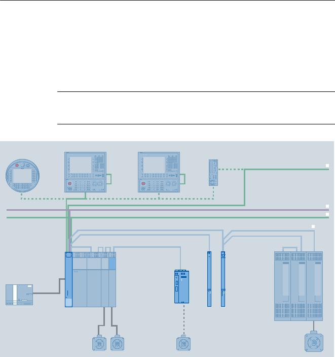
Figure 2-1 Typical topology of the SINUMERIK 840D sl complete system
NCU 7x0.3 PN, NCU 7x0.3B PN |
19 |
Manual, 06/2014, 6FC5397-1EP40-5BA1 |

System overview
2.3 Variants
2SHU WRU S QHO IURQW ZLW 7&8 [


 3&8 +7


,QGXVWUL O (W HUQHW 
33 ' 31
33b 'b $b31
|
|
|
|
|
|
|
|
|
|
|
|
|
|
|
|
|
|
|
|
|
6,0$7,& |
|
|
|
|
|
|
|||||
|
|
352),%86 |
|
|
|
|
|
|
|
|
|
|
|
|
(7 SUR |
|
|
|
|
|
|
|||||||||||
|
|
|
|
|
|
|
|
|
|
|
|
|
|
|
|
|
|
|
|
|
|
|
|
|
|
|||||||
|
|
|
|
|
|
|
|
|
|
|
|
|
|
|
|
|
|
|
|
|
|
|
|
|
|
|
|
|
|
|
|
|
|
|
352),1(7 |
|
|
|
|
|
|
|
|
|
|
|
|
|
|
|
|
|
|
|
|
|
|
|
|
||||||
|
|
|
|
|
|
|
|
|
|
|
|
|
|
|
|
|
|
|
|
|
|
|
||||||||||
|
|
|
|
|
|
|
|
|
|
|
|
|
|
|
'5,9( &/L4 |
|
|
|
6,1$0,&6 6 |
|
|
|
|
|
|
6,1$0,&6 6 |
|
|
|
|||
|
|
|
|
|
|
|
|
|
|
|
|
|
|
|
|
|
|
|
|
|
|
|
|
|
|
|
||||||
|
|
|
|
|
|
|
|
|
|
|
|
|
|
|
|
|
|
|
|
|
|
|
|
|
|
|
||||||
|
|
|
|
|
|
|
|
|
|
|
|
|
1&8 31 |
|
|
|
|
|
|
|
|
|
|
|
||||||||
|
|
|
|
|
|
|
|
|
|
|
|
|
|
|
|
|
|
|
|
|
|
|
|
|||||||||
|
|
|
|
|
|
|
|
|
|
|
|
|
|
|
|
|
|
|
&RP L |
|
|
|
|
|
0RWRU 0RGXOH IRUP W |
|||||||
|
|
|
|
|
|
|
|
3RZHU VXSSO\ |
|
|
|
|
|
|
|
|
|
|
|
|
|
|
%RRNVL]H &RPS FW |
|||||||||
|
|
|
|
|
|
|
|
|
|
|
|
|
|
|
|
|
|
|
|
|
|
|||||||||||
|
|
|
|
|
|
|
|
|
|
|
|
|
|
|
|
|
|
|
|
|
|
|
|
|
|
|
|
|
|
|
|
|
|
|
|
|
|
|
|
|
|
|
|
|
|
|
|
|
|
|
|
|
|
|
|
|
|
|
|
|
|
|
|
|
|
|
|
|
|
|
|
|
|
|
|
|
|
|
|
|
|
|
|
|
|
|
|
|
|
|
|
|
|
|
|
|
|
|
|
|
|
|
|
|
|
|
|
|
|
|
|
|
|
|
|
|
|
|
|
|
|
|
|
|
|
|
|
|
|
|
|
|
|
|
|
|
|
|
|
|
|
|
|
|
|
|
|
|
|
|
|
|
|
|
|
|
|
|
|
|
|
|
|
|
6SLQGOH PRWRU |
|
|
)HHG |
)HHG |
|
|
|||
|
|
PRWRUV |
PRWRUV |
|
3+ |
). |
). |
||
Figure 2-2 Sample topology which is only possible with an NCU 710.3 PN
Networking
The SINUMERIK 840D sl offers integrated PROFINET functionality. Supported:
●PROFINET CBA
The CBA functionality integrated in the NCU allows users to modularize machinery and systems: Rapid real-time communication (up to 10 ms) between the controllers means that systems lend themselves better to standardization and can be reused or expanded more easily. Response to customer demands is faster and more flexible and startup is simplified and speeded up by pretesting at component level.
●PROFINET IO
AspartofPROFINET,PROFINETIOisacommunicationconceptthatisusedtoimplement modular, distributed applications. PROFINET IO is based on Industrial Ethernet and allows distributed field and I/O equipment to be connected to the central processing unit.
128 PROFINET IO devices can be operated on the NCU as an IO controller.
2.3Variants
The scalability of the hardware and software – both from a CNC perspective and in terms of operation – means the SINUMERIK 840D sl can be used in many sectors. The possibilities range from simple positioning tasks up to complex multi-axis systems.
20 |
NCU 7x0.3 PN, NCU 7x0.3B PN |
Manual, 06/2014, 6FC5397-1EP40-5BA1 |
System overview
2.4 Ordering data
Application areas and performance
●Up to 8 axes may be implemented on an NCU 710. The NCU 710 can be expanded by up to 2 NX modules. One possible benefit would be increased drive control performance.
●On the NCU 720/730, the number of axes and/or the performance of the drive controller can be increased to 31 axes. This is achieved through the use of the NX modules. The NCU 720/730 can be expanded by up to 5 NX modules for increased performance of the drive control and number of axes.
●Use of an NCU 730 is recommended for maximum dynamics and accuracy in mold making or in the high speed cutting sector.
The following table shows the key features of the various NCU versions:
Table 2-1 Versions of the NCU
|
NCU 710.3 PN |
NCU 720.3 PN |
|
NCU 720.3B PN |
|
NCU 710.3B PN |
NCU 730.3 PN |
|
NCU 730.3B PN |
Cooling ribs |
No |
Yes |
|
No |
DRIVE CLiQ ports |
4 |
|
6 |
|
Axes |
Up to 8 *) |
|
Up to 31 |
|
NX10.3 / 15.3 |
Up to 2 |
|
Up to 5 |
|
TCU |
Up to 2 |
|
Up to 4 |
|
* ) With SINAMICS S120 Combi, up to 6 axes can be controlled.
2.4Ordering data
Table 2-2 |
Order data for system components |
|
|
|
|
System components |
Order numbers |
|
NCU 710.3 PN with PLC 317-3 DP/PN |
6FC5371-0AA30-0AA1 |
|
NCU 710.3B PN with PLC 317-3 DP/PN |
6FC5371-0AA30-0AB0 |
|
NCU 720.3 PN with PLC 317-3 DP/PN |
6FC5372-0AA30-0AA1 |
|
NCU 720.3B PN with PLC 317-3 DP/PN |
6FC5372-0AA30-0AB0 |
|
NCU 730.3 PN with PLC 317-3 DP/PN |
6FC5373-0AA30-0AA1 |
|
NCU 730.3B PN with PLC 317-3 DP/PN |
6FC5373-0AA30-0AB0 |
|
NCU 730.3B PN with PLC 319-3 DP/PN |
6FC5373-0AA31-0AB0 |
|
Numeric Control Extension NX15.3 (High Extension) |
6SL3040-1NB00-0AA0 |
|
Numeric Control Extension NX10.3 (Standard Extension) |
6SL3040-1NC00-0AA0 |
|
COM01.3RS232C(V.24)moduleforNCU7x0.3PN(cannotbeusedwith |
6FC5312-0FA01-1AA0 |
|
NCU 730.3B PN with PLC 319 DP/PN) |
|
|
CBE30-2 Link module (cannot be used with NCU 730.3B PN with PLC |
6FC5312-0FA00-2AA0 |
|
319 DP/PN) |
|
|
PP 72/48D 2/2A PN I/O module |
6FC5311-0AA00-0AA0 |
|
Terminal Module Compact TMC 2040 PN |
6AU1102-0AB00-0AA0 |
|
Strain relief/ shield connection for I/O cable |
6AU1100-1AB00-0AA0 |
|
NCU 7x0.3 PN, NCU 7x0.3B PN |
21 |
Manual, 06/2014, 6FC5397-1EP40-5BA1 |

System overview
2.4 Ordering data
System components |
Order numbers |
|
5x connectors with screw connection (10 pin) |
6AU1100-0AA00-0AA0 |
|
PP 72/48D 2/2A PN 2/2A PN I/O module |
6FC5311-0AA00-1AA0 |
|
TS Adapter IE ISDN with integrated ISDN terminal adapter |
6ES7972-0ED00-0XA0 |
|
TS Adapter IE Modem with integrated analog modem |
6ES7972-0EM00-0XA0 |
|
USB FlashDrive 8 GB, USB 2.0 |
6ES7648-0DC50-0AA0 |
|
Table 2-3 |
Ordering data for spare parts / accessories |
|
|
|
|
Spare parts / accessories |
Order numbers |
|
Dual fan/battery module |
6FC5348-0AA02-0AA0 |
|
Battery |
|
6FC5247 0AA18 0AA0 |
Seal for segregated heat removal |
6FC5348-0AA07-0AA0 |
|
Spacer for NCU 720.3 PN and NCU 730.3 PN |
6FC5348-0AA06-0AA0 |
|
Spacer for NCU 710.3 PN, NCU 7x0.3B PN |
6SL3064-1BB00-0AA0 |
|
Front cover |
|
6FC5348-0AA30-0AA0 |
Blanking plate for BOP |
6SL3064-3BB00-0AA0 |
|
Cover for optional guide frame |
6SL3064-3CB00-0AA0 |
|
Dust protection, blanking plug (50 pcs.) for DRIVE-CLiQ interfaces |
6SL3066-4CA00-0AA0 |
|
PROFIBUS/MPI plug connector with terminating resistor |
6ES7972-0BB42-0XA0 |
|
PROFIBUS adapter connector to raise the connector |
6FX2003-0BB00 |
|
Terminalkit,consistingofconnectorsX122/X124/X132/X142anddust |
6SL3064-2CB00-0AA0 |
|
cover, blanking plugs for DRIVE-CLiQ interfaces |
|
|
Table 2-4 |
Ordering data of the memory expansion options |
|
|
|
|
Memory expansion options |
Order numbers |
|
CNC user memory expansion 2 MB |
6FC5800 0AD00 0YB0 |
|
PLC user memory expansion 128 KB |
6FC5800 0AD10 0YB0 |
|
Ordering options
The described products can be found in the following catalogs:
●You can find all of the devices that belong to the SINUMERIK 840D sl type 1B and
SINAMICS S120 product families in Catalog NC 62.
●You can find SIMATIC products, which can be connected to the NCU, in Catalogs PM 10 and ST 80.
You can also order the products online:
●Industry Mall: http://www.siemens.com/industrymall
●Spares On Web: http://workplace.automation.siemens.de/sparesonweb
22 |
NCU 7x0.3 PN, NCU 7x0.3B PN |
Manual, 06/2014, 6FC5397-1EP40-5BA1 |
Description |
3 |
|
3.1Characteristics
The following elements designate an NCU:
●Battery-backed real-time clock
●Slot for a CompactFlash Card (behind the blanking cover)
●DRIVE-CLiQ interfaces for connecting to the drive
●Interfaces for operation behind a hinged front cover:
–Ethernet ports
–PROFINET interfaces
–PROFIBUS interfaces
–Digital inputs/outputs (6 of which can be parameterized as inputs for probe and BERO)
●Commissioning interfaces:
–Ethernet interface
–Measuring sockets
3.2Illustration
The following diagram shows an NCU 730.3 PN with its interfaces and control and display elements (fault displays and status indicators). Please ensure that the structure of the NCUs is virtually identical. There are only a few discrepancies, as follows:
●NCU 710.3 PN and NCU 710.3B PN have 4 instead of 6 DRIVE-CliQ interfaces.
●NCU 710.3 PN and all .3B versions do not have any cooling ribs and therefore a different spacer.
NCU 7x0.3 PN, NCU 7x0.3B PN |
23 |
Manual, 06/2014, 6FC5397-1EP40-5BA1 |

Description
3.2 Illustration
; ; '5,9( &/L4 LQWHUI FHV
6KLHOG VXSSRUW
; ; ; 'LJLW O LQSXWV RXWSXWV
; (OHFWURQLFV SRZHU VXSSO\
; 3 3 352),1(7 ,2 LQWHUI FH
; 3 31 ,( 23 (WKHUQHW LQWHUI FH
; 352),%86 '3 LQWHUI FH
; OHIW ; ULJKW[ 86% LQWHUI FH
0$& GGUHVVHV
; b3 31 ,(
(WKHUQHW LQWHUI FH
;
6ORW IRU &RPS FW)O VK & UG
'L JQRVWLFV XWWRQ 3RWHQWL O FRQQHFWLRQ
; XQGHUVLGH 56 QR IXQFWLRQ
6S FHU
&RROLQJ UL V
2SWLRQ VORW FRYHUHG
; 352),%86 '3 03, LQWHUI FH
; 3 31 ,( 1(7 (WKHUQHW LQWHUI FH
7\SH SO WH /(' GLVSO \V
VHJPHQW GLVSO \
5HVHW XWWRQ
1&. FRPPLVVLRQLQJ VZLWFK
3/& PRGH VHOHFWRU VZLWFK
;
'RX OH I Q WWHU\ PRGXOH
; XQGHUVLGH 7 7 7 0
PH VXULQJ VRFNHWV
Figure 3-1 Illustration showing the NCU 730.3 PN
Note
For an NCU730.3B PN with PLC319, the option slot cannot be used.
24 |
NCU 7x0.3 PN, NCU 7x0.3B PN |
Manual, 06/2014, 6FC5397-1EP40-5BA1 |

Description
3.3 Type plates
3.3Type plates
Side-mounted type plate
The following figure shows you all the information included on the type plate located on the side of the unit.
&RPSRQ QW Q P
2U |
U QXP |
U |
6 |
UL O QXP |
U |
0 W UL O QXP U
+: Y UVLRQ
Figure 3-2 |
Type plate |
MAC addresses
A type plate for the MAC addresses of the PROFINET and Ethernet interfaces is attached to the front panel of the NCU:
,' QXP U
2U U QXP U
&RPSRQ QW Q P
+: Y UVLRQ 6 UL O QXP U
0$& U VV V
Figure 3-3 MAC addresses of the PROFINET/Ethernet interfaces
NCU 7x0.3 PN, NCU 7x0.3B PN |
25 |
Manual, 06/2014, 6FC5397-1EP40-5BA1 |
Description
3.4 Operator control and display elements
You can see this type plate when you open the front cover of the NCU.
Note
The contents of the individual type plate fields on the actual NCU may differ from those described in this Manual (e.g. updated product status, approvals and identifications not yet issued, etc.).
3.4Operator control and display elements
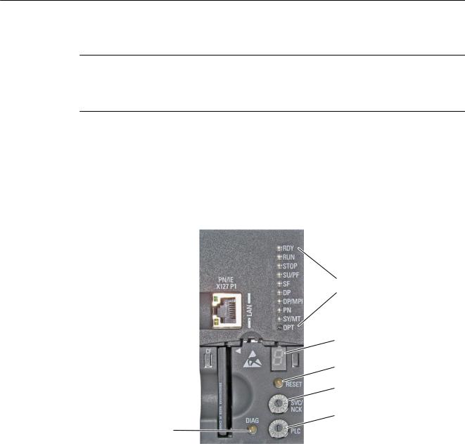
3.4.1Overview of operating and display elements
/(' GLVSO \V
VHJPHQW GLVSO \
5HVHW XWWRQ 1&. VW UW XS VZLWFK
3/& PRGH VHOHFWRU VZLWFK
'L JQRVWLFV XWWRQ ',$*QR IXQFWLRQ
Figure 3-4 Position of operator control and display elements
3.4.2LED displays
Table 3-1 |
Meaning of LED states |
|
|
|
|
|
|
Name |
Function |
Status |
Meaning |
RDY |
Ready |
Red |
Thereisatleastonefault(e.g.RESET,watchdogmonitoring |
|
|
|
etc.) or the NCU is booting up. |
|
|
Flashing red/orange |
Error accessing CompactFlash Card |
|
|
(0.5 Hz) |
|
|
|
Orange |
Accessing CompactFlash Card |
26 |
NCU 7x0.3 PN, NCU 7x0.3B PN |
Manual, 06/2014, 6FC5397-1EP40-5BA1 |
|
|
|
Description |
|
|
|
|
|
|
|
3.4 Operator control and display elements |
|
|
|
|
Name |
Function |
Status |
Meaning |
|
|
Flashing orange (0.5 Hz) |
Updating the firmware of the connected DRIVE-CLiQ |
|
|
|
components |
|
|
Flashing orange (2 Hz) |
Firmware update is complete for components. Wait for |
|
|
|
POWER ON for the components in question. |
|
|
Green |
NC powered up and everything in cyclic mode |
|
|
Flashing green/orange or red/ |
LED-supported recognition of connected DRIVE-CLiQ |
|
|
orange (1 Hz) |
component is activated: (p0124[0] = 1). |
RUN |
PLC RUN |
Green |
PLC ready to operate |
STOP |
PLC STOP |
Orange |
PLC stopped |
SU/PF |
PLC FORCE |
Red |
FORCE activated |
SF |
PLC SF |
Red |
PLC group error |
DP |
BUS1 F |
Red |
PROFIBUS group error X126 |
DP/MPI |
BUS2 F |
Red |
PROFIBUS group error X136 |
PN |
PN Fault |
Red |
PROFINET IO group error X150 |
SY/MT |
MAINT |
Orange |
● Synchronization status (SY): No function |
|
|
|
● Maintenance status (MT) of the NCU: |
|
|
|
Maintenance request pending |
OPT |
- |
- |
No function |
Important LED states
●If all the LEDs are flashing, the PLC must be reset via the mode selector (move switch to position "3" to reboot).
●WhiletheNCUispoweringup,allLEDsbrieflylightuporange.Youcancarryoutadetailed diagnosis using a PG/PC and the operating software.
Additional references
●You can find a detailed description of LED states during power-up in the "NCU Operating System(IM7)"sectionoftheBasesoftwareandOperatingSoftwareCommissioningManual.
●For information on drive faults and alarms, see also: SINAMICS S120/S150 List Manual (LH1)
3.4.37-segment display
Displaying messages
The 7-segment display is located behind the blanking plate of the NCU. It serves as a status display during startup and performs the following tasks:
●Output of test and diagnostic messages.
●Output of status messages during booting
NCU 7x0.3 PN, NCU 7x0.3B PN |
27 |
Manual, 06/2014, 6FC5397-1EP40-5BA1 |

Description
3.4 Operator control and display elements
Critical messages
●During normal operation, "6" appears here and the dot flashes.
●An "8" indicates that the fan is defective or that the NCU is operating without a fan.
Additional references
Basic Software and Operating Software Commissioning Manual (IM7), Chapter "System startup displays".
3.4.4RESET button
Arrangement
The RESET button is located behind the blanking cover.
Performing a reset operation
The reset operation resets the NCU and forces a new power-up. It is similar to a "Power On Reset" except that the 24 V power supply does not have to be switched off.
28 |
NCU 7x0.3 PN, NCU 7x0.3B PN |
Manual, 06/2014, 6FC5397-1EP40-5BA1 |
Description
3.5 Dual fan/battery module
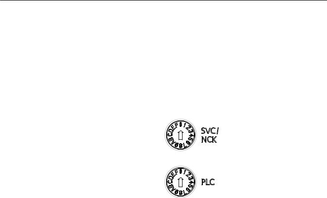
3.4.5Start-up and mode selector switch
Layout
The NCU has two coding rotary switches in the lower section of the front panel:
●The upper switch (labeled SVC/NCK) is the NCK commissioning switch. Setting during normal operation: "0"
●The lower switch (labeled PLC) is the PLC mode selector switch. Setting during normal operation: "0"
1&. FRPPLVVLRQLQ VZLWF
3/& PRGH VHOHFWRU VZLWF
Figure 3-5 Startup and mode selector switch
Additional references
CNC Commissioning Manual Part 1 (NCK, PLC, drive)
3.5Dual fan/battery module
Functions of the dual fan/battery module
The dual fan/battery module has the following tasks:
●Cooling the CPU by means of two redundant fans.
●Buffering of the real time clock.
The temperature inside the NCU and the correct functioning of the fan are monitored. Fan faults are displayed and can be read out by means of the diagnostic buffer.
●Fan alarm alarm 2110 "NCK temperature alarm": if one of the two fans no longer rotates or the speed is out of tolerance.
●Fan fault alarm 2120 "NCK fan alarm type %1": if none of the fans rotate.
If the software does not respond within approx. 1 minute, the components are shut down automatically and the status is indicated by means of the red SF LED.
You can find more information on the alarms in the Diagnostics Manual.
NCU 7x0.3 PN, NCU 7x0.3B PN |
29 |
Manual, 06/2014, 6FC5397-1EP40-5BA1 |

Description
3.5 Dual fan/battery module
Additional information on the diagnostics buffer is provided in the Function Manual Basic Functions, see PLC signal DB10 DBX109.6 (fan temperature alarm).
Fans
The temperature is sensed at several locations within the NCU. The fan is automatically switched in when the temperature thresholds set in the factory are exceeded. A hysteresis function prevents frequent fan start/stop operations.
If natural convection is not sufficient to ensure cooling of the NCU, the fans integrated in the dual fan/battery module are switched on when required (except for an NCU 730.3B PN with PLC 319-3 DP/PN, in this case, the fan runs continuously):
●After switching the NCU on, the fan is activated for a brief period of time (function test) before turning itself off again.
●The temperature is sensed at several locations within the NCU. The fan is automatically switched in when the temperature thresholds set in the factory are exceeded. A hysteresis function prevents frequent fan start/stop operations.
Note
The NCU cannot be operated without fans, i.e. it will not power up if the dual fan/battery module is not functioning. The RDY LED flashes red/orange with 0.5 Hz, all other LEDs light up orange. The state can only be exited by switching the NCU off.
Battery
A 3 V lithium battery is installed in the dual fan/battery module; this can be replaced when required. The battery is pre-assembled with an approximately 4 cm long cable with plug connector.Theappropriatematingconnectorisattachedtoasmallcircuitboardforconnection in the dual fan/battery module.
Note
Please dispose of used batteries in the specially provided collection points on site. This will ensure that the batteries are recycled in the correct manner or treated as special waste.
Note
The backup time of a used type of battery is at least 3 years. Exceeding this backup time risks loss of data.
30 |
NCU 7x0.3 PN, NCU 7x0.3B PN |
Manual, 06/2014, 6FC5397-1EP40-5BA1 |
 Loading...