


840D sl
Table of contents
 Loading...
SINUMERIK 840D sl
Detailed Maschine Data Description
Parameter Manual
Machine and
Setting Data 1
Index I
Valid for
Control
SINUMERIK 840D sl/ 840DE sl
Software Version
NCU Systemsoftware für 840D sl/ 840DE sl 2.6 SP1
03/2010
-
Legal information
Warning notice systemt
This manual contains notices you have to observe in order to ensure your personal safety, as well as to
prevent damage to property. The notices referring to your personal safety are highlighted in the manual
by a safety alert symbol, notices referring only to property damage have no safety alert symbol. These
notices shown below are graded according to the degree of danger.
DANGER
indicates that death or severe personal injury will result if proper precautions are not taken.
WARNING
indicates that death or severe personal injury may result if proper precautions are not taken.
CAUTION
with a safety alert symbol, indicates that minor personal injury can result if proper precautions are not
taken.
CAUTION
without a safety alert symbol, indicates that property damage can result if proper precautions are not taken
NOTICE
indicates that an unintended result or situation can occur if the corresponding information is not taken into
account.
If more than one degree of danger is present, the warning notice representing the highest degree of danger will be used. A notice warning of injury to persons with a safety alert symbol may also include a warning
relating to property damage.
Qualified Personnel
The product/system described in this documentation may be operated only by personnel qualified for the
specific task in accordance with the relevant documentation for the specific task, in particular its warning
notices and safety instructions. Qualified personnel are those who, based on their training and experience,
are capable of identifying risks and avoiding potential hazards when working with these products/systems:
Proper use of Siemens products
Note the following:
WARNING
Siemens products may only be used for the applications described in the catalog and in the relevant technical documentation. If products and components from other manufacturers are used, these must be
recommended or approved by Siemens. Proper transport, storage, installation, assembly, commissioning,
operation and maintenance are required to ensure that the products operate safely and without any problems. The permissible ambient conditions must be adhered to. The information in the relevant documentation must be observed.
Trademarks
All names identified by ® are registered trademarks of the Siemens AG. The remaining trademarks in this
publication may be trademarks whose use by third parties for their own purposes could violate the rights
of the owner.
Copyright Siemens AG 2010 All Rights Reserved
The reproduction, transmission, or use of this document or its contents is not permitted without express written permission. Failure to
observe this rule will lead to damage claims. All rights reserved, especially those relating to granting patents or GM registration.
Siemens AG
Industry Sector
Postfach 4848
90327 NÜRNBERG
GERMANY
Siemens Aktiengesellschaft SINUMERIK 840D sl Detailed Maschine Data Description (AMDsl)
Disclaimer of Liability
We have reviewed the contents of this publication to ensure consistency with the hardware and software described. Since variance cannot be precluded entirely, we cannot guarantee full consistency.
However, the information in this publication is reviewed regularly and
any necessary corrections are included in subsequent editions.
© Siemens AG 2010
Technical data subject to change.
03/2010

Preface
Structure of the documentation
The SINUMERIK documentation is available in three versions:
General Documentation
User Documentation
Manufacturer/Service Documentation
Information on the following topics is available at
http://www.siemens.com/motioncontrol/docu:
Ordering documentation
Here you can find an up-to-date overview of publications.
Downloading documentation
Links to more information for downloading files from Service & Support.
Researching documentation online
Information on DOConCD and direct access to the publications in
DOConWEB.
Compiling individual documentation on the basis of Siemens contents with the
My Documentation Manager (MDM), refer to http://www.siemens.com/mdm.
My Documentation Manager provides you with a range of features for generating your own machine documentation.
Target group
Benefits
Training and FAQs
Information on the range of training courses and FAQs (frequently asked
questions) are available via the page navigation.
This documentation is intended for project engineers, commissioning engineers,
machine operators, service and maintenance personnel.
The Parameter Manual enables the intended target group to evaluate error and
fault indications and to respond accordingly.
With the help of the Parameter Manual, the target group has an overview of the
various diagnostic options and diagnostic tools.
SINUMERIK 840D sl, Detailed Maschine Data Description (AMDsl), 03/2010
iii Siemens AG 2010 All Rights Reserved
Preface 03/2010
Standard version
This Parameter Manual only describes the functionality of the standard version.
Extensions or changes made by the machine tool manufacturer are documented
by the machine tool manufacturer.
Other functions not described in this documentation might be executable in the
control. This does not, however, represent an obligation to supply such functions
with a new control or when servicing.
Further, for the sake of simplicity, this documentation does not contain all detailed
information about all types of the product and cannot cover every conceivable
case of installation, operation or maintenance.
Technical Support
If you have any questions, please contact the following hotline:
Europe / Africa
Phone
Fax
€0.14/min. from German landlines, max. 0.42 €/min for calls from a mobile phone.
Internet
Phone
Fax
Email
Phone
Fax
Email
+49 180 5050 222
+49 180 5050 223
http://www.siemens.de/automation/support-request
America
+1 423 262 2522
+1 423 262 2200
mailto:techsupport.sea@siemens.com
Asia / Pacific
+86 1064 757575
+86 1064 747474
mailto:support.asia.automation@siemens.com
Note
National phone numbers for technical support are provided under the following
Internet address: http://www.automation.siemens.com/partner
iv
SINUMERIK 840D sl, Detailed Maschine Data Description (AMDsl), 03/2010
Siemens AG 2010 All Rights Reserved

03/2010 Preface
Questions about this documentation
If you have any queries (suggestions, corrections) in relation to this documentation, please send a fax or email to the following address
Fax
Email
A fax form is available at the end of this document.
SINUMERIK Internet address
http://www.siemens.com/sinumerik
+49 9131 98 2176
mailto:docu.motioncontrol@siemens.com
Siemens AG 2010 All Rights Reserved
SINUMERIK 840D sl, Detailed Maschine Data Description (AMDsl), 03/2010
v

Preface 03/2010
vi
SINUMERIK 840D sl, Detailed Maschine Data Description (AMDsl), 03/2010
Siemens AG 2010 All Rights Reserved

Table of Contents
1 Machine and setting data. . . . . . . . . . . . . . . . . . . . . . . . . . . . . . . . . . . . . . . . . . . . . . . 1-9
1.1 Important information about the data tables . . . . . . . . . . . . . . . . . . . . . . . . . . 1-9
1.1.1 Structure of the data tables . . . . . . . . . . . . . . . . . . . . . . . . . . . . . . . . . . . . . 1-9
1.1.2 Meaning of table fields . . . . . . . . . . . . . . . . . . . . . . . . . . . . . . . . . . . . . . . . 1-10
1.1.3 Overview of the data . . . . . . . . . . . . . . . . . . . . . . . . . . . . . . . . . . . . . . . . . . 1-17
1.2 Display machine data . . . . . . . . . . . . . . . . . . . . . . . . . . . . . . . . . . . . . . . . . . 1-21
1.3 General machine data . . . . . . . . . . . . . . . . . . . . . . . . . . . . . . . . . . . . . . . . . . 1-24
1.3.1 System settings . . . . . . . . . . . . . . . . . . . . . . . . . . . . . . . . . . . . . . . . . . . . . . 1-24
1.3.2 Override switch settings . . . . . . . . . . . . . . . . . . . . . . . . . . . . . . . . . . . . . . . 1-169
1.3.3 System specific memory settings . . . . . . . . . . . . . . . . . . . . . . . . . . . . . . . . 1-227
1.4 Channel-specific machine data . . . . . . . . . . . . . . . . . . . . . . . . . . . . . . . . . . 1-294
1.4.1 Basic channel machine data . . . . . . . . . . . . . . . . . . . . . . . . . . . . . . . . . . . . 1-294
1.4.2 Machine data for grinding function . . . . . . . . . . . . . . . . . . . . . . . . . . . . . . . 1-394
1.4.3 Channel auxiliary function settings . . . . . . . . . . . . . . . . . . . . . . . . . . . . . . . 1-396
1.4.4 Transformation definitions in channel . . . . . . . . . . . . . . . . . . . . . . . . . . . . . 1-425
1.4.5 Punching and nibbling . . . . . . . . . . . . . . . . . . . . . . . . . . . . . . . . . . . . . . . . . 1-480
1.4.6 Channel-specific memory settings . . . . . . . . . . . . . . . . . . . . . . . . . . . . . . . 1-494
1.5 Axis-specific machine data . . . . . . . . . . . . . . . . . . . . . . . . . . . . . . . . . . . . . 1-514
1.5.1 Configuration . . . . . . . . . . . . . . . . . . . . . . . . . . . . . . . . . . . . . . . . . . . . . . . . 1-514
1.5.2 Encoder matching . . . . . . . . . . . . . . . . . . . . . . . . . . . . . . . . . . . . . . . . . . . . 1-532
1.5.3 Closed-loop control . . . . . . . . . . . . . . . . . . . . . . . . . . . . . . . . . . . . . . . . . . . 1-539
1.5.4 Reference point approach . . . . . . . . . . . . . . . . . . . . . . . . . . . . . . . . . . . . . . 1-583
1.5.5 Spindles. . . . . . . . . . . . . . . . . . . . . . . . . . . . . . . . . . . . . . . . . . . . . . . . . . . . 1-600
1.5.6 Monitoring functions . . . . . . . . . . . . . . . . . . . . . . . . . . . . . . . . . . . . . . . . . . 1-624
1.5.7 Safety Integrated . . . . . . . . . . . . . . . . . . . . . . . . . . . . . . . . . . . . . . . . . . . . . 1-641
1.5.8 Travel to fixed stop . . . . . . . . . . . . . . . . . . . . . . . . . . . . . . . . . . . . . . . . . . . 1-674
1.5.9 Axis-specific memory settings . . . . . . . . . . . . . . . . . . . . . . . . . . . . . . . . . . . 1-704
1.6 Setting data . . . . . . . . . . . . . . . . . . . . . . . . . . . . . . . . . . . . . . . . . . . . . . . . . 1-706
1.6.1 General setting data . . . . . . . . . . . . . . . . . . . . . . . . . . . . . . . . . . . . . . . . . . 1-706
1.6.2 Channel-specific setting data . . . . . . . . . . . . . . . . . . . . . . . . . . . . . . . . . . . 1-722
1.6.3 Axis-specific setting data. . . . . . . . . . . . . . . . . . . . . . . . . . . . . . . . . . . . . . . 1-752
1.7 Machine data cycles . . . . . . . . . . . . . . . . . . . . . . . . . . . . . . . . . . . . . . . . . . 1-770
1.7.1 General configuration machine data . . . . . . . . . . . . . . . . . . . . . . . . . . . . . . 1-770
1.7.2 General cycle machine data . . . . . . . . . . . . . . . . . . . . . . . . . . . . . . . . . . . . 1-782
1.7.3 Channel-specific configurations machine data . . . . . . . . . . . . . . . . . . . . . . 1-788
1.7.4 Channel-specific cycle machine data . . . . . . . . . . . . . . . . . . . . . . . . . . . . . 1-795
1.7.5 Axis-specific configuration machine data . . . . . . . . . . . . . . . . . . . . . . . . . . 1-797
1.7.6 General configuration setting data . . . . . . . . . . . . . . . . . . . . . . . . . . . . . . . 1-798
1.7.7 General cycle setting data. . . . . . . . . . . . . . . . . . . . . . . . . . . . . . . . . . . . . . 1-798
1.7.8 Cannel-specific configuration setting data. . . . . . . . . . . . . . . . . . . . . . . . . . 1-817
1.7.9 Channel-specific cycle setting data . . . . . . . . . . . . . . . . . . . . . . . . . . . . . . . 1-820
SINUMERIK 840D sl, Detailed Maschine Data Description (AMDsl), 03/2010
vii Siemens AG 2010 All Rights Reserved

Table of Contents 03/2010
1.8 Machine data compile cycles . . . . . . . . . . . . . . . . . . . . . . . . . . . . . . . . . . . 1-837
1.8.1 General machine data compile cycles. . . . . . . . . . . . . . . . . . . . . . . . . . . . . 1-837
1.8.2 Channel-specific machine data compile cycles. . . . . . . . . . . . . . . . . . . . . . 1-839
1.8.3 Axis-specific machine data compile cycles . . . . . . . . . . . . . . . . . . . . . . . . . 1-859
IIndex . . . . . . . . . . . . . . . . . . . . . . . . . . . . . . . . . . . . . . . . . . . . . . . . . . . . . . . . . . . . . . I-863
viii
SINUMERIK 840D sl, Detailed Maschine Data Description (AMDsl), 03/2010
Siemens AG 2010 All Rights Reserved

Machine and setting data 1
1.1 Important information about the data tables
This list manual provides information on all the machine and setting data in a concise table format. A functional description of the data is provided in the function
manual indicated in the cross reference.
You can also find more information in:
HMI Online Help directly on the control
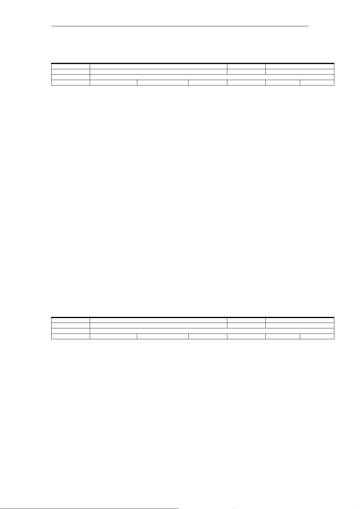
1.1.1 Structure of the data tables
Standard table
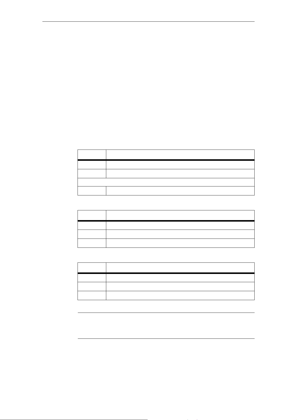
The standard table contains all the important information about the data:
MD number Identifier Display filter Reference
Unit Name Data type Activation
Attributes
System Dimension Default value Minimum value Maximum value Protection Class
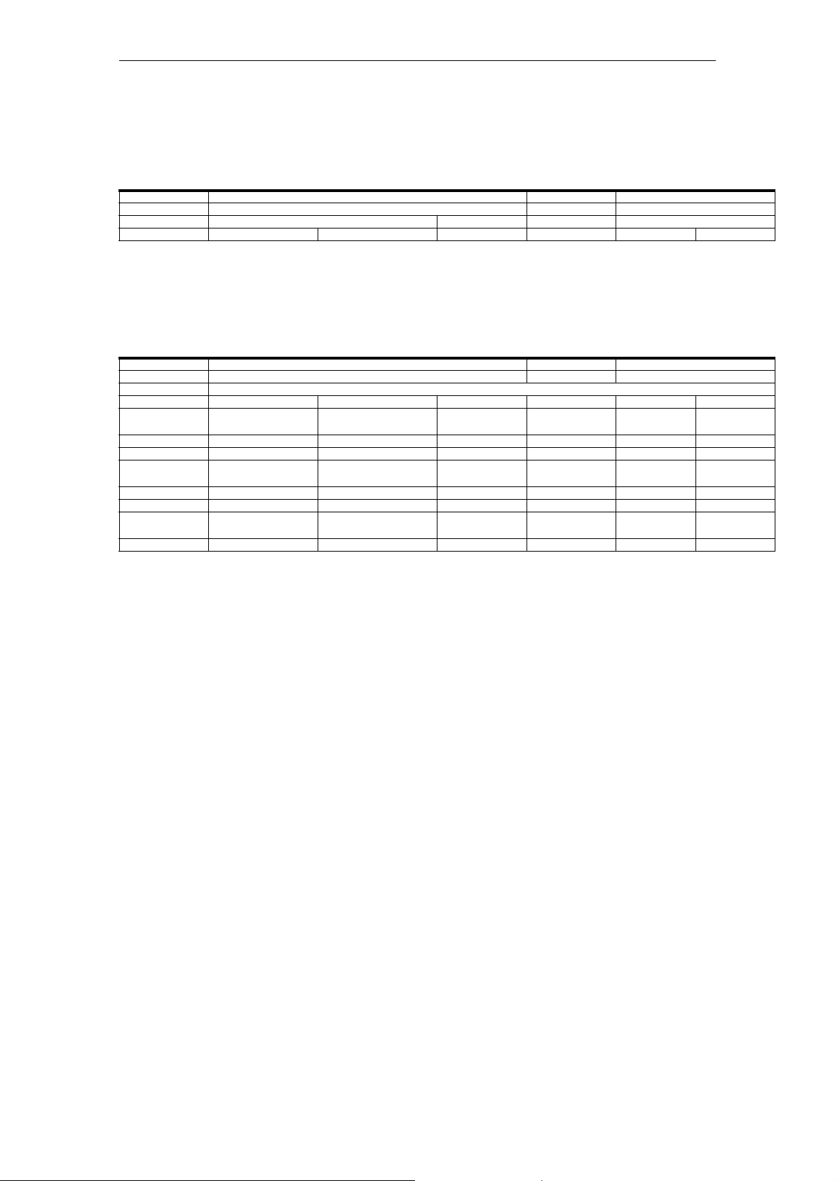
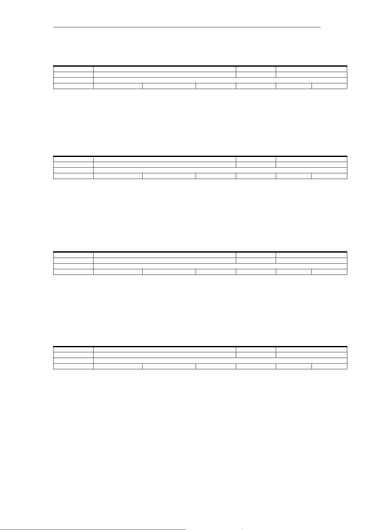
Expanded table
The expanded table includes data from the standard table plus additional rows
with system-specific values.
MD number Identifier Display filter Reference
Unit Name Data type Activation
Attributes
- Dimension Default value Minimum value Maximum value Protection Class
<System 1> - Default value - - -/-
<System 2> - - - - -1/-
A minus sign "-" in a field means that the same value as for System 1 applies for
the specified system.
The entry "-1/-" in the "Protection" field means that the machine data is not available for the specified system.
Siemens AG 2010 All Rights Reserved
SINUMERIK 840D sl, Detailed Maschine Data Description (AMDsl), 03/2010
1-9

1 Machine and setting data 03/2010
1.1 Important information about the data tables
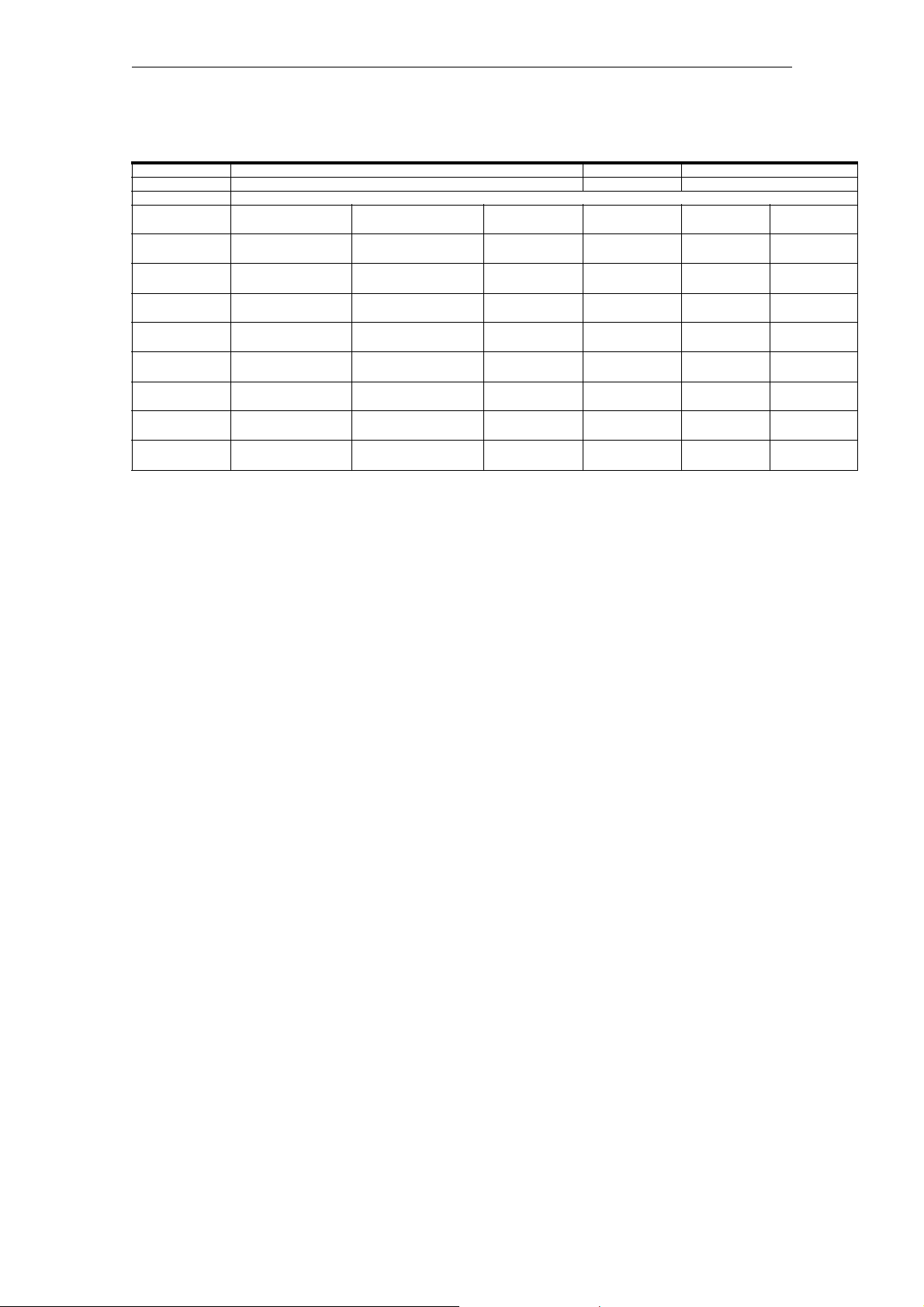
Example:
10050 SYSCLOCK.CYCLE_TIME N01, N05, N11 G3
s Basic system clock cycle DOUBLE POWER ON
SFCO
- - 0.004 0.000125 0.031 7/2 M
710-2a2c - 0.002 0.001 0.008 -/-
1.1.2 Meaning of table fields
MD number
The "MD number" field contains the machine data number. This number is displayed in the data lists on the user interface of the control.
Identifier
Reference
The "Identifier" field contains the unique alphanumeric identifier of the machine
data. The machine data is, for example, addressed by means of this identifier
(with an additional label) for programming in the part program.
This identifier is displayed in the data lists on the user interface of the control.
As a cross reference to the functional description of the data, the "Reference" field
contains the short designation of a supporting manual for a specific function manual.
Reference is made to the following documents:
Function Manual of basic machines, supporting manuals: A2, A3, B1, B2,
D1, F1, G2, H2, K1, K2, N2, P1, P3, R1, S1, V1, W1, Z1
Function Manual of expanded functions, supporting manuals: A4, B3, B4,
F3, H1, K3, K5, M1. M5, N3, N4, P2, P5, R2, S3, S7, T1, W3, W4, Z2
Function Manual of special functions, supporting manuals: F2, G1, G3, K6,
M3, S9, T3, TE01, TE02, TE1, TE3, TE4, TE6, TE7, TE8, TE9, V2, W5,
W6, Z3
Funktionshandbuch Antriebsfunktionen, Unterbücher, FBA: DB1, DD1,
DD2, DE1, DF1, DG1, DL1, DM1, DS1, DÜ1
1-10
Funktionshandbuch Antriebsfunktionen, Unterbücher, FBA: DB1, DD1,
DD2, DE1, DF1, DG1, DL1, DM1, DS1, DÜ1
Function Manual Safety Integrated, FBSI
Function Manual Turn, FBMA
Function Manuall of Tool Management, FBW
Function Manual of ISO-dialects for SINUMERIK, FBFA
Siemens AG 2010 All Rights Reserved
SINUMERIK 840D sl, Detailed Maschine Data Description (AMDsl), 03/2010

03/2010 1 Machine and setting data
1.1 Important information about the data tables
Function Manual of Synchronized actions, FBSY
Programmiing Manual Fundamentals, PG
Programmiing Manual Job planing, PGA
Unit
The "Unit" field contains the physical unit of the data in the default setting. A minus
sign "-" means that the data does not have a physical unit.
Note
For machine data of the Performance 2 [P2] control module, the unit or units are
shown with a filter in row 2, column 1.
Name
The "Name" field contains the name of the data in plain text.
Activation
The "Activation" field contains the action that must be performed by the user in
order for a change to take effect.
Activation User action
po POWER ON Otherwise:
HMI softkey "Reset (po)" (SINUMERIK Operate/HMI-
Advanced SW 7.5 or higher)
HMI softkey "NCK-Reset" (HMI-Embedded)
Reset button on the front of the NCU module
Switch voltage off/on
cf NEW_CONF HMI softkey: "Activate MD"
re RESET Otherwise:
Channel reset: DBn.DBX 7.7 where n = 21, 22, 23, etc.
Mode group reset: DB11.DBX n.7 where n = 0, 20, 40, etc.
NCK reset: DB11.DBX n.7 where n = 0, 20, 40, etc. in all mode
groups of the control
Program end reset (M02/M30)
so IMMEDI-
ATELY
-
The activation levels are listed according to their priority.
po = highest priority
so = lowest priority
Siemens AG 2010 All Rights Reserved
SINUMERIK 840D sl, Detailed Maschine Data Description (AMDsl), 03/2010
1-11

1 Machine and setting data 03/2010
1.1 Important information about the data tables
Axis-specific machine data with effectiveness criterion Reset.
To activate axis-specific machine data with effectiveness criterion RESET, trigger a channel reset in the channel in which the axis is currently located.
Note
Mode group reset generates a reset in all channels which have been combined
into one machining unit.
Notice
PLC-controlled axes always require an axial reset.
See Function Manual Extended Functions, Chapter "P2: Positioning Axes" >
"Influence of PLC" > "PLC-controlled Axes".
Protection
Protection
The "Protection" field contains the protection level for reading or writing to the
data in the format: Read / write.
Value Protection level
0 or 10 System
1 or 11 Manufacturer
2 or 12 Service
3 or 13 User
4 or 14 Key-operated switch setting 3
5 or 15 Key-operated switch setting 2
6 or 16 Key-operated switch setting 1
7 or 17 Key-operated switch setting 0
The protection level for user data (GUD) is defined with the numbers 10 to 17.
1-12
SINUMERIK 840D sl, Detailed Maschine Data Description (AMDsl), 03/2010
Siemens AG 2010 All Rights Reserved

03/2010 1 Machine and setting data
1.1 Important information about the data tables
Class
The data class attribute of machines, setting and option data is usually derived
from the write authorization of the relevant data.
The following data classes are used:
Data class Write authorization Access authorization
S System Protection level 0 (password: System )
M Manufacturer/ Service Protection level 1 and 2 (password: Service)
U User Protection level 3 (password: User)
Protection level 4 to 7 (keyswitch)
Display filter
The "Display filter" field contains the identifier of the data filter setting that enables
the data to be seen. With the filter setting, the exact data areas needed at a given
time can be selected for display.
ID Data area
EXP Expert mode
Drive machine data
D00 Display signals
D01 Controller data
D02 Monitoring/limiting functions
D03 Message data
D04 Status data
D05 Motor/power unit
D06 Measuring system
D07 Safety Integrated
D08 Standard machine
General machine data
N01 Configuration/scaling
N02 Memory configuration
N03 PLC machine data
N04 Drive control
N05 Status data/diagnostics
N06 Monitoring/limiting functions
N07 Auxiliary functions
N08 Corrections/compensations
N09 Technological functions
Siemens AG 2010 All Rights Reserved
SINUMERIK 840D sl, Detailed Maschine Data Description (AMDsl), 03/2010
1-13

1 Machine and setting data 03/2010
1.1 Important information about the data tables
ID Data area
N10 I/O configuration
N11 Standard machine
A12 External language
A13 Safety Integrated
A14 Selection for Safety Integrated
Channelspecific machine data
C01 Configuration
C02 Memory configuration
C03 Initial settings
C04 Auxiliary functions
C05 Speeds
C06 Monitoring/limiting functions
C07 Transformations
C08 Corrections/compensations
C09 Technological functions
C10 Standard machine
C11 External languages
Axis-specific machine data
A01 Configuration (including memory)
A02 Measuring system
A03 Machine geometry
A04 Speeds/accelerations
A05 Monitoring/limiting functions
A06 Spindle
A07 Controller data
A08 Status data
A09 Corrections/compensations
A10 Technological functions
A11 Standard machine
A12 External language
A13 Safety Integrated
A14 Selection for Safety Integrated
Display machine data
H01 ShopMill
1-14
H02 ShopTurn
H03 ManualTurn
Siemens AG 2010 All Rights Reserved
SINUMERIK 840D sl, Detailed Maschine Data Description (AMDsl), 03/2010

03/2010 1 Machine and setting data
1.1 Important information about the data tables
ID Data area
H04 Access levels
H05 Standard machine
System
The "System" field contains the system for which the data is valid.
ID System
840Dsl 840D systems solution line
710 NCU 710
720 NCU 720
730 NCU 730
If this field is empty, the data is valid for all systems.
Dimension
Value range
Additional identifiers:
iajc i = number of axes
j = number of channels
For example: 6a2c = 6 axes, 2 channels
The "Dimension" field contains the number of elements of a data field.
The "Minimum value" and "Maximum value" fields contain the lower limit and
upper limit, respectively, of the permissible range of the data.
If the "Minimum value" and "Maximum value" fields contain the string " *** ", an
explicit range is not defined for this data. In this case, the range is determined by
the specified data type.
Siemens AG 2010 All Rights Reserved
SINUMERIK 840D sl, Detailed Maschine Data Description (AMDsl), 03/2010
1-15

1 Machine and setting data 03/2010
1.1 Important information about the data tables
SINUMERIK data types
The "Data type" field contains the following data types:
Data type Value range
BOOLEAN Machine data bit (1 or 0)
BYTE Integer values ( -128 to 127 )
-308
DOUBLE Real values ( ± ( 2.2 * 10
to 1.8 * 10
DWORD Integer values ( -2147483648 to +2147483647 )
DWORD Hex values ( 0 to FFFF FFFF )
STRING Character string (max. 16 characters) consisting of upper-case
letters with digits and underscore
UNSIGNED WORD Integer values ( 0 to 65536 )
SIGNED WORD Integer values ( -32768 to 32767 )
UNSIGNED DWORD Integer values ( 0 to 4294967300 )
SIGNED DWORD Integer values ( -2147483650 to 2147483649 )
WORD Hex values ( 0000 to FFFF )
-37
FLOAT DWORD Real values ( ± ( 8.43 x 10
to "3.37 x 10
UBYTE Integer values ( 0 to 255 )
LONG Integer values ( 4294967296 to 4294967295 )
+308
38
) )
)
SIMATIC data types
The "Data type" field contains the following data types:
Data type Meaning Value range
I8 Integer8 8-bit integer
I16 Integer16 16-bit integer
I32 Integer32 32-bit integer
U8 Unsigned8 8 bits without sign
U16 Unsigned16 16 bits without sign
U32 Unsigned32 32 bits without sign
Float FloatingPoint32 32-bit floating point number
1-16
SINUMERIK 840D sl, Detailed Maschine Data Description (AMDsl), 03/2010
Siemens AG 2010 All Rights Reserved

03/2010 1 Machine and setting data
1.1 Important information about the data tables
Attributes
The "Attributes" field contains additional attributes of the data:
Attribute Meaning
NBUP No Back UP: The data is not backed up as part of the data
backup.
ODLD Only DownLoaD: The data can only be written to via an INI file,
archive, or from the part program.
NDLD No DownLoaD: The data can only be written to via the HMI
user interface.
SFCO SaFety COnfiguration: Component of the "Safety Integrated"
function
SCAL SCaling ALarm: Scaling data; when changed, alarm 4070 is
displayed
LINK LINK description: The data describes a link cluster, component
of the "NCU Link" function
CTEQ ConTainer EQual: The data must be the same for all axes in an
axis container, component of the "Axis container" function
CTDE ConTainer DEscription: The data describes an axis container,
component of the "Axis container" function
1.1.3 Overview of the data
Machine and setting data
The machine and setting data are divided into the following areas:
Range Designation
From 9000 to 9999 Display machine data
From 10000 to 18999 General NC machine data
From 19000 to 19999 Reserved
From 20000 to 28999 Channelspecific machine data
From 29000 to 29999 Reserved
From 30000 to 38999 Axis-specific machine data
From 39000 to 39999 Reserved
From 41000 to 41999 General setting data
From 42000 to 42999 Channel-specific setting data
From 43000 to 43999 Axis-specific setting data
From 51000 to 51299 General configuration machine data
From 51300 to 51999 General cycle machine data
From 52000 to 52299 Channel-specific configuration machine data
Siemens AG 2010 All Rights Reserved
SINUMERIK 840D sl, Detailed Maschine Data Description (AMDsl), 03/2010
1-17

1 Machine and setting data 03/2010
1.1 Important information about the data tables
Range Designation
From 52300 to 52999 Channel-specific cycle machine data
From 53000 to 53299 Axis-specific configuration machine data
From 53300 to 53999 Axis-specific cycle machine data
From 54000 to 54299 General configuration setting data
From 54300 to 54999 General cycle setting data
From 55000 to 55299 Channel-specific configuration setting data
From 55300 to 55999 Channel-specific cycle setting data
From 56000 to 56299 Axis-specific configuration setting data
From 56300 to 56999 Axis-specific cycle setting data
From 61000 to 61999 General machine data for compile cycles
From 62000 to 62999 Channel-specific machine data for compile cycles
From 63000 to 63999 Axis-specific machine data for compile cycles
Data Identifiers
The identifier (designator) specified in the data description is displayed on the
HMI user interface. However, if the data is addressed in the parts program, for
example, the identifier of the relevant data area must precede the data identifier
(designator).
Identifier Data area
$MM_ Display machine data
$MN_/ $SN_
$MNS_/ $SNS_
$MC_/ $SC_
$MCS_/ $SCS_
$MA_/ $SA_
$MAS_/ $SAS_
Characters Meanings
$ System variables
M Machine data (first letter)
S Setting data (first letter)
M, N, C, A, D Subarea (second letter)
S Siemens data (third letter)
General machine/setting data
Channel-specific machine/setting data
Axis-specific machine/setting data
1-18
SINUMERIK 840D sl, Detailed Maschine Data Description (AMDsl), 03/2010
Siemens AG 2010 All Rights Reserved

03/2010 1 Machine and setting data
1.1 Important information about the data tables
Note:
Axis-specific data can also be addressed with the axis name as an index. The
internal axis identifier (AX1, AX2, AX3, etc.) or the identifier specified in
MD10000 $MA_AX_CONF_NAME_TAB can be used as the axis name.
Example: $MA_JOG_VELO[Y1]=2000
The JOG velocity of axis Y1 is 2000 mm/min.
If the content of a machine data is a STRING (e.g., X1) or a hexadecimal value
(e.g., H41), the content must be enclosed in single quotation marks (e.g., 'X1' or
'H41').
Example: $MN_DRIVE_INVERTER_CODE[0]='H14'
A FD module with performance data 9/18 A is present on the first slot of the drive
bus.
Example: $MA_FIX_POINT_POS[0,X1]=500.000
The value 500 is assigned to the first fixed point position on axis 1.
Examples:
$MN_AUXFU_GROUP_SPEC[2]='H41'
Output time of the auxiliary functions of the third auxiliary function group.
$MN_AXCONF_MACHAX_NAME_TAB[0]='X1'
The string "X1" is assigned to name the first machine axis.
$MA_REFP_SET_POS[0,X1]=100.00000
A value of 100 mm is assigned to the first reference point value of axis X1.
Examples:
Assignment to channel-specific machine data:
CHANDATA(1) ;Selection of the
first
;channel
$MC_CHAN_NAME='CHAN1' ;Name of the first
;channel
$MC_AXCONF_GEOAX_NAME_TAB[1]='Y' ;Name of the second
;geometry axis of the
;first channel is Y
R10 = 33.75
...
CHANDATA(2) ;Selection of the sec-
$MC_CHAN_NAME='CHAN2'
...
R10 = 96.88
...
;R10 of the first
channel
ond ;channel
;Name of the second
;channel
;R10 of the second
;channel
Siemens AG 2010 All Rights Reserved
SINUMERIK 840D sl, Detailed Maschine Data Description (AMDsl), 03/2010
1-19

1 Machine and setting data 03/2010
1.1 Important information about the data tables
1-20
SINUMERIK 840D sl, Detailed Maschine Data Description (AMDsl), 03/2010
Siemens AG 2010 All Rights Reserved

03/2010 Machine and Setting Data
1.2 Display machine data
Product: Handbuch_Sinumerik, Version: V12.0, Language: eng
Objects:
1.2 Display machine data
Number Identifier Display filters Reference
Unit Name Data type Active
Attributes
System Dimension Default value Minimum value Maximum value Protection Class
Description: Description
9006 DISPLAY_SWITCH_OFF_INTERVAL --
- Time for screen saver DWORD PowerOn
-
- - 60 0 180 7/3 M
Description: This machine data defines the time in minutes after which the
screen automatically
switches to dark if no key has been pressed on the keyboard in the
meantime.
The value 0 disables automatic light/dark switching.
Note:
The screen is only switched light/dark automatically when IS
screen dark = 0.
Related to:
IS screen dark (DB19, ... DBX0.1)
9009 KEYBOARD_STATE --
- Keyboard shift behavior at booting BYTE PowerOn
-
-- 0 0 2 7/3 M
Description: This machine date defines the Shift behavior (SW-CAPSLOCK) of the
keyboard.
Basic configuration of the Shift behavior of the keyboard
0: SW-CAPSLOCK OFF
2: SW-CAPSLOCK ON
9032 HMI_MONITOR --
- Define PLC data for HMI screen info STRING PowerOn
-
- - - - 7/1 M
Description: Pointer, with offset, to a PLC data block. This is required to
report
HMI monitor information to the PLC, e.g active HMI task.
Format: PLC-specific format for specifying a data block with byte
offset,
e.g. DB60.DBB10 for data block 60, byte 10.
The monitor information reported by the HMI has a maximum length
of 8 bytes.
Siemens AG 2010 All Rights Reserved
SINUMERIK 840D sl,, Detailed Maschine Data Description (AMDsl), 03/2010
1-21

Machine and Setting Data 03/2010
1.2 Display machine data
9056 ALARM_ROTATION_CYCLE --
- Rotation cycle time for alarm display DWORD PowerOn
-
- - 0 0 10000 7/3 M
Description: Rotation cycle time in the alarm display:
<500: no rotation in the alarm line
500 - 10000: cycle duration of alarm rotation in milliseconds
If a valid cycle time has been set, all alarms are displayed in the
alarm line one after the other.
Each alarm is displayed for the specified time until it is
replaced by the next alarm.
If no alarm is present, cycle alarms or program messages are dis-
played, if required. However, these do not rotate.
9100 CHANGE_LANGUAGE_MODE --
- Language selection mode BYTE Immediately
-
-- 1 1 2 7/3 I
Description: Language selection mode is defined:
1 = directly via selection list
2 = via setting of the 1st and 2nd language
9102 SHOW_TOOLTIP --
- Display tooltip BYTE Immediately
-
-- 1 0 1 7/3 U
Description: If the MD has been set to 1, tooltips will be displayed.
9103 TOOLTIP_TIME_DELAY -s Time delay tooltip display BYTE Immediately
-
- - 1 0 60 7/3 U
Description: Time delay for display of the tooltips in seconds.
9105 HMI_WIDE_SCREEN --
- Display of the HMI as wide screen with OEM area always
visible
-
-- 0 0 1 7/2 M
Description: Display of the HMI as wide screen. Above the HMI there is a sepa-
BYTE PowerOn
rate application field that is designed by the machine manufacturer.
9106 SERVE_EXTCALL_PROGRAMS --
- Process EXTCALL calls BYTE PowerOn
-
-- 1 0 1 7/3 M
Description: HMI processes reload requirements of the NC for EXTCALL calls.
1-22
SINUMERIK 840D sl,, Detailed Maschine Data Description (AMDsl), 03/2010
Siemens AG 2010 All Rights Reserved

03/2010 Machine and Setting Data
1.2 Display machine data
9107 DRV_DIAG_DO_AND_COMP_NAMES --
- Expanded drive diagnostics: DO and components BYTE Immediately
-
-- 0 0 3 7/3 I
Description: 0: DO and component type names
1: Real DO names and component type names
2: DO type names and real component names
3: Reale DO names and real component names
9108 ENABLE_EPS_SERVICES --
- Activation of ePS Network services BYTE Immediately
-
-- 0 0 1 7/3 M
Description: If the machine data has been set to 1, the "ePS Network services"
softkey appears as the operating area.
9110 ACCESS_HMI_EXIT --
- Protection level of exit softkey BYTE PowerOn
-
-- 1 0 7 7/2 M
Description: Protection level for the exit softkey (HMI restart) in the operat-
ing area menu
9900 MD_TEXT_SWITCH --
- Plaintexts instead of MD identifier BOOLEAN Immediately
-
-- 0 - - 7/3 U
Description: If the MD has been set to 1, clear text is displayed on the opera-
tor panel instead of the machine data identifiers.
9990 SW_OPTIONS --
- Enable HMI software options DWORD Immediately
-
-- 0 - - 1/1 I
Description: Here you can enable the HMI software options
Siemens AG 2010 All Rights Reserved
SINUMERIK 840D sl,, Detailed Maschine Data Description (AMDsl), 03/2010
1-23
Machine and Setting Data 03/2010
1.3 General machine data
1.3 General machine data
Number Identifier Display filters Reference
Unit Name Data type Active
Attributes
System Dimension Default value Minimum value Maximum value Protection Class
Description: Description
1.3.1 System settings
10000 AXCONF_MACHAX_NAME_TAB N01, N11 K2,F1,G2,F2,K5,M1
- Machine axis name STRING PowerOn
710-6a2c 31 X1,Y1,Z1,A1,B1,C1 - - 7/2 M
710-31a10c 31 X1,Y1,Z1,A1,B1,C1,U1...- - 7/2 M
710-31a10c6 31 X1,Y1,Z1,A1,B1,C1 - - 7/2 M
720-6a2c 31 X1,Y1,Z1,A1,B1,C1 - - 7/2 M
720-31a10c 31 X1,Y1,Z1,A1,B1,C1,U1...- - 7/2 M
720-31a10c6 31 X1,Y1,Z1,A1,B1,C1 - - 7/2 M
730-6a2c 31 X1,Y1,Z1,A1,B1,C1 - - 7/2 M
730-31a10c 31 X1,Y1,Z1,A1,B1,C1,U1...- - 7/2 M
730-31a10c6 31 X1,Y1,Z1,A1,B1,C1 - - 7/2 M
Description: List of the machine axis identifiers.
The name of the machine axis is entered in this MD.
In addition to the fixed, defined machine axis identifiers "AX1",
"AX2" ..., user-defined identifiers for the machine axes can also
be assigned in this data.
The identifiers defined here can be used parallel to the fixed,
defined identifiers for addressing axial data (e.g. MD) and
machine axis-related NC functions (reference point approach, axial
measurement, travel to fixed stop).
Special cases:
• The input machine axis name must not conflict with the names
and assignments of the geometry axes (MD20060
$MC_AXCONF_GEOAX_NAME_TAB, MD20050
$MC_AXCONF_GEOAX_ASSIGN_TAB) or channel axes (MD20080
$MC_AXCONF_CHANAX_NAME_TAB, MD20070 $MC_AXCONF_MACHAX_USED).
• The input machine axis name must not be the same as the names
for Euler angles (MD10620 $MN_EULER_ANGLE_NAME_TAB), names for
path-relevant orientation (MMD10624
$MN_ORIPATH_LIFT_VECTOR_TAB), names for normal vectors
(MD10630 $MN_NORMAL_VECTOR_NAME_TAB), names for directional
vectors (MD10640 $MN_DIR_VECTOR_NAME_TAB), names for rotation
vectors (MD10642 $MN_ROT_VECTOR_NAME_TAB), names for intermediate vector components (MD10644 $MN_INTER_VECTOR_NAME_TAB),
names for intermediate circle point coordinates with CIP
(MD10660 $MN_INTERMEDIATE_POINT_NAME_TAB) or the names for
interpolation parameters (MD10650 $MN_IPO_PARAM_NAME_TAB).
1-24
SINUMERIK 840D sl, Detailed Maschine Data Description (AMDsl), 03/2010
Siemens AG 2010 All Rights Reserved

03/2010 Machine and Setting Data
1.3 General machine data
• The input machine axis name must not include any of the following reserved address letters:
D Tool offset (D function) E Reserved
F Feedrate (F function) G Preparatory function
H Auxiliary function (H function) L Subroutine call
M Miscellaneous function (M function) N Subblock
P Subroutine number of passes R Arithmetic parameters
S Spindle speed (S function) T Tool (T function)
The name must not include any keywords (e.g. DEF, SPOS etc.) or
pre-defined identifiers (e.g. ASPLINE, SOFT).
The use of an axis identifier consisting of a valid address letter
(A, B, C, I, J, K, Q, U, V, W, X, Y, Z), followed by an optional
numerical extension (1-99) gives slightly better block cycle times
than a general identifier.
If no identifier is assigned to a machine axis, then the predefined name ("AXn") applies to the nth machine axis.
Related to:
MD20060 $MC_AXCONF_GEOAX_NAME_TAB (geometry axis name in the
channel [GEOAxisno.]
MD20080 $MC_AXCONF_CHANAX_NAME_TAB (channel axis name in the
channel [Channelaxisno.]
Siemens AG 2010 All Rights Reserved
SINUMERIK 840D sl, Detailed Maschine Data Description (AMDsl), 03/2010
1-25

Machine and Setting Data 03/2010
1.3 General machine data
10002 AXCONF_LOGIC_MACHAX_TAB N01 B3,K2
- Logical NCK machine axis image STRING PowerOn
-
- 31 AX1,AX2,AX3,AX4,AX5
,AX6...
Description: List of machine axes available on an NCU. (Logical NCK machine
axis image)
MD10002 $MN_AXCONF_LOGIC_MACHAX_TAB creates another NCK global,
logical layer between the channel axis layer and the machine axes
in an NCU or NCU grouping. This layer is called the "Logic NckMachineAxImage", abbreviation: LAI ).
Axes can only be assigned between different NCUs via this new
intermediate layer!
The entry $MN_AXCONF_LOGIC_MACHAX_TAB[ n] = NCj_AXi assigns the
machine axis i on the NCU j to the axis index "n" in the LAI.
This makes the following assignments possible:
1. Local axes (default setting: AX1, AX2 ... AX31)
The entry $MN_AXCONF_LOGIC_MACHAX_TAB[n] = AX3 assigns the
local axis AX3 to axis index n. (Default setting AX3 is present
for n = 3 . Thus there is compatibility in software version 5
for MD blocks for software versions up to 4).
2. Link axes (axes that are physically connected to another
NCU). The entry $MN_AXCONF_LOGIC_MACHAX_TAB[n] = NCj_AXi assigns
axis AXi on NCU j to axis index n (link axis).
Limits:
n Machine axis address (of the local NCU)1 ... 31
j NCU number1 ... 16
i Machine axis address (of the local/remote NCU)1 ... 31
3. Axis container in which there are once again either local or
link axes. The entry $MN_AXCONF_LOGIC_MACHAX_TAB[n] = CTr_SLs
assigns container r and slot s to axis index n.
Limits:
n Machine axis address (of the local NCU)1 ... 31
r Container number1 ... 16
s Slot number (location) in the container1 ... 32
The channel layer is formed via the related machine data $MD20070
$MC_AXCONF_MACHAX_USED and no longer points (small P5) directly to
the machine axes but to the new LAI layer.
$MC_AXCONF_MACHAX_USED [k]=n assigns the LAI axis number "n" to
the axis index "k" in the channel layer.
The machine axis and the corresponding NCK can then be determined
from the LAI axis number.
If a number of NCUs point to the same machine axis in the cluster
as a result of MD10002 $MN_AXCONF_LOGIC_MACHAX_TAB, then the axial
machine data MD30554 $MA_AXCONF_ASSIGN_MASTER_NCU must define
which NCU generates the master NCU and the setpoint values for the
position controller after startup.
Related to:
MD12... $MN_AXCT_AXCONF_ASSIGN_TABi (make entries in containers
i)
- - 3/2 M
1-26
SINUMERIK 840D sl, Detailed Maschine Data Description (AMDsl), 03/2010
Siemens AG 2010 All Rights Reserved
03/2010 Machine and Setting Data
1.3 General machine data
10010 ASSIGN_CHAN_TO_MODE_GROUP N01, N02, N11 K1,K5
- Channel valid in mode group DWORD PowerOn
710-6a2c 10 1,0,0,0,0,0,0,0,0,0,0,0,0
,0,0,0
710-31a10c 10 1,0,0,0,0,0,0,0,0,0,0,0,0
,0,0,0
710-31a10c6 10 1,0,0,0,0,0,0,0,0,0,0,0,0
,0,0,0
720-6a2c 10 1,0,0,0,0,0,0,0,0,0,0,0,0
,0,0,0
720-31a10c 10 1,0,0,0,0,0,0,0,0,0,0,0,0
,0,0,0
720-31a10c6 10 1,0,0,0,0,0,0,0,0,0,0,0,0
,0,0,0
730-6a2c 10 1,0,0,0,0,0,0,0,0,0,0,0,0
,0,0,0
730-31a10c 10 1,0,0,0,0,0,0,0,0,0,0,0,0
,0,0,0
730-31a10c6 10 1,0,0,0,0,0,0,0,0,0,0,0,0
,0,0,0
Description: This MD assigns the channel to a mode group
Entry value 1 => Assigned to 1st mode group
Entry value 2 => Assigned to 2nd mode group
etc.
From software version 4, it is permissible not to assign a mode
group number to individual channels.
Channel gaps are allowed, in order to favor uniform configuration
in similar types of machines. In this case, the number 0 is
assigned to the channel instead of assigning a mode group number
equal to or greater than 1. The channel is not activated, however
it is handled like an active channel when counting the channels.
E.g.
ASSIGN_CHAN_TO_MODE_GROUP[0] = 1
ASSIGN_CHAN_TO_MODE_GROUP[1] = 1
ASSIGN_CHAN_TO_MODE_GROUP[2] = 0 ; gap
ASSIGN_CHAN_TO_MODE_GROUP[3] = 1
Application example:
Select desired channel via HMI and enter with MD10010
$MN_ASSIGN_CHAN_TO_MODE_GROUP = 1.
Note:
This MD must still be entered even when only one mode group is
present.
0 2 7/2 M
0 10 7/2 M
0 4 7/2 M
0 2 7/2 M
0 10 7/2 M
0 4 7/2 M
0 2 7/2 M
0 10 7/2 M
0 4 7/2 M
Siemens AG 2010 All Rights Reserved
SINUMERIK 840D sl, Detailed Maschine Data Description (AMDsl), 03/2010
1-27
Machine and Setting Data 03/2010
1.3 General machine data
10050 SYSCLOCK_CYCLE_TIME N01, N05, N11, - G3,G2,R1
s System clock cycle DOUBLE PowerOn
SFCO
- - 0.002 0.001 0.008 7/2 M
Description: Basic cycle time of the system software
The cycle times settings of cyclical tasks (position controller/
IPO ) are multiples of this basic cycle. Apart from special applications in which POSCTRL_SYSCLOCK_TIME_RATIO is set greater than
1, the basic cycle corresponds to the position controller cycle.
For PROFIBUS/PROFINET:
In the case of systems with a PROFIBUS DP connection, this MD cor-
responds to the PROFIBUS DP cycle time. This time is read from the
configuration file (SDB-Type-2000) during startup and written to
the MD.
This MD can only be changed via the configuration file.
Note:
Reducing this MD can result in an automatic correction of
POSCTRL_CYCLE_DELAY that cannot be undone by a subsequent
increase!
Details:
The basic cycle is incremented in multiples (
SYSCLOCK_SAMPL_TIME_RATIO ) of units of the measured value sampling cycle. During system startup, the entered value is automatically rounded up to a multiple of this incrementation.
Note:
Discrete timer division ratios can give rise to the entered
value producing a value that is not an integer after a Power
OFF/ON.
For example:
Input = 0.005s
after Power OFF/ON =0.00499840
or
Input = 0.006s
after Power OFF/ON =0.0060032
10059 PROFIBUS_ALARM_MARKER N05 G3
- PROFIBUS/PROFINET alarm flag (internal only) BYTE PowerOn
NBUP, NDLD
-- 0 - - 0/0 S
Description: PROFIBUS/PROFINET alarm flag:
In this machine data, alarm requests for the PROFIBUS/PROFINET
layer are stored beyond a reboot.
If conflicts arise between machine data 10050, 10060, 10070 and
the data in the SDB on startup, the machine data are matched
according to SDB, and an alarm is output on the next start up.
These alarm requests are stored here.
Related to:
MD10050 $MN_SYSCLOCK_CYCLE_TIME,
MD10080 $MN_SYSCLOCK_SAMPL_TIME_RATIO
1-28
SINUMERIK 840D sl, Detailed Maschine Data Description (AMDsl), 03/2010
Siemens AG 2010 All Rights Reserved

03/2010 Machine and Setting Data
1.3 General machine data
10060 POSCTRL_SYSCLOCK_TIME_RATIO N01, N05 G3
- Factor for position control cycle DWORD PowerOn
SFCO
- - 1 1 31 7/2 M
Description: The position-control cycle is stated as a multiple of the time
units of the system basic cycle SYSCLOCK_CYCLE_TIME.
The regular setting is 1. The position-control cycle then corre-
sponds to the system basic cycle SYSCLOCK_CYCLE_TIME.
Setting values > 1 costs computing time for the operating system
to calculate the additional timer interrupts, and should therefore
only be used in those cases in which there is a task in the system
that is to run faster than the position-control cycle.
For PROFIBUS/PROFINET:
In the case of systems with a PROFIBUS DP connection, this MD rep-
resents the ratio between the PROFIBUS DP cycle and the position
controller cycle.
10061 POSCTRL_CYCLE_TIME N01, N05 G3
- Position control cycle DOUBLE PowerOn
-
-- 0.0 - - 7/RO S
Description: Position controller cycle time:
Display of the position controller cycle time (not modifiable !).
It is compiled internally from the machine data
SYSCLOCK_CYCLE_TIME and POSCTRL_SYSCLOCK_TIME_RATIO.
10062 POSCTRL_CYCLE_DELAY N01, N05 G3
s Position control cycle offset DOUBLE PowerOn
-
- - 0.0 0.000 0.008 7/2 M
Description: For PROFIdrive only:
Only relevant to operation with PROFIBUS drives.
Position controller cycle offset in relation to the PROFIBUS DP
cycle.
Offsets that exceed the set DP cycle or are smaller than the maxi-
mum Tdx, are automatically corrected to a substitute value half
the size of the DP cycle.
MD10062 $MN_POSCTRL_CYCLE_DELAY > 0:Default for position controller offset
MD10062 $MN_POSCTRL_CYCLE_DELAY = 0:Automatic determination of the
position controller offset with max. Tdx from STEP7 project
Tdx_max is determined through all equidistant buses.
The actually active offset value is displayed in MD 10063[1].
Note:
MD10062 $MN_POSCTRL_CYCLE_DELAY > 0 can reduce MD10050
$MN_SYSCLOCK_CYCLE_TIME to the automatic correction of this MD
that cannot be undone by a subsequent increase.
Recommendation:
In this case set the original value or default value once again.
Siemens AG 2010 All Rights Reserved
SINUMERIK 840D sl, Detailed Maschine Data Description (AMDsl), 03/2010
1-29
Machine and Setting Data 03/2010
1.3 General machine data
10063 POSCTRL_CYCLE_DIAGNOSIS EXP, N01, N05 s Active timing DOUBLE PowerOn
-
- 3 0.0,0.0,0.0 - - 7/RO M
Description: Diagnostic data related to the PROFIBUS/PROFINET cycle.
[0]: Latest date at which the actual values must be available
(Tdx)
[1]: Actually active position controller cycle offset (Tm)
[2]: Latest date at which the setpoints were output by the posi-
tion controller
Diagnostic data are initialized with ZERO with each NCK power up
10065 POSCTRL_DESVAL_DELAY N01 B3
s Position setpoint delay DOUBLE PowerOn
-
- - 0.0 -0.1 0.1 7/2 M
Description: This MD can parameterize a delay of the setpoints in the position
contoller. The area of application is NCU-link when different
position control cycles are parameterized on the NCUs and if the
axes should nevertheless interpolate with one another. (Used for
example for non-circular turning.)
This MD is used to optimize the automatic setting.
Related to:
MD32990 $MA_POSCTRL_DESVAL_DELAY_INFO
10070 IPO_SYSCLOCK_TIME_RATIO N01, N05, N11, - G3,R1
- Factor for interpolation cycle DWORD PowerOn
SFCO
- - 4 1 100 7/2 M
Description: The interpolator cycle is stated as a multiple of the time units
of the system basic cycle SYSCLOCK_CYCLE_TIME.
Only integer multiples of the position control cycle can be set
(set in POSCTRL_SYSCLOCK_TIME_RATIO). Values that are not an integer multiple of the position control cycle are automatically
increased to the next integer multiple of the position control
cycle before they become active (on next power up).
This is accompanied by alarm 4102 "IPO cycle increased to [ ] ms".
10071 IPO_CYCLE_TIME N01, N05, N11, - G3
- Interpolator cycle DOUBLE PowerOn
-
-- 0.0 - - 7/RO S
Description: Interpolation time
Display of the interpolator cycle time (not modifiable !).
It is compiled internally from the machine data
SYSCLOCK_CYCLE_TIME and IPO_SYSCLOCK_TIME_RATIO.
1-30
SINUMERIK 840D sl, Detailed Maschine Data Description (AMDsl), 03/2010
Siemens AG 2010 All Rights Reserved
Loading...