


 Loading...
SINUMERIK
840D sl/840Di sl/840D/840Di/810D
Basic Functions
Function Manual
Valid for
Control
SINUMERIK 840D sl/840DE sl SINUMERIK 840Di sl/840DiE sl
SINUMERIK 840D powerline/840DE powerline SINUMERIK 840Di powerline/840DiE powerline SINUMERIK 810D powerline/810DE powerline
Software |
Version |
NCU system software for 840D sl/840DE sl |
1.3 |
NCU system software for 840Di sl/DiE sl |
1.0 |
NCU system software for 840D/840DE |
7.4 |
NCU system software for 840Di/840DiE |
3.3 |
NCU system software for 810D/810DE |
7.4 |
03/2006 Edition
6FC5397-0BP10-1BA0
Various NC/PLC interface |
|
|
|
A2 |
|
signals and functions |
|
|
Axis monitoring, |
|
|
|
A3 |
|
protection zones |
|
|
Continuouspath Mode, |
|
|
|
B1 |
|
Exact Stop, LookAhead |
|
|
|
|
|
Acceleration |
|
B2 |
|
|
|
Diagnostic tools |
|
D1 |
|
|
|
Travel to fixed stop |
|
F1 |
Velocities, Setpoint/Actual- |
|
|
|
G2 |
|
Value Systems, Closed-Loop |
|
|
Control |
|
|
Auxiliary Function Output |
|
|
|
H2 |
|
to PLC |
|
|
Mode Group, Channel, |
|
|
|
K1 |
|
Program Operation, |
|
|
Reset Response |
|
|
Axis Types, Coordinate |
|
|
|
K2 |
|
Systems, Frames |
|
|
|
|
|
Emergency Stop |
|
N2 |
|
|
|
Transverse axes |
|
P1 |
|
|
|
PLC Basic program |
|
P3 |
|
pl |
|
powerline |
|
|
|
|
|
PLC basic program |
|
P3 |
|
sl |
|
solution line |
|
|
|
|
|
Reference point approach |
|
R1 |
|
|
|
Spindles |
|
S1 |
|
|
|
Feeds |
|
V1 |
|
|
|
Tool compensation |
W1 |
|
|
|
|
NC/PLC interface signals |
|
Z1 |
|
|
|

Safety Guidelines
This manual contains notices you have to observe in order to ensure your personal safety, as well as to prevent damage to property. The notices referring to your personal safety are highlighted in the manual by a safety alert symbol, notices referring only to property damage have no safety alert symbol. These notices shown below are graded according to the degree of danger.
Danger
indicates that death or severe personal injury will result if proper precautions are not taken.
Warning
indicates that death or severe personal injury may result if proper precautions are not taken.
Caution
with a safety alert symbol, indicates that minor personal injury can result if proper precautions are not taken.
Caution
without a safety alert symbol, indicates that property damage can result if proper precautions are not taken.
Notice
indicates that an unintended result or situation can occur if the corresponding information is not taken into account.
If more than one degree of danger is present, the warning notice representing the highest degree of danger will be used. A notice warning of injury to persons with a safety alert symbol may also include a warning relating to property damage.
Qualified Personnel
The device/system may only be set up and used in conjunction with this documentation. Commissioning and operation of a device/system may only be performed by qualified personnel. Within the context of the safety notes in this documentation qualified persons are defined as persons who are authorized to commission, ground and label devices, systems and circuits in accordance with established safety practices and standards.
Prescribed Usage
Note the following:
Warning
This device may only be used for the applications described in the catalog or the technical description and only in connection with devices or components from other manufacturers which have been approved or recommended by Siemens. Correct, reliable operation of the product requires proper transport, storage, positioning and assembly as well as careful operation and maintenance.
Trademarks
All names identified by ® are registered trademarks of the Siemens AG. The remaining trademarks in this publication may be trademarks whose use by third parties for their own purposes could violate the rights of the owner.
Disclaimer of Liability
We have reviewed the contents of this publication to ensure consistency with the hardware and software described. Since variance cannot be precluded entirely, we cannot guarantee full consistency. However, the information in this publication is reviewed regularly and any necessary corrections are included in subsequent editions.
Siemens AG |
Order No.: 6FC5397-0BP10-1BA0 |
Copyright © Siemens AG Fehler! |
Automation and Drives |
Edition 05/2006 |
Unbekannter Name für |
Postfach 48 48 |
|
Dokument-Eigenschaft.. |
90437 NÜRNBERG |
|
Technical data subject to change |
GERMANY |
|
|
Foreword
SINUMERIK® Documentation
The SINUMERIK documentation is organized in 3 parts:
•General documentation
•User documentation
•Manufacturer/service documentation
A monthly updated publications overview with respective available languages can be found in the Internet under:
http://www.siemens.com/motioncontrol
Select the menu items "Support" → "Technical Documentation" → "Overview of Publications".
The Internet version of DOConCD (DOConWEB) is available under: http://www.automation.siemens.com/doconweb
Information about training courses and FAQs (Frequently Asked Questions) can be found in internet under:
http://www.siemens.com/motioncontrol under menu option "Support"
Target group
This publication is intended for:
•Project engineers
•Technologists (from machine manufacturers)
•System startup engineers (Systems/Machines)
•Programmers
Benefits
The function manual describes the functions so that the target group knows them and can select them. It provides the target group with the information required to implement the functions.
Basic Functions |
iii |
Function Manual, 03/2006 Edition, 6FC5397-0BP10-1BA0 |

Foreword
Standard version
This documentation only describes the functionality of the standard version. Extensions or changes made by the machine tool manufacturer are documented by the machine tool manufacturer.
Other functions not described in this documentation might be executable in the control. This does not, however, represent an obligation to supply such functions with a new control or when servicing.
Further, for the sake of simplicity, this documentation does not contain all detailed information about all types of the product and cannot cover every conceivable case of installation, operation or maintenance.
Structure of the Function Manual
Structure of this Function Manual:
•Inner title (page 3) with the title of the Function Manual, the SINUMERIK controls as well as the software and the version for which this version of the Function Manual is applicable and the overview of the individual function descriptions.
•The description of each function is a separate book.
•Appendix with list of abbreviations and terms.
An overview of the functions described in this Function Manual is on the third page. The functions are listed in alphanumeric order of their abbreviations (e.g. A2, A3, etc.). The Descriptions of Functions are also contained in this order in the Function Manual.
A Description of Functions contains the following chapters:
•Brief description
•Detailed description
•Constraints
•Examples
•Data lists
Note
Detailed descriptions regarding data and alarms are provided for:
•machine and setting data:
Electronic only on DOConCD or DOConWEB
•NC/PLC interface signals:
/FB1/ NC/PLC interface signals (Z1) /FB2/ NC/PLC interface signals (Z2) /FB3/ NC/PLC interface signals (Z3)
•alarms:
/DA/ Diagnostics Manual
iv |
Basic Functions |
Function Manual, 03/2006 Edition, 6FC5397-0BP10-1BA0 |

Foreword
Technical information
The following notation is used in this documentation:
Signal/Data |
Notation |
Example |
NC/PLC interface |
... NC/PLC interface signal: |
When the new gear step is engaged, the following NC/PLC |
signals |
Signal data (signal name) |
interface signals are set by the PLC program: |
|
|
DB31, ... DBX16.0-16.2 (current gear step A to C) |
|
|
DB31, ... DBX16.3 (gear is changed) |
Machine data |
... machine data: |
Master spindle is the spindle stored in the machine data: |
|
<Type><Number> <Complete |
MD20090 $MC_SPIND_DEF_MASTER_SPIND (Position of |
|
Designator> (<Meaning>) |
deletion of the master spindle in the channel). |
Setting Data |
... Setting data: |
The logical master spindle is contained in the setting data: |
|
<Type><Number> <Complete |
SD42800 $SC_SPIND_ASSIGN_TAB[0] (Spindle number |
|
Designator> (<Meaning>) |
converter). |
Data types
The following elementary data types are used in the control system:
Type |
Meaning |
|
Value range |
INT |
Signed integers |
±(231 - 1) |
|
REAL |
Figures with decimal point acc. to IEEE |
|
±(10-300 … 10+300) |
BOOL |
Boolean values: TRUE/FALSE |
|
TRUE ≠ 0; FALSE = 0 |
CHAR |
1 ASCII character corresponding to the code |
|
0 … 255 |
STRING |
Character string, number of characters in [...], maximum of |
|
Sequence of values with 0 ... 255 |
|
200 characters |
|
|
AXIS |
Axis identifier |
|
Axis identifier for all channel axes |
FRAME |
Geometrical parameters for translation, rotation, scaling, |
|
|
|
and mirroring |
|
|
Arrays can only be formed from similar elementary data types. Up to two-dimensional arrays are possible.
Quantity framework
Explanations concerning the NC/PLC interface are based on the absolute maximum number of sequential components:
•Mode groups (DB11)
•Channels (DB21, etc.)
•Axes/spindles (DB31, etc.)
Basic Functions |
v |
Function Manual, 03/2006 Edition, 6FC5397-0BP10-1BA0 |

Foreword
Technical Support
If you have any questions, please contact the following hotline:
European and African time zone
A&D Technical Support
Tel.: |
+49 (0) 180 / 5050 - 222 |
Fax: |
+49 (0) 180 / 5050 - 223 |
Internet: http://www.siemens.com/automation/support-request
Email: mailto:adsupport@siemens.com
Asian and Australian time zone
A&D Technical Support
Tel.: |
+86 1064 719 990 |
Fax: |
+86 1064 747 474 |
Internet: http://www.siemens.com/automation/support-request
Email: mailto:adsupport@siemens.com
American time zone
A&D Technical Support
Tel.: |
+1 423 262 2522 |
Fax: |
+1 423 262 2289 |
Internet: http://www.siemens.com/automation/support-request
Email: mailto:adsupport@siemens.com
Note
Country specific telephone numbers for technical support are provided under the following Internet address:
http://www.siemens.com/automation/service&support
vi |
Basic Functions |
Function Manual, 03/2006 Edition, 6FC5397-0BP10-1BA0 |

Foreword
Questions about the Manual
If you have any queries (suggestions, corrections) in relation to this documentation, please send a fax or e-mail to the following address:
Fax: |
+49 (0) 9131 / 98 - 63315 |
Email: |
mailto:motioncontrol.docu@siemens.com |
Fax form: See the reply form at the end of this publication
SINUMERIK Internet address
http://www.siemens.com/sinumerik
EC declaration of conformity
The EC Declaration of Conformity for the EMC Directive can be found/obtained
•in the internet: http://www.ad.siemens.de/csinfo under product/order no. 15257461
•with the relevant branch office of the A&D MC group of Siemens AG.
Basic Functions |
vii |
Function Manual, 03/2006 Edition, 6FC5397-0BP10-1BA0 |

Foreword
viii |
Basic Functions |
Function Manual, 03/2006 Edition, 6FC5397-0BP10-1BA0 |

SINUMERIK
840D sl/840Di sl/840D/840Di/810D
Various NC/PLC interface signals and functions (A2)
Function Manual
Valid for
Control
SINUMERIK 840D sl/840DE sl SINUMERIK 840Di sl/840DiE sl
SINUMERIK 840D powerline/840DE powerline SINUMERIK 840Di powerline/840DiE powerline SINUMERIK 810D powerline/810DE powerline
Software |
Version |
NCU System Software for 840D sl/840DE sl |
1.3 |
NCU system software for 840D sl/DiE sl |
1.0 |
NCU system software for 840D/840DE |
7.4 |
NCU system software for 840Di/840DiE |
3.3 |
NCU system software for 810D/810DE |
7.4 |
03/2006 Edition
6FC5397-0BP10-1BA0
Brief description
Detailed description
Supplementary conditions
Example
Data lists
1
2
3
4
5

Safety Guidelines
This manual contains notices you have to observe in order to ensure your personal safety, as well as to prevent damage to property. The notices referring to your personal safety are highlighted in the manual by a safety alert symbol, notices referring only to property damage have no safety alert symbol. These notices shown below are graded according to the degree of danger.
Danger
indicates that death or severe personal injury will result if proper precautions are not taken.
Warning
indicates that death or severe personal injury may result if proper precautions are not taken.
Caution
with a safety alert symbol, indicates that minor personal injury can result if proper precautions are not taken.
Caution
without a safety alert symbol, indicates that property damage can result if proper precautions are not taken.
Notice
indicates that an unintended result or situation can occur if the corresponding information is not taken into account.
If more than one degree of danger is present, the warning notice representing the highest degree of danger will be used. A notice warning of injury to persons with a safety alert symbol may also include a warning relating to property damage.
Qualified Personnel
The device/system may only be set up and used in conjunction with this documentation. Commissioning and operation of a device/system may only be performed by qualified personnel. Within the context of the safety notes in this documentation qualified persons are defined as persons who are authorized to commission, ground and label devices, systems and circuits in accordance with established safety practices and standards.
Prescribed Usage
Note the following:
Warning
This device may only be used for the applications described in the catalog or the technical description and only in connection with devices or components from other manufacturers which have been approved or recommended by Siemens. Correct, reliable operation of the product requires proper transport, storage, positioning and assembly as well as careful operation and maintenance.
Trademarks
All names identified by ® are registered trademarks of the Siemens AG. The remaining trademarks in this publication may be trademarks whose use by third parties for their own purposes could violate the rights of the owner.
Disclaimer of Liability
We have reviewed the contents of this publication to ensure consistency with the hardware and software described. Since variance cannot be precluded entirely, we cannot guarantee full consistency. However, the information in this publication is reviewed regularly and any necessary corrections are included in subsequent editions.
Siemens AG |
Order No.: 6FC5397-0BP10-1BA0 |
Copyright © Siemens AG 2006. |
Automation and Drives |
Edition 05/2006 |
Technical data subject to change |
Postfach 48 48 |
|
|
90437 NÜRNBERG |
|
|
GERMANY |
|
|
Table of contents
1 |
Brief description...................................................................................................................................... |
1-1 |
|
2 |
Detailed description................................................................................................................................ |
2-1 |
|
|
2.1 |
NC/PLC interface signals........................................................................................................... |
2-1 |
|
2.1.1 |
General ...................................................................................................................................... |
2-1 |
|
2.1.2 |
Ready signals to PLC ................................................................................................................ |
2-3 |
|
2.1.3 |
Alarm signals to PLC ................................................................................................................. |
2-4 |
|
2.1.4 |
SINUMERIK 840Di-specific interface signals............................................................................ |
2-4 |
|
2.1.5 |
Signals to/from panel front......................................................................................................... |
2-5 |
|
2.1.6 |
Signals to channel...................................................................................................................... |
2-7 |
|
2.1.7 |
Signals to axis/spindle ............................................................................................................... |
2-7 |
|
2.1.8 |
Signals from axis/spindle......................................................................................................... |
2-17 |
|
2.1.9 |
Signals to axis/spindle (digital drives)...................................................................................... |
2-18 |
|
2.1.10 Signals from axis/spindle (digital drives).................................................................................. |
2-20 |
|
|
2.2 |
Functions.................................................................................................................................. |
2-23 |
|
2.2.1 |
Screen settings........................................................................................................................ |
2-23 |
|
2.2.2 |
Settings for involute interpolation............................................................................................. |
2-25 |
|
2.2.3 |
Activate DEFAULT memory..................................................................................................... |
2-28 |
|
2.2.4 |
Read/write PLC variable.......................................................................................................... |
2-28 |
|
2.2.5 |
Access protection via password and keyswitch....................................................................... |
2-32 |
|
2.2.5.1 |
Access protection via password and keyswitch....................................................................... |
2-32 |
|
2.2.5.2 |
Password ................................................................................................................................. |
2-34 |
|
2.2.5.3 Keyswitch settings (DB10, DBX56.4 to 7) ............................................................................... |
2-35 |
|
|
2.2.5.4 |
Parameterizable protection levels............................................................................................ |
2-36 |
3 |
Supplementary conditions ...................................................................................................................... |
3-1 |
|
4 |
Example.................................................................................................................................................. |
|
4-1 |
5 |
Data lists................................................... |
.............................................................................................. |
5-1 |
|
5.1 |
Machine data.............................................................................................................................. |
5-1 |
|
5.1.1 |
Drive-specific machine data....................................................................................................... |
5-1 |
|
5.1.2 |
Memory specific machine data .................................................................................................. |
5-2 |
|
5.1.3 |
NC-specific machine data.......................................................................................................... |
5-4 |
|
5.1.4 |
Channelspecific machine data................................................................................................... |
5-4 |
|
5.1.5 |
Axis/spindlespecific machine data............................................................................................. |
5-5 |
|
5.2 |
System variables........................................................................................................................ |
5-5 |
|
5.3 |
Signals ....................................................................................................................................... |
5-5 |
|
5.3.1 |
Signals to NC............................................................................................................................. |
5-5 |
|
5.3.2 |
Signals from NC......................................................................................................................... |
5-6 |
|
5.3.3 |
Signals to operator panel front................................................................................................... |
5-7 |
|
5.3.4 |
Signals from operator panel front .............................................................................................. |
5-8 |
|
5.3.5 |
Signals to channel...................................................................................................................... |
5-8 |
|
5.3.6 |
Signals from channel ................................................................................................................. |
5-9 |
|
5.3.7 |
Signals to axis/spindle ............................................................................................................... |
5-9 |
|
5.3.8 |
Signals from axis/spindle......................................................................................................... |
5-10 |
Various NC/PLC interface signals and functions (A2) |
iii |
||
Function Manual, 03/2006 Edition, 6FC5397-0BP10-1BA0 |
|||

Table of contents
Index................................................................................................................................................ |
Index-1 |
iv |
Various NC/PLC interface signals and functions (A2) |
Function Manual, 03/2006 Edition, 6FC5397-0BP10-1BA0 |
Brief description |
1 |
Content
The PLC/NCK interface comprises a data interface on one side and a function interface on the other. The data interface contains status and control signals, auxiliary functions and G functions, while the function interface is used to transfer jobs from the PLC to the NCK.
This Description describes the functionality of interface signals, which are of general relevance but are not included in the Descriptions of Functions.
•Asynchronous events
•Status signals
•PLC variable (read and write)
Various NC/PLC interface signals and functions (A2) |
1-1 |
Function Manual, 03/2006 Edition, 6FC5397-0BP10-1BA0 |

Brief description
1-2 |
Various NC/PLC interface signals and functions (A2) |
Function Manual, 03/2006 Edition, 6FC5397-0BP10-1BA0 |
Detailed description |
2 |
2.1NC/PLC interface signals
2.1.1General
NC/PLC interface
The NC/PLC interface comprises the following parts:
•Data interface
•Function interface
Data interface
The data interface is used for component coordination:
•PLC user program
•NC
•HMI (operator components)
•MCP (Machine Control Panel)
Data exchange is organized by the basic PLC program.
Cyclic signal exchange
The following interface signals are transferred cyclically, i.e. in the clock grid of the OB1, by the basic PLC program:
•NC and operator-panel-front-specific signals
•Mode groupspecific signals
•Channelspecific signals
•Axis/spindlespecific signals
Various NC/PLC interface signals and functions (A2) |
2-1 |
Function Manual, 03/2006 Edition, 6FC5397-0BP10-1BA0 |

Detailed description
2.1 NC/PLC interface signals
NC and operator-panel-front-specific signals (DB10)
PLC to NC:
•Signals for influencing the CNC inputs and outputs
•Keyswitch signals (and password)
NC to PLC:
•Actual values of CNC inputs
•Setpoints of CNC outputs
•Ready signals from NC and HMI
•NC status signals (alarm signals)
Channel-specific signals (DB21, ...)
PLC to NC:
•Control signal "Delete distancetogo" NC to PLC:
•NC status signals (NCK alarm active)
Axis/spindle-specific signals (DB31, etc.)
PLC to NC:
• Control signals to axis/spindle (e.g. followup mode, servo enable, etc.)
•Control signals to drive (bytes 20, 21) NC to PLC:
•Status signals from axis/spindle (e.g. position controller active, current controller active, etc.)
•Control signals from drive (bytes 93, 94)
Function interface
The function interface is generated by function blocks (FB) and function calls (FC). Function requests, e.g. to traverse axes, are sent from the PLC to the NC via the function interface.
2-2 |
Various NC/PLC interface signals and functions (A2) |
Function Manual, 03/2006 Edition, 6FC5397-0BP10-1BA0 |

Detailed description 2.1 NC/PLC interface signals
References
For detailed information about the following subject areas, please refer to:
•Description of the basic PLC program:
/FB1/ Function Manual, Basic Functions; Basic PLC Program (P3)
•Description of event-controlled signal exchange (auxiliary and G functions): /FB1/ Function Manual, Basic Functions; Auxiliary Function Output to PLC (H2)
•Overview of all interface signals, function blocks and data blocks: /LIS/Lists
2.1.2Ready signals to PLC
DB10, DBX104.7 (NC CPU Ready)
The NC CPU is ready and registers itself cyclically with the PLC.
DB10,DBX108.1 (HMI CPU2 Ready)
HMI CPU2 is ready and registers itself cyclically to NC.
References:
/FB2/ Function Manual, Expansion Functions; Several Control Panels on Multiple NCUs, Decentralized Systems (B3)
DB10, DBX108.2 (HMI CPU1 Ready, HMI to MPI)
The HMI CPU1 is ready and registers itself cyclically with the NC. Operator unit connection via MPI interface.
DB10, DBX108.3 (HMI CPU1 Ready, HMI to OPI)
The HMI CPU1 is ready and registers itself cyclically with the NC. Operator unit connection via OPI interface.
DB10, DBX108.6 (611D Ready)
Group signal: All available SIMODRIVE 611D drives ready. Condition: Readiness of all machine axes
DB31,... DBX93.5 (Drive Ready) = 1
611D Ready is only output in conjunction with SIMODRIVE 611D drives.
DB10, DBX108.6 (NC Ready)
The NC is ready.
Various NC/PLC interface signals and functions (A2) |
2-3 |
Function Manual, 03/2006 Edition, 6FC5397-0BP10-1BA0 |

Detailed description
2.1 NC/PLC interface signals
2.1.3Alarm signals to PLC
DB10, DBX103.0 (HMI alarm pending)
The HMI component signals that at least one HMI alarm is pending.
DB10, DBX109.6 (ambient temperature alarm)
The ambient temperature or fan monitoring function has responded.
DB10, DBX109.7 (NCK battery alarm)
The battery voltage has dropped below the lower limit value. The control can still be operated. A control system shutdown or failure of the supply voltage will lead to loss of data.
DB10, DBX109.0 (NCK alarm pending)
The NC signals that at least one NC alarm is pending. The channelspecific interface can be scanned to see which channels are involved and whether this will cause a processing stop.
DB21, ... DBX36.6 (channelspecific NCK alarm pending)
The NC sends this signal to the PLC to indicate that at least one NC alarm is pending for the affected channel. See also: DB21, ... DBX36.6 (NCK alarm with processing stop pending)
DB21, ... DBX36.6 (NCK alarm with processing stop present)
The NC sends this signal to the PLC to indicate that at least one NCK alarm, which has interrupted or aborted the current program run (processing stop), is pending for the affected channel.
2.1.4SINUMERIK 840Di-specific interface signals
For a detailed description of the SINUMERIK 840Di-specific interface signals, please refer to:
References:
/HBI/ SINUMERIK 840Di Manual
2-4 |
Various NC/PLC interface signals and functions (A2) |
Function Manual, 03/2006 Edition, 6FC5397-0BP10-1BA0 |

Detailed description 2.1 NC/PLC interface signals
2.1.5Signals to/from panel front
DB19, DBX0.0 (operator panel inhibit)
All inputs via operator components on the operator panel front are inhibited.
DB19, DBX0.1 (darken screen)
The operator panel screen is darkened or lightened.
If the interface signal is used to actively darken the screen:
•It is no longer possible to switch the screen bright again on the keyboard (see below).
•The first keystroke on the operator panel already triggers an operator action.
Note
In order to prevent accidental operator actions when the screen is darkened via the interface signal, we recommend disabling the keyboard at the same time.
DB19, DBX0.1 = 1 AND DB19, DBX0.2 = 1 (key disable)
Screen darkening via keyboard/automatic screen saver
If no buttons are pressed on the operator panel front within the assigned time (default = 3 minutes):
MD9006 $MM_DISPLAY_BLACK_TIME
(time for screen darkening), the screen is automatically darkened.
The screen lights up again the first time a button is pressed following darkening. Pressing a button to lighten the screen will not generate an operator action.
Parameterization
•DB19, DBX0.1 = 0
•MD9006 $MM_DISPLAY_BLACK_TIME > 0
DB19, DBX0.2 (key disable)
All inputs via the connected keyboard are inhibited.
DB19, DBX 0.3 / 0.4 (delete cancel alarms / delete recall alarms)
Request to delete all currently pending alarms with Cancel or Recall delete criterion. Deletion of the alarms is acknowledged via the following interface signals.
•DB19, DBX20.3 (cancel alarm deleted)
•DB19, DBX20.4 (recall alarm deleted)
Various NC/PLC interface signals and functions (A2) |
2-5 |
Function Manual, 03/2006 Edition, 6FC5397-0BP10-1BA0 |

Detailed description
2.1 NC/PLC interface signals
DB19, DBX0.7 (actual value in WCS, 0=MCS)
Switching over of actual-value display between machine and workpiece coordinate system:
•DB19, DBX0.7 = 0: Machine coordinate system (MCS)
•DB19, DBX0.7 = 1: Workpiece coordinate system (WCS)
DB19, DBB12 (control of V24 interface) (HMI Embedded only)
Job interface to control RS-232C. The jobs relate to the user control files in the interface signals:
DB19, DBB14 (control of V24 interface). DB19, DBB15 (control of V24 interface).
DB19, DBB13 (control of file transfer via hard disk) (HMI Advanced only)
Job byte to control file transfer via hard disk. The jobs relate to the user control file in the interface signals:
DB19, DBB16 (parts program handling: Number of the control file for user file names) DB19, DBB17 (parts program handling: Index of the file from the user list to be transmitted).
DB19, DBB14 (control of V24 interface) (HMI Embedded only)
Description byte to specify the PLC index of the axis, channel or TO number for the standard control file. The standard control file is processed in accordance with the job in the interface signal:
DB19, DBB12.
DB19, DBB15 (control of V24 interface) (HMI Embedded only)
Description byte to specify the line in the standard/user control file in which the file to be transferred is stored.
DB19, DBB16 (control of file transfer via hard disk) (HMI Advanced only)
Control byte for file transfer via hard disk to define the index for the control file (job list). This file is handled according to the job in the interface signal:
DB19, DBB13.
DB19, DBB17 (control of file transfer via hard disk) (HMI Advanced only)
Control byte for file transfer via hard disk to indicate the line in the user control file in which the control file to be transferred is stored
DB19, DBB24 (control of V24 interface) (HMI Embedded only)
Status byte for current status of data transfer for "RS-232 ON", "RS-232 OFF", "RS-232 EXTERNAL", "RS-232 STOP", etc., or if an error occurred during data transfer.
2-6 |
Various NC/PLC interface signals and functions (A2) |
Function Manual, 03/2006 Edition, 6FC5397-0BP10-1BA0 |
Detailed description 2.1 NC/PLC interface signals
DB19, DBB25 (control of V24 interface) (HMI Embedded only)
Output byte for RS-232 data transmission error values.
DB19, DBB26 (control of file transfer via hard disk) (HMI Advanced only)
Status byte for current status of data transfer for "select", "load" or "unload", or if an error occurred during data transmission.
DB19, DBB27 (control of file transfer via hard disk) (HMI Advanced only)
Output byte for error values for data transfer via hard disk.
2.1.6Signals to channel
DB21, ... DBX6.2 (delete distance-to-go)
The rising edge on the interface signal generates a stop on the programmed path in the corresponding NC channel with the currently active path acceleration. The path distance-to- go is then deleted and the block change to the next part-program block is enabled.
2.1.7Signals to axis/spindle
DB31, ... DBX1.0 (drive-test travel enable)
If machine axes are traversed by special test functions such as "function generator", an explicit drive-test-specific enable is requested for the movement:
DB31, ... DBX61.0 = 1 (drive test travel request)
The movement is carried out once the movement is enabled: DB31, ... DBX1.0 == 1 (drive test travel enable)
Notice
It is the sole responsibility of the machine manufacturer/system startup engineer to take suitable action/carry out appropriate tests to ensure that the machine axis can be traversed during the drive test without putting personnel or machinery at risk.
Various NC/PLC interface signals and functions (A2) |
2-7 |
Function Manual, 03/2006 Edition, 6FC5397-0BP10-1BA0 |

Detailed description
2.1 NC/PLC interface signals
DB31, ... DBX1.3 (axis/spindle disable)
Axis disable when machine axis is at rest
No traversing request (manual or automatic) is carried out for a machine axis at rest and NC/PLC interface signal:
DB31, ... DBX1.3 == 1 (Axis/spindle disable).
The traversing request is maintained. If the axis disable is canceled when a traversing request is pending DB31, ... DBX1.3 = 0 the traversing movement is carried out.
Axis disable when machine axis in motion
When machine axis is in motion and NC/PLC interface signal DB31, ... DBX1.3 == 1 the movement of the machine axis is decelerated to a standstill via the axis-specific brake characteristics currently active or, if it is part of an interpolated path movement or coupling, it is decelerated on a path or coupling-specific basis.
The movement is continued if the axis disable is canceled by another pending traversing request: DB31, ... DBX1.3 = 0.
Spindle disable
The response is determined by the current spindle mode:
•Control mode: Speed setpoint = 0
•Positioning mode: See above "Axis disable".
DB31, ... DBX1.4 (follow-up mode)
"Follow-up mode" is only effective in conjunction with the NC/PLC interface signal: DB31, ... DBX2.1 (servo enable)
DB31, ... DBX2.1 |
DB31, ... DBX1.4 |
Function |
1 |
Ineffective |
Normal operation (machine axis in closed-loop control |
|
|
mode) |
0 |
1 |
Followup |
0 |
0 |
Hold |
Function: Follow-up
During follow-up, the setpoint position of the machine axis is continuously corrected to the actual position (setpoint position = actual position).
The following interface signals have to be set for the follow-up function: DB31, ... DBX2.1 = 0 (servo enable)
DB31, ... DBX1.4 = 1 (follow-up mode) Feedback:
DB31, ... DBX61.3 = 1 (follow-up mode active)
2-8 |
Various NC/PLC interface signals and functions (A2) |
Function Manual, 03/2006 Edition, 6FC5397-0BP10-1BA0 |

Detailed description 2.1 NC/PLC interface signals
Note
When the servo enable is set from follow-up mode, if the part program is active, the last programmed position is approached again internally in the NC (REPOSA: Approach along line on all axes). In all other cases, all subsequent movements start at the current actual position.
During "follow-up", clamping or zero-speed monitoring are not active. Function: Holding
The hold function does not correct the setpoint position of the machine axis to the actual position. If the machine axis moves away from the setpoint position, a following error (difference between setpoint and actual position) is generated. This error is corrected "suddenly" when the servo enable is set by the position controller, without observing the axial acceleration characteristic.
The following interface signals have to be set for the hold function: DB31, ... DBX2.1 = 0 (servo enable)
DB31, ... DBX1.4 = 0 (follow-up mode) Feedback:
DB31, ... DBX61.3 = 0 (follow-up mode active)
During "hold", clamping or zero-speed monitoring are active.
Notice
With the "hold" function, once the servo enable has been set, the setpoint/actual-value difference is corrected: directly by the position controller, i.e., without following the axial acceleration characteristic.
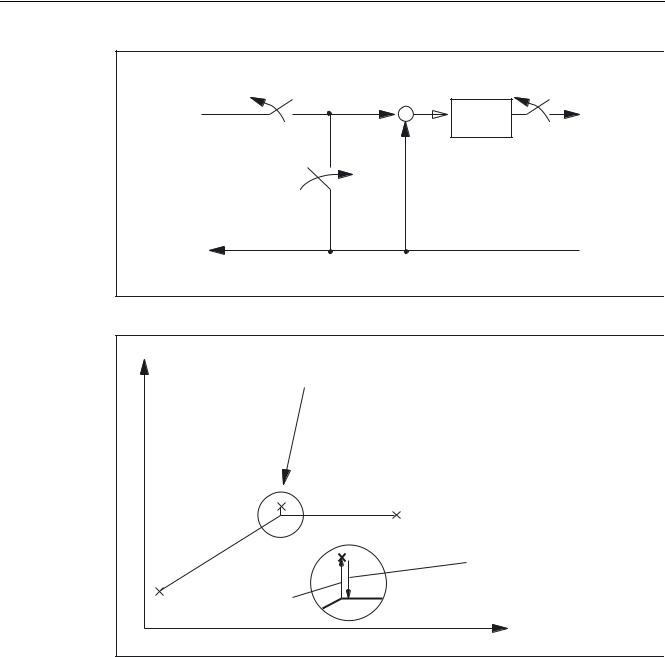
Application example
Positioning response of machine axis Y following clamping when "servo enable" set. Clamping pushed the machine axis from the actual position Y1 to the clamping position Yk.
Various NC/PLC interface signals and functions (A2) |
2-9 |
Function Manual, 03/2006 Edition, 6FC5397-0BP10-1BA0 |
Detailed description
2.1 NC/PLC interface signals
3RVLWLRQ VHWSRLQW IURP ,32
 3RVLWLRQ B FRQWUROOHU
&RQWUROOHU HQDEOH FDQFHOHG
6HWSRLQW IROORZ XS
3RVLWLRQ DFWXDO YDOXH
Figure 2-1 Effect of servo enable and follow-up mode
< |
|
|
|
|
|
|
,6 )ROORZ XS PRGH |
|
|
6HTXHQFH |
5HPRYH ,6 6HUYR HQDEOH |
|
|
|
7HUPLQDOV |
|
|
|
'LVFRQQHFW WHUPLQDOV |
|
|
|
6HW ,6 6HUYR HQDEOH |
|
|
1 |
|
|
<. |
|
|
|
< |
|
|
1 |
|
|
|
|
|
<. |
|
|
|
|
5HWXUQ XVLQJ SRVLWLRQ FRQWUROOHU |
|
|
|
WR SUH FODPSLQJ SRVLWLRQ < |
|
|
|
ZKHQ VHWWLQJ VHUYR HQDEOH |
|
3RVLWLRQ VKLIW |
|
|
|
|
< |
|
UHVXOWLQJ IURP FODPSLQJ |
|
|
|
|
|
|
; |
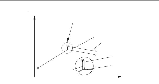
Figure 2-2 Trajectory for clamping and "hold"
2-10 |
Various NC/PLC interface signals and functions (A2) |
Function Manual, 03/2006 Edition, 6FC5397-0BP10-1BA0 |
Detailed description 2.1 NC/PLC interface signals
< |
|
,6 )ROORZ XS PRGH |
6HTXHQFH |
|
5HPRYH ,6 6HUYR HQDEOH |
|
|
7HUPLQDOV |
|
|
'LVFRQQHFW WHUPLQDOV |
|
|
6HW ,6 6HUYR HQDEOH |
|
|
3DWK IROORZHG LI QR SDUW SURJUDP LV DFWLYH |
|
|
7UDMHFWRU\ LI LQ 1 RQO\ ; |
|
|
LV SURJUDPPHG DQG WKH SDUW |
<. |
|
|
|
|
SURJUDP LV DFWLYH |
< |
1 |
|
|
|
5HWXUQ XVLQJ |
|
|
5(326$ LI SDUW SURJUDP LV DFWLYH LQ |
1 |
|
|
|
<. |
|
|
|
$8720$7,& PRGH |
|
|
$[LV PRYHPHQW JHQHUDWHG IURP |
|
|
SURJUDPPHG SRVLWLRQ < |
3RVLWLRQ VKLIW |
|
|
|
< |
|
UHVXOWLQJ IURP FODPSLQJ |
|
|
|
|
; |
Figure 2-3 Trajectory for clamping and "follow-up"
Drives with analog setpoint interface
A drive with an analog setpoint interface is capable of traversing the machine axis with an external setpoint. If "follow-up mode" is set for the machine axis, the actual position continues to be acquired. Once follow-up mode has been cancelled, homing is not required.
The following procedure is recommended:
1.Activate follow-up mode:
DB31, ... DBX2.1 = 0 (servo enable)
DB31, ... DBX1.4 = 1 (follow-up mode) (in the same or preceding OB1 cycle)
→The axis/spindle is operating in followup mode
2.Deactivate external servo enable and external speed setpoint
→Axis/spindle moves with external setpoint
→NC continues to detect the actual position and corrects the setpoint position to the actual position
3.Deactivate external servo enable and cancel external speed setpoint
→Axis/spindle stops
4.Canceling followup mode
DB31, ... DBX2.1 = 1 (servo enable) DB31, ... DBX1.4 = 0 (follow-up mode)
→NC synchronizes to current actual position. The next traversing movement begins at this position.
Various NC/PLC interface signals and functions (A2) |
2-11 |
Function Manual, 03/2006 Edition, 6FC5397-0BP10-1BA0 |

Detailed description
2.1 NC/PLC interface signals
Note
"Followup mode" does not have to be canceled because it only has an effect in combination with "servo enable".
Canceling followup mode
Once follow-up mode has been canceled, the machine axis does not have to be homed again if the maximum permissible encoder limit frequency of the active measuring system was not exceeded during follow-up mode. If the encoder limit frequency is exceeded, the controller will detect this:
•DB31, ... DBX60.4 / 60.5 = 0 (homed/synchronized 1 / 2)
•Alarm: "21610 Encoder frequency exceeded"
Note
If "follow-up mode" is deactivated for a machine axis, which is part of an active transformation (e.g. TRANSMIT), this can generate movements as part of repositioning (REPOS) other machine axes involved in the transformation.
Monitoring
If a machine axis is in follow-up mode, the following monitoring mechanisms will not act:
•Zero-speed monitoring
•Clamping monitoring
•Positioning monitoring
Effects on other interface signals:
•DB31, ... DBX60.7 = 0 (position reached with exact stop fine)
•DB31, ... DBX60.6 = 0 (position reached with exact stop coarse)
DB31, ... DBX1.5 / 1.6 (position measuring system 1 / 2)
2 measuring systems can be connected to one machine axis, e.g.,
•Indirect motor measuring system
•Direct measuring system on load
Only one measuring system can be active at any one time. All closed-loop control, positioning operations, etc. involving the machine axis always relate to the active measuring system.
2-12 |
Various NC/PLC interface signals and functions (A2) |
Function Manual, 03/2006 Edition, 6FC5397-0BP10-1BA0 |
Detailed description 2.1 NC/PLC interface signals
3RVLWLRQ UHIHUHQFH YDOXH |
|
|
|
|
|
|
|
|
IURP |
|
|
|
|
|
|
|
|
|
|
|
|
L6HW |
|
|
|
|
,QWHUSRODWRU |
|
|
|
|
|
|
|
|
|
3RVLWLRQ |
|
6SHHG |
|
3RZHU |
0RWRU |
(QFRG |
(QFRG |
B |
FRQWUROOHU |
B |
FRQWUROOHU |
|
FRQWUROOHU |
|
|
|
|
|
|
|
|
LDFW |
|
|
|
|
|
QDFW |
|
|
|
|
|
|
|
|
|
|
|
|
|
|
|
|
|
|
30 |
|
|
|
|
|
|
|
|
30 |
|
|
|
|
|
30 |
|
|
|
|
|
|
|
|
30 |
|
|
|
|
|
|
|
|
3DUNLQJ D[LV |
|
|
|
|
|
|
|
|
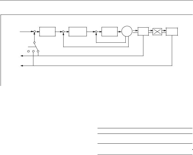
Figure 2-4 Position measuring system 1 and 2
The table below shows the functionality of the interface signals in conjunction with the "servo enable".
DB31, ... DBX1.5 |
DB31, ... DBX1.6 |
DB31, ... DBX2.1 |
Function |
1 |
0 (or 1) |
1 |
Position measuring system 1 active |
0 |
1 |
1 |
Position measuring system 2 active |
0 |
0 |
0 |
"Parking" active |
0 |
0 |
1 |
Spindle without position measuring system (speed- |
|
|
|
controlled) |
1 -> 0 |
0 -> 1 |
1 |
Switchover: Position measuring system 1 → 2 |
0 -> 1 |
1 -> 0 |
1 |
Switchover: Position measuring system 2 → 1 |
DB31, ... DBX2.1 (servo enable)
Setting the servo enable closes the machine axis position control loop. The machine axis is in position control mode.
DB31, ... DBX2.1 == 1
Canceling the servo enable opens the machine axis position control loop and, subject to a delay, the machine axis speed control loop:
DB31, ... DBX2.1 == 0
Various NC/PLC interface signals and functions (A2) |
2-13 |
Function Manual, 03/2006 Edition, 6FC5397-0BP10-1BA0 |

Detailed description
2.1 NC/PLC interface signals
Activation methods
The closed-loop servo enable for a machine axis is influenced by:
•PLC user program by means of the following NC/PLC interface signals:
–DB31, ... DBX2.1 (servo enable)
–DB31, ... DBX21.7 (pulse enable)
–DB31, ... DBX93.5 (drive ready)
–DB10, DBX56.1 (EMERGENCY STOP)
•NCK-internal
Alarms that trigger cancellation of the servo enable on the machine axes. Alarms, which cancel the servo enable, are described in:
References:
/DA/ Diagnostics Manual
Canceling the servo enable when the machine axis is at standstill:
•The machine axis position control loop opens
•DB31, ... DBX61.5 = 0 (position controller active)
Canceling the servo enable when the machine axis is in motion:
If a machine axis is part of an interpolatory path movement or coupling and the servo enable for this is canceled, all axes involved are stopped with a fast stop (speed setpoint = 0) and an alarm is displayed:
Alarm: "21612 Servo enable reset during movement"
•The machine axis is decelerated taking into account the parameterized temporal duration of the brake ramp for error states with a fast stop (speed setpoint = 0):
MD36610 $MA_AX_EMERGENCY_STOP_TIME An alarm is displayed:
Alarm: "21612 Servo enable reset during movement"
Note
The servo enable is canceled at the latest when the cutout time expires: MD36610 $MA_AX_EMERGENCY_STOP_TIME
•The machine axis position control loop opens. Interface signal: DB31, ... DBX61.5 = 0 (position controller active).
The time for the parameterized cut-off delay of the servo enable is started by the machine data:
MD36620 $MA_SERVO_DISABLE_DELAY_TIME.
•As soon as the actual speed has reached the zero speed range, the drive servo enable is canceled. Interface signal:
DB31, ... DBX61.6 = 0 (speed controller active).
2-14 |
Various NC/PLC interface signals and functions (A2) |
Function Manual, 03/2006 Edition, 6FC5397-0BP10-1BA0 |

Detailed description 2.1 NC/PLC interface signals
•The position actual value of the machine axis continues to be acquired by the control.
•At the end of the braking operation, the machine axis is switched to follow-up mode, regardless of the corresponding NC/PLC interface signal. Zero-speed and clamping monitoring are not effective. See the description above for the interface signal:
DB31, ... DBX1.4 (follow-up mode).
Synchronizing the actual value (homing)
Once the servo enable has been set, the actual position of the machine axis does not need to be synchronized again (homing) if the maximum permissible limit frequency of the measuring system was not exceeded during the time in which the machine axis was not in position-control mode.
|
|
3RVLWLRQ FRQWUROOHU |
|
|
RSHQHG LPPHGLDWHO\ |
)S |
|
|
|
|
)SDFW |
|
$[LV LV PRYLQJ |
|
|
|
5DSLG VWRS |
|
|
SRVLWLRQ FRQWURO ORRS |
|
|
)SVHW |
0' 67$1'67,//B9(/2B72/ |
|
|
|
|
W |
|
|
0' $;B(0(5*(1&<B6723B7,0( |
|
,6 6HUYR HQDEOH |
|
|
|
0' 6(592B',6$%/(B'(/$<B7,0( |
|
|
|
|
|
W |
|
,6 3RVLWLRQ FRQWUROOHU DFWLYH |
|
|
|
W |
|
6HUYR HQDEOH WR GULYH |
|
|
,6 6SHHG FRQWUROOHU DFWLYH |
|
|
|
W |
Figure 2-5 Canceling the servo enable when the machine axis is in motion
Various NC/PLC interface signals and functions (A2) |
2-15 |
Function Manual, 03/2006 Edition, 6FC5397-0BP10-1BA0 |

Detailed description
2.1 NC/PLC interface signals
DB31, ... DBX2.2 (Delete distance-to-go/Spindle reset (axis-/spindle-specific))
"Delete distance-to-go" is effective in AUTOMATIC and MDA modes only in conjunction with positioning axes. The positioning axis is decelerated to standstill following the current brake characteristic. The distance-to-go of the axis is deleted.
Spindle reset
A detailed description of the spindle reset can be found in:
References:
/FB1/ Function Manual Basic Functions, Spindles (S1)
DB31, ... DBX9.0 / 9.1 / 9.2 (controller parameter set selection)
The PLC user program sends a binary code request via the "controller parameter set selection" to activate the corresponding parameter set with that of the NC.
DBX9.2 |
DBX9.1 |
DBX9 |
Parameter-set number |
0 |
0 |
0 |
1 |
0 |
0 |
1 |
2 |
0 |
1 |
0 |
3 |
0 |
1 |
1 |
4 |
1 |
0 |
0 |
5 |
1 |
0 |
1 |
6 |
1 |
1 |
0 |
6 |
1 |
1 |
1 |
6 |
Parameter-set changeover must be enabled via the machine data (not required for spindles): MD35590 $MA_PARAMSET_CHANGE_ENABLE = 1 or 2
For detailed information about parameter-set changeover, please refer to:
References:
/FB1/ Function Manual Basic Functions, Spindles (S1) Chapter: Spindle modes > axis mode;
Chapter: Programmable Gears > Gear Stages for Spindles and Gear Change
2-16 |
Various NC/PLC interface signals and functions (A2) |
Function Manual, 03/2006 Edition, 6FC5397-0BP10-1BA0 |
Loading...