


 Loading...
SINUMERIK
SINUMERIK 808D ADVANCED
Parameter Manual
Operating Instructions
08/2013
Preface
Explanation of machine data |
|
|
1 |
||
and setting data |
||
|
|
|
Machine data |
2 |
|
|
|
|
NC setting data |
3 |
|
Detailed descriptions of |
|
|
4 |
||
interface signals |
||
|
|
|
PLC User Interface |
5 |
|
|
|
|
SINAMICS V70 parameters |
6 |
6FC5397-8EP40-0BA0

Legal information Warning notice system
This manual contains notices you have to observe in order to ensure your personal safety, as well as to prevent damage to property. The notices referring to your personal safety are highlighted in the manual by a safety alert symbol, notices referring only to property damage have no safety alert symbol. These notices shown below are graded according to the degree of danger.
 DANGER
indicates that death or severe personal injury will result if proper precautions are not taken.
 WARNING
indicates that death or severe personal injury may result if proper precautions are not taken.
 CAUTION
indicates that minor personal injury can result if proper precautions are not taken.
NOTICE
indicates that property damage can result if proper precautions are not taken.
If more than one degree of danger is present, the warning notice representing the highest degree of danger will be used. A notice warning of injury to personswith a safety alert symbol may also include a warning relating to property damage.
Qualified Personnel
The product/system described in this documentation may be operated only by personnel qualified for the specific task in accordance with the relevant documentation, in particular its warning notices and safety instructions. Qualified personnel are those who, based on their training and experience, are capable of identifying risks and avoiding potential hazards when working with these products/systems.
Proper use of Siemens products
Note the following:
 WARNING
Siemens products may only be used for the applications described in the catalog and in the relevant technical documentation. If products and components from other manufacturers are used, these must be recommended or approved by Siemens. Proper transport, storage, installation, assembly, commissioning, operation and maintenance are required to ensure that the products operate safely and without any problems. The permissible ambient conditions must be complied with. The information in the relevant documentation must be observed.
Trademarks
All names identified by ® are registered trademarks of Siemens AG. The remaining trademarks in this publication may be trademarks whose use by third parties for their own purposes could violate the rights of the owner.
Disclaimer of Liability
We have reviewed the contents of this publication to ensure consistency with the hardware and software described. Since variance cannotbe precludedentirely,wecannotguaranteefullconsistency. However,the informationinthis publication is reviewed regularly and any necessary corrections are included in subsequent editions.
Siemens AG |
Order number: 6FC5397-8EP40-0BA0 |
Copyright © Siemens AG 2012 - 2013. |
Industry Sector |
08.2013 Technical data subject to change |
All rights reserved |
Postfach 48 48 |
|
|
90026 NÜRNBERG |
|
|
GERMANY |
|
|
Table of contents
|
Preface |
......................................................................................................................................................... |
7 |
1 |
Explanation ............................................................................................of machine data and setting data |
9 |
|
|
1.1 .............................................................................................................................. |
Data in the list |
9 |
|
1.2 .................................................................................................................. |
Overview of the data |
15 |
2 |
Machine ............................................................................................................................................data |
17 |
|
|
2.1 ................................................................................................................ |
Display machine data |
17 |
|
2.2 ............................................................................................................... |
General machine data |
28 |
|
2.3 ................................................................................................. |
Channel - specific machine data |
91 |
|
2.4 ...................................................................................................... |
Axis - specific machine data |
192 |
3 |
NC setting .......................................................................................................................................data |
301 |
|
4 |
Detailed ................................................................................................descriptions of interface signals |
329 |
|
|
4.1 ................................................................................................................. |
General information |
329 |
|
4.2 ............................................................................................................................... |
User alarm |
330 |
|
4.3 ............................................................................................................... |
Signals from / to HMI |
331 |
|
4.3.1 ........................................................................................... |
Program control signals from HMI |
331 |
|
4.3.2 ..................................................................................................................... |
Signals from HMI |
334 |
|
4.3.3 ..................................................................................................................... |
Signals from PLC |
335 |
|
4.3.4 .................................................................................................... |
Signals from operator panel |
335 |
|
4.3.5 ............................................................................ |
General selection / status signals from HMI |
336 |
|
4.3.6 ................................................................................ |
General selection / status signals to HMI |
338 |
|
4.4 ............................................................................ |
Auxiliary function transfer from NC channel |
339 |
|
4.5 ............................................................................................................................. |
NCK signals |
342 |
|
4.5.1 ........................................................................................................... |
General signals to NCK |
342 |
|
4.5.2 ....................................................................................................... |
General signals from NCK |
343 |
|
4.6 ........................................................................................................................... |
Mode signals |
345 |
|
4.7 .......................................................................................................... |
Channel - specific signals |
349 |
|
4.7.1 ................................................................................................................... |
Signals to channel |
349 |
|
4.7.2 ......................................................................................................... |
Signals from NC channel |
366 |
|
4.8 .................................................................................................. |
Axis / spindle - specific signals |
376 |
|
4.8.1 .................................................................................. |
Transferred axis - specific M, S functions |
377 |
|
4.8.2 ........................................................................................................... |
Signals to axis / spindle |
378 |
|
4.8.3 ....................................................................................................... |
Signals from axis / spindle |
399 |
5 |
PLC User .................................................................................................................................Interface |
421 |
|
|
5.1 ................................................................................................................... |
Addressing ranges |
421 |
|
5.2 ......................................................................................................................................... |
MCP |
423 |
|
5.2.1 .............................................................................................................. |
Signals from the MCP |
423 |
Parameter Manual |
3 |
Operating Instructions, 08/2013, 6FC5397-8EP40-0BA0 |

Table of contents |
|
|
5.2.2 |
Signals to MCP ........................................................................................................................ |
424 |
5.2.3 |
Reading/writing NC data: Job .................................................................................................. |
425 |
5.2.4 |
Reading/writing NC data: Result .............................................................................................. |
425 |
5.2.5 |
PI service: Job ......................................................................................................................... |
426 |
5.2.6 |
PI service: Result ..................................................................................................................... |
426 |
5.3 |
Retentive data area ................................................................................................................. |
426 |
5.4 |
User Alarms............................................................................................................................. |
427 |
5.4.1 |
User alarms: Activating ............................................................................................................ |
427 |
5.4.2 |
Variables for user alarms ......................................................................................................... |
428 |
5.4.3 |
Active alarm response ............................................................................................................. |
428 |
5.4.4 |
Alarm acknowledgement ......................................................................................................... |
428 |
5.5 |
Signals from/to HMI................................................................................................................. |
429 |
5.5.1 |
Program control signals from the HMI (retentive area) ............................................................ |
429 |
5.5.2 |
Program selection from PLC (retentive area) .......................................................................... |
429 |
5.5.3 |
Checkback signal: Program selection from HMI (retentive area) ............................................ |
430 |
5.5.4 |
Signals from HMI ..................................................................................................................... |
430 |
5.5.5 |
Signals from PLC ..................................................................................................................... |
430 |
5.5.6 |
Signals to maintenance planners ............................................................................................. |
431 |
5.5.7 |
Signals from maintenance planners ........................................................................................ |
432 |
5.5.8 |
Signals from operator panel (retentive area) ........................................................................... |
432 |
5.5.9 |
General selection/status signals from HMI (retentive area) ..................................................... |
432 |
5.5.10 |
General selection/status signals to HMI (retentive area) ......................................................... |
433 |
5.6 |
Auxiliary functions transfer from NC channel........................................................................... |
433 |
5.6.1 |
Overview .................................................................................................................................. |
433 |
5.6.2 |
Decoded M signals (M0 to M99) .............................................................................................. |
434 |
5.6.3 |
Transferred T functions ............................................................................................................ |
435 |
5.6.4 |
Transferred M functions ........................................................................................................... |
435 |
5.6.5 |
Transferred S functions ........................................................................................................... |
435 |
5.6.6 |
Transferred D functions ........................................................................................................... |
436 |
5.6.7 |
Transferred H functions ........................................................................................................... |
436 |
5.7 |
NCK signals............................................................................................................................. |
436 |
5.7.1 |
General signals to NCK ........................................................................................................... |
436 |
5.7.2 |
General signals from NCK ....................................................................................................... |
437 |
5.7.3 |
Signals at fast inputs and outputs ............................................................................................ |
438 |
5.7.4 |
Signals from fast inputs and outputs ........................................................................................ |
439 |
5.8 |
Channel signals....................................................................................................................... |
440 |
5.8.1 |
Signals to NC channel ............................................................................................................. |
440 |
5.8.2 |
Signals from NC channel ......................................................................................................... |
443 |
5.9 |
Axis/spindle signals ................................................................................................................. |
447 |
5.9.1 |
Transferred M and S functions, axis specific ........................................................................... |
447 |
5.9.2 |
Signals to axis/spindle ............................................................................................................. |
447 |
5.9.3 |
Signals from axis/spindle ......................................................................................................... |
450 |
5.10 |
PLC machine data................................................................................................................... |
452 |
5.10.1 |
INT values (MD 14510 USER_DATA_INT) .............................................................................. |
452 |
5.10.2 |
HEX values (MD 14512 USER_DATA_HEX) .......................................................................... |
453 |
5.10.3 FLOAT values (MD 14514 USER_DATA_FLOAT) .................................................................. |
453 |
|
5.10.4 User alarm: Configuring (MD 14516 USER_DATA_PLC_ALARM) ......................................... |
453 |
|
5.11 |
Signals, synchronized actions ................................................................................................. |
454 |
4 |
Parameter Manual |
Operating Instructions, 08/2013, 6FC5397-8EP40-0BA0 |
|
|
|
Table of contents |
|
5.11.1 |
Signals, synchronized actions to channel ................................................................................ |
454 |
|
5.11.2 |
Signals, synchronized actions from channel ........................................................................... |
454 |
|
5.11.3 |
Reading and writing PLC variables ......................................................................................... |
454 |
|
5.12 |
Axis actual values and distance-to-go..................................................................................... |
455 |
|
5.13 |
Maintenance scheduler: User interface................................................................................... |
455 |
|
5.13.1 |
Initial (start) data ...................................................................................................................... |
455 |
|
5.13.2 |
Actual data ............................................................................................................................... |
456 |
|
5.14 |
User interface for ctrl energy............................................................................................ |
....... 456 |
6 |
SINAMICS V70 parameters .................................................................................................................... |
459 |
|
|
6.1 |
Overview................................................................................................................... |
............... 459 |
|
6.2 |
V70 parameters on BOP ...................................................................................................... |
... 460 |
|
6.3 |
Drive basic list on HMI.................................................................................................... |
......... 467 |
|
Index ........................................................................................................................................................ |
|
471 |
Parameter Manual |
5 |
Operating Instructions, 08/2013, 6FC5397-8EP40-0BA0 |

6 |
Parameter Manual |
Operating Instructions, 08/2013, 6FC5397-8EP40-0BA0 |
Preface
Applicable products
This manual is applicable to the following control systems:
Control system |
Software version |
SINUMERIK 808D ADVANCED T (Turning) |
V4.6 |
SINUMERIK 808D ADVANCED M (Milling) |
V4.6 |
Documentation components and target groups
Component |
Recommended target group |
User documentation |
|
Programming and Operating Manual (Turning) |
Programmers and operators of turning machines |
Programming and Operating Manual (Milling) |
Programmers and operators of milling machines |
Programming and Operating Manual (ISO Turning/Milling) |
Programmers and operators of turning/milling machines |
Programming and Operating Manual (Manual Machine Plus |
Programmers and operators of turning machines |
Turning) |
|
Diagnostics Manual |
Mechanical and electrical designers, commissioning |
|
engineers, machine operators, and service and maintenance |
|
personnel |
Manufacturer/service documentation |
|
Commissioning Manual |
Installation personnel, commissioning engineers, and service |
|
and maintenance personnel |
Function Manual |
Mechanical and electrical designers, technical professionals |
Parameter Manual |
Mechanical and electrical designers, technical professionals |
PLC Subroutines Manual |
Mechanical and electrical designers, technical professionals, |
|
and commissioning engineers |
My Documentation Manager (MDM)
Under the following link you will find information to individually compile your documentation based on the Siemens content:
www.siemens.com/mdm
Standard scope
This manual only describes the functionality of the standard version. Extensions or changes made by the machine tool manufacturer are documented by the machine tool manufacturer.
Parameter Manual |
7 |
Operating Instructions, 08/2013, 6FC5397-8EP40-0BA0 |

Preface
Technical support
Hotline: |
|
Service and Support: |
|
• Global support hotline: |
• |
Chinese Web site: |
|
+49 |
(0)911 895 7222 |
|
http://www.siemens.com.cn/808D |
• Support hotline in China: |
• |
Global Web site: |
|
+86 |
4008104288 (china) |
|
http://support.automation.siemens.com |
|
|
|
|
EC Declaration of Conformity
The EC Declaration of Conformity for the EMC Directive can be found on the Internet at http://support.automation.siemens.com
Here, enter the number 15257461 as the search term or contact your local Siemens office.
8 |
Parameter Manual |
Operating Instructions, 08/2013, 6FC5397-8EP40-0BA0 |
Explanation of machine data and setting data |
1 |
|
1.1Data in the list
The machine data and the setting data are listed in form of tables shown below:
MD number |
Identifier |
|
|
Display filter |
Reference |
|
Units |
Name |
|
|
Data type |
Activation |
|
Attributes |
|
|
|
|
|
|
System |
Dimension |
Default value |
Minimum value |
Maximum value |
Protection |
Class |
Expanded table
The expanded table includes data from the standard table plus additional rows with systemspecific values.
MD number |
Identifier |
|
|
Display filter |
Reference |
|
Units |
Name |
|
|
Data type |
Activation |
|
Attributes |
|
|
|
|
|
|
- |
Dimension |
Default value |
Minimum value |
Maximum value |
Protection |
|
<System 1> |
- |
Default value |
- |
- |
-/- |
|
<System 2> |
- |
- |
- |
- |
-1/- |
|
A dash "-" in a field means that the same value as for <System 1> applies for the specified system.
The entry "-/-" in the "Protection" field means that the machine data is not available for the specified system.
Example:
10881 |
MM_EXTERN_GCODE_SYSTEM |
|
N01, N12 |
FBF A |
|
|
- |
ISO_3 Mode: GCodeSystem |
|
DWORD |
Power On |
|
|
- |
|
|
|
|
|
|
808d-te62 |
- |
0 |
0 |
2 |
1/1 |
M |
808d-me62 |
- |
0 |
0 |
2 |
0/0 |
S |
MD number and identifier
MD and SD are addressed via their numbers or their names (identifiers). The number and the name, as well as the activation type and the unit are displayed on the screen of the control system.
In the field "identifier", you can see the name of the data.
Parameter Manual |
9 |
Operating Instructions, 08/2013, 6FC5397-8EP40-0BA0 |

Explanation of machine data and setting data 1.1 Data in the list
Cross reference
For a detailed description of the appropriate data, refer to the description of functions or manual/guide specified.
Attributes
The "Attributes" field contains additional attributes of the data:
Attribute |
Meaning |
NBUP |
No Back UP: The data is not backed up as part of the data backup. |
ODLD |
Only DownLoaD: The data can only be written to via an INI file, archive, or from the part |
|
program. |
NDLD |
No DownLoaD: The data can only be written to via the HMI user interface. |
SFCO |
SaFety COnfiguration: Component of the "Safety Integrated" function |
SCAL |
SCaling ALarm: Scaling data; when changed, alarm 4070 is displayed |
LINK |
LINK description: The data describes a link cluster, component of the "NCU Link" function |
CTEQ |
ConTainer EQual: The data must be the same for all axes in an axis container, component |
|
of the "Axis container" function |
CTDE |
ConTainer DEscription: The data describes an axis container, component of the "Axis |
|
container" function |
Unit/unit system
Depending on MD10240 SCALING_SYSTEM_IS_METRIC, the physical units of the machine data (MD) differ as follows:
MD10240 = 1 |
MD10240 = 0 |
mm |
inch |
mm/min |
inch/min |
m/s2 |
inch/s2 |
m/s3 |
inch/s3 |
mm/rev. |
inch/rev. |
If there are machine data with no physical unit assigned, a hyphen ("-") can be found in the relevant field.
Note
The default setting for MD10240 SCALING_SYSTEM_IS_MERIC is "1".
Dimension
The "Dimension" field contains the number of elements of a data field.
10 |
Parameter Manual |
Operating Instructions, 08/2013, 6FC5397-8EP40-0BA0 |
Explanation of machine data and setting data 1.1 Data in the list
Activation
The control system has defined four activating conditions. Each machine has a corresponding activating condition:
•
•
•
•
PO: Power On (activate by powering on) RE: Reset (activate by pressing RESET key)
CF: Config (activate by pressing vertical softkey "Activate") IM: Immediate (activate immediately after your change)
Display filter
The "Display filter" field contains the identifier of the data filter setting that enables the data to be seen. Using the filter setting, the exact data areas required at a given time can be selected for display.
ID |
Data area |
EXP |
Expert mode |
General machine data |
|
N01 |
Configuration/scaling |
N02 |
Memory configuration |
N03 |
PLC machine data |
N04 |
Drive control |
N05 |
Status data/diagnostics |
N06 |
Monitoring/limiting functions |
N07 |
Auxiliary functions |
N08 |
Corrections/compensations |
N09 |
Technological functions |
N10 |
I/O configuration |
N11 |
Standard machine |
A12 |
NC language, ISO dialect |
Channel machine data |
|
C01 |
Configuration |
C02 |
Memory configuration |
C03 |
Initial states |
C04 |
Auxiliary functions |
C05 |
Velocities |
C06 |
Monitoring/limiting functions |
C07 |
Transformations |
C08 |
Corrections/compensations |
C09 |
Technological functions |
C10 |
Standard machine |
C11 |
NC language, ISO dialect |
Axis machine data
Parameter Manual |
11 |
Operating Instructions, 08/2013, 6FC5397-8EP40-0BA0 |

Explanation of machine data and setting data 1.1 Data in the list
ID |
Data area |
A01 |
Configuration (including memory) |
A02 |
Measuring system |
A03 |
Machine geometry |
A04 |
Velocities / accelerations |
A05 |
Monitoring/limiting functions |
A06 |
Spindle |
A07 |
Controller data |
A08 |
Status data |
A09 |
Corrections/compensations |
A10 |
Technological functions |
A11 |
Standard machine |
A12 |
NC language, ISO dialect |
Data type
In the "Data type" field, the short designators indicate the data types. They have the following meanings:
Designator |
Meaning |
|
BOOLEAN |
Boolean value |
|
|
• |
1: TURE |
|
• |
0: FALSE |
BYTE |
I8-bit value |
|
|
• As an INTEGER value: -128 to 127 |
|
|
• As a hexadecimal value: 00 to FF |
|
|
• As a character as per ASCII character set, e.g. "a" |
|
STRING |
Sequence of characters (max. 16) |
|
WORD |
16-bit value |
|
|
• As an INTEGER value: 0 to 65,535 |
|
|
• As a hexadecimal value: 0000 to FFFF |
|
UNSIGNED WORD |
I16-bit value |
|
|
• As an INTEGRER value: 0 to 65,535 |
|
|
• As a hexadecimal value: 0000 to FFFF |
|
INTEGER |
I16-bit value (here defined locally) |
|
|
• INTEGER value: -32,768 to 32767 |
|
DWORD |
32-bit value |
|
|
• As an INTEGER value: -2,147,483,648 to 2,147,483,647 |
|
|
• As a hexadecimal value: 0000 0000 to FFFF |
|
UNSIGNED DWORD |
I32-bit value |
|
|
• As an INTEGER value: 0 to 4,294,967,295 |
|
|
• As a hexadecimal value: 0000 0000 to FFFF FFFF |
|
DOUBLE |
64-bit value |
|
|
• Floating point value: ±4.19 x 10-307 to ±1.57 x 10308 |
|
12 |
Parameter Manual |
Operating Instructions, 08/2013, 6FC5397-8EP40-0BA0 |
|
|
Explanation of machine data and setting data |
|
|
|
|
|
1.1 Data in the list |
|
|
|
|
Designator |
Meaning |
|
FLOAT DWORD |
Real value: ±7.43 x 10-37 to 3.37 x 1038 |
|
UBYTE |
Integer value: 0 to 255 |
|
LONG |
Integer value: 4,294,967,296 to 4,294,967,295 |
System
Specifies the control system for which the data with the entered values applies.
By default, the entered values apply for both the SINUMERIK 808D ADVANCED Turning and SINUEMRIK 808D ADVANCED Milling.
If no "default" entry exists, the data only apply for the control variants specified:
808d-te62 SINUMERIK 808D ADVANCED Turning
808d-me62 SINUMERIK 808D ADVANCED Milling
Default values
Specifies a default value fort he machine data. If the default values for the channels are different, they are separated with a comma ",".
Range of values (minimum/maximum value)
Specifies the limits for the entered values. If no range of value is specified, the data type determines the input limits, and the field is marked with a dash "-".
Protection
The SINUMERIK 808D ADVANCED provides a concept of access levels for enabling data areas. The access levels correspond with protection levels 0 to 7 (0: the highest level; 7: the lowest level). You can view such information from the table shown as below:
Protection level |
Access level |
Default password |
Target group |
0 |
Siemens |
- |
Reserved for Siemens |
1 |
Manufacturer |
SUNRISE |
OEMs |
2 |
Reserved |
|
|
3 |
Customer |
CUSTOMER |
End users |
4 |
- |
Key-operated switch setting 3 |
End users |
5 |
- |
Key-operated switch setting 2 |
End users |
6 |
- |
Key-operated switch setting 1 |
End users |
7 |
No password |
- |
- |
For the function areas listed below, the input and modification of data depends on the protection level you have set:
•
•
Tool offsets Work offsets
Parameter Manual |
13 |
Operating Instructions, 08/2013, 6FC5397-8EP40-0BA0 |
Explanation of machine data and setting data 1.1 Data in the list
•
•
•
Setting data RS232 settings
Program creation / program correction
You can set the protection levels for these function areas through the following key operations (USER_CLASS...):


 +
+ 

 →
→  →
→  →
→ 
Note
For detailed information about how to set the access levels, refer to the SINUMERIK 808D ADVANCED Programming and Operating Manual (Turning/Milling).
Protection levels: 1, 3
Both of the two access levels require a password.
You can change the password only after an activation with the protection level 1.
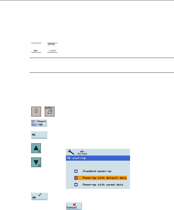
If you forget your password, you can carry out a start-up through the following operations (with the manufacturer password):
1. Select the desired operating area.


 +
+ 


2. Press this softkey to enter the main screen of start-up.
3. Press this softkey to enter the main screen of NC start-up.
4. Use the cursor keys to select the second start-up mode.
5.Press this softkey to confirm your selection, or press the following softkey to cancel:
14 |
Parameter Manual |
Operating Instructions, 08/2013, 6FC5397-8EP40-0BA0 |

Explanation of machine data and setting data 1.2 Overview of the data
This will reset all passwords to their defaults according to the software release you have acquired.
Note
Before performing a start-up with default data, you must backup your data; otherwise, you will have your data lost.
Protection level: 7
If you have deleted your password or do not set a password, you only have the access right of viewing above-mentioned function areas.
Note
The system by default has no password.
1.2Overview of the data
Machine and setting data (SINUMERIK)
The machine and setting data are divided into the following areas:
Range |
Designation |
from 200 to 1200 |
Displaying machine data |
from 10000 to 18999 |
General NC machine data |
from 19000 to 19999 |
Reserved |
from 20000 to 28999 |
Channel-specific machine data |
from 29000 to 29999 |
Reserved |
from 30000 to 38999 |
Axis-specific machine data |
from 39000 to 39999 |
Reserved |
from 41000 to 41999 |
General setting data |
from 42000 to 42999 |
Channel-specific setting data |
from 43000 to 43999 |
Axis-specific setting data |
Data Identifiers
The identifier specified in the data description is displayed on the HMI user interface; however, if the data is addressed in the parts program, for example, the identifier of the relevant data area must precede the data identifier (designator).
Identifier |
Data area |
$MM_ |
Displaying machine data |
$MN_/ $SN_ |
General machine/setting data |
$MNS_/ $SNS_ |
|
Parameter Manual |
15 |
Operating Instructions, 08/2013, 6FC5397-8EP40-0BA0 |

Explanation of machine data and setting data 1.2 Overview of the data
Identifier |
Data area |
$MC_/ $SC_ |
Channel-specific machine/setting data |
$MCS_/ $SCS_ |
|
$MA_/ $SA_ |
Axis-specific machine/setting data |
$MAS_/ $SAS_ |
|
|
|
Characters |
Meanings |
$ |
System variables |
M |
Machine data (first letter) |
S |
Setting data (first letter) |
M, N, C, A, D |
Subarea (second letter) |
S |
Siemens data (third letter) |
Note
Axis-specific data can also be addressed with the axis name as an index. The internal axis identifier (AX1, AX2, AX3, etc.) or the identifier specified in MD10000 $MA_AX_CONF_NAME_TAB can be used as the axis name.
Example: $MA_JOG_VELO[Y1]=2000
The JOG velocity of axis Y1 is 2000 mm/min.
If the content of a machine data is a STRING (e.g., X1) or a hexadecimal value (e.g., H41), the content must be enclosed in single quotation marks (e.g., 'X1' or 'H41').
Example: $MA_FIX_POINT_POS[0,X1]=500.000
The value 500 is assigned to the first fixed point position on axis 1.
Examples: $MN_AUXFU_GROUP_SPEC[2]='H41'
Output instant in time of the auxiliary functions of the 3rd auxiliary function group.
$MN_AXCONF_MACHAX_NAME_TAB[0]='X1'
String "X1" is assigned as name for the first machine axis. $MA_REFP_SET_POS[0,X1]=100.00000
A value of 100 mm is assigned to the first reference point of axis X1.
Examples:
Assignment to channel-specific machine data:
CHANDATA(1) $MC_CHAN_NAME='CHAN1' $MC_AXCONF_GEOAX_NAME_TAB[1]='Y'
;Selection of the first channel
;Name of the first channel
;Name of the 2nd geometry axis
;of the first channel 'Y'
R10=33.75 |
; R10 of the first channel |
16 |
Parameter Manual |
Operating Instructions, 08/2013, 6FC5397-8EP40-0BA0 |
Machine data |
2 |
|
2.1Display machine data
Number |
Identifier |
|
|
Display filters |
Reference |
|
|
|
|
|
|
|
|
Unit |
Name |
|
|
Data type |
Active |
|
|
|
|
|
|
|
|
Attributes |
|
|
|
|
|
|
|
|
|
|
|
|
|
System |
Dimension |
Default value |
Minimum |
Maximum |
Protection |
|
|
|
(LIN/ROT) |
value |
value |
|
|
|
|
|
(LIN/ROT) |
(LIN/ROT) |
|
|
|
|
|
|
|
|
|
Description: |
Description |
|
|
|
|
|
|
|
|
|
|
|
|
1091 |
SINAMICS_IBN_TIMEOUT_VALUE |
|
- |
- |
|
|
|
|
|
|
|||
- |
Wait time when reading in parameters for Sinamics |
DWORD |
Immediately |
|||
|
commissioning |
|
|
|
|
|
|
|
|
|
|
|
|
- |
|
|
|
|
|
|
|
|
|
|
|
|
|
- |
- |
230 |
0 |
1000 |
3/3 |
|
|
|
|
|
|
|
|
Description: Defines the wait time on read-in of the parameters for all SINAMICS devices during commissioning
1092 |
MAX_SPINDEL_SPEED_MANUAL_MA |
|
- |
- |
|
||
|
|
|
|
|
|
||
- |
Input limit spindle speed MM+ |
|
DOUBLE |
Immediately |
|||
|
|
|
|
|
|
|
|
- |
|
|
|
|
|
|
|
|
|
|
|
|
|
|
|
- |
- |
|
99999.00000 |
0 |
99999.00000 |
2/2 |
|
|
|
|
|
|
|
|
|
Description: |
|
Input limit spindle speed MM+ |
|
|
|
||
|
|
|
|
|
|
||
1093 |
MAX_SPEED_G96_MANUAL_MA |
|
- |
- |
|
||
|
|
|
|
|
|||
- |
Input limit cutting meter MM+ |
|
DOUBLE |
Immediately |
|||
|
|
|
|
|
|
|
|
- |
|
|
|
|
|
|
|
|
|
|
|
|
|
|
|
- |
- |
|
99999.00000 |
0 |
99999.00000 |
2/2 |
|
|
|
|
|
|
|
|
|
Description: |
|
Input limit cutting meter MM+ |
|
|
|
||
|
|
|
|
|
|
||
1094 |
MAX_FEEDRATE_G94_MANUAL_MA |
|
- |
- |
|
||
|
|
|
|
|
|||
- |
Input limit time feed MM+ |
|
DOUBLE |
Immediately |
|||
|
|
|
|
|
|
|
|
- |
|
|
|
|
|
|
|
|
|
|
|
|
|
|
|
- |
- |
|
99999.00000 |
0 |
99999.00000 |
2/2 |
|
|
|
|
|
|
|
|
|
Description: |
|
Input limit time feed MM+ |
|
|
|
|
|
|
|
|
|
|
|
||
1095 |
MAX_FEEDRATE_G95_MANUAL_MA |
|
- |
- |
|
||
|
|
|
|
|
|||
- |
Input limit rotation feed MM+ |
|
DOUBLE |
Immediately |
|||
|
|
|
|
|
|
|
|
- |
|
|
|
|
|
|
|
|
|
|
|
|
|
|
|
- |
- |
|
99999.00000 |
0 |
99999.00000 |
2/2 |
|
|
|
|
|
|
|
|
|
Description: |
|
Input limit rotation feed MM+ |
|
|
|
||
Parameter Manual |
17 |
Operating Instructions, 08/2013, 6FC5397-8EP40-0BA0 |

Machine data
2.1 Display machine data
1096 |
MAX_NUM_CYCLE_MANUAL_MA |
|
- |
- |
|
|
|
||
|
|
|
|
|
|
||||
- |
Number of managed masks per cycle in manual mode of MM+ |
DWORD |
Immediately |
|
|
||||
|
|
|
|
|
|
|
|
|
|
- |
|
|
|
|
|
|
|
|
|
|
|
|
|
|
|
|
|
|
|
- |
- |
|
9 |
1 |
9 |
3/3 |
|
|
|
|
|
|
|
|
|
|
|
|
|
Description: |
|
Number of managed masks per cycle in manual mode of MM+ |
|||||||
|
|
|
|
|
|
|
|
||
1097 |
MAX_NUM_CUTT_EDGES_MANUAL_MA |
|
- |
- |
|
|
|
||
|
|
|
|
|
|
||||
- |
Number of managed cutting edges in MM+ |
|
DWORD |
Immediately |
|
|
|||
|
|
|
|
|
|
|
|
|
|
- |
|
|
|
|
|
|
|
|
|
|
|
|
|
|
|
|
|
|
|
- |
- |
|
9 |
1 |
9 |
3/3 |
|
|
|
|
|
|
|
|
|
|
|
|
|
Description: |
|
Number of managed cutting edges in MM+ |
|
|
|
|
|
||
|
|
|
|
|
|
|
|
||
1098 |
INVERT_SPIN_ICON_MANUAL_MA |
|
- |
- |
|
|
|
||
|
|
|
|
|
|||||
- |
The direction of spindle rotation is displayed inverted. |
BOOLEAN |
Immediately |
|
|
||||
|
|
|
|
|
|
|
|
|
|
- |
|
|
|
|
|
|
|
|
|
|
|
|
|
|
|
|
|
|
|
- |
- |
|
1 |
0 |
1 |
3/2 |
|
|
|
|
|
|
|
|
|
|
|
|
|
Description: |
|
The direction of spindle rotation is displayed inverted. |
|||||||
|
|
|
|
|
|
|
|
||
1099 |
USE_FIXPOINT_MANUAL_MA |
|
- |
- |
|
|
|
||
|
|
|
|
|
|
||||
- |
Tool change step MM+ |
|
BOOLEAN |
Immediately |
|
|
|||
|
|
|
|
|
|
|
|
|
|
- |
|
|
|
|
|
|
|
|
|
|
|
|
|
|
|
|
|
|
|
- |
- |
|
1 |
0 |
1 |
3/3 |
|
|
|
|
|
|
|
|
|
|
|
|
|
Description: |
|
Tool change increment MM+: |
|
|
|
|
|
|
|
|
|
The selection field for fixed-point approach is selected or deselected by |
|||||||
|
|
default |
|
|
|
|
|
|
|
|
|
|
|
|
|
|
|
||
1100 |
MEAS_SPIN_ACTIV_MANUAL_MA |
|
- |
- |
|
|
|
||
|
|
|
|
|
|||||
- |
Measuring the tool offset data in the X direction with the |
BOOLEAN |
Immediately |
|
|
||||
|
spindle rotating |
|
|
|
|
|
|
||
|
|
|
|
|
|
|
|
|
|
- |
|
|
|
|
|
|
|
|
|
|
|
|
|
|
|
|
|
|
|
- |
- |
|
1 |
0 |
1 |
3/2 |
|
|
|
|
|
|
|
|
|
|
|
|
|
Description: If the value is 1, the tool offset data can be measured in the X direction with rotating spindle.
1101 |
USER_TOOL_CHG_MANUAL_MA |
|
- |
- |
|
||
|
|
|
|
|
|
||
- |
Tool change step MM+ |
|
BOOLEAN |
Immediately |
|||
|
|
|
|
|
|
|
|
- |
|
|
|
|
|
|
|
|
|
|
|
|
|
|
|
- |
- |
|
1 |
0 |
1 |
3/3 |
|
|
|
|
|
|
|
|
|
Description: |
|
Tool change increment MM+: |
|
|
|
|
|
If the value is 1, input of a tool or cutting edge number is permissible.
1102 |
CYC_TOOLNO_EDTMODE_MANUAL_MA |
|
- |
- |
|
|
|
|
|
|
|
||
- |
Input mode T no. in the cycle screen forms MM+ |
BOOLEAN |
Immediately |
|||
|
|
|
|
|
|
|
- |
|
|
|
|
|
|
|
|
|
|
|
|
|
- |
- |
1 |
0 |
1 |
3/3 |
|
|
|
|
|
|
|
|
Description: |
Input mode T no. in the |
cycle masks MM+: |
|
|
0: |
No T no. input by the operator. T no. is automatically created from |
|
|
SGUD. |
|
|
|
>=1: |
T no. input by |
the operator |
18 |
Parameter Manual |
Operating Instructions, 08/2013, 6FC5397-8EP40-0BA0 |
|
|
|
|
|
|
|
Machine data |
|
|
|
|
|
|
|
|
|
|
|
|
|
|
|
|
2.1 Display machine data |
||
|
|
|
|
|
|
|
|
|
1103 |
TAPPINGCYCLE_MODE_MANUAL_MA |
|
- |
- |
|
|
||
|
|
|
|
|
||||
- |
Preselection cycle type for thread tapping MM+ |
BOOLEAN |
Immediately |
|
||||
|
|
|
|
|
|
|
|
|
- |
|
|
|
|
|
|
|
|
|
|
|
|
|
|
|
|
|
- |
- |
|
1 |
0 |
1 |
3/3 |
|
|
|
|
|
|
|
|
|
|
|
Description: |
Preselection of cycle type on tapping MM+: |
|
|
|
||||
|
|
With compensating chuck |
without compensating chuck |
|||||
|
0 |
CYCLE840 |
|
CYCLE840 |
|
|
|
|
|
1 |
CYCLE840 |
|
CYCLE84 |
|
|
|
|
|
>=2 |
CYCLE840 |
|
not possible |
||||
|
|
|
|
|
|
|
||
1104 |
TOOL_CHG_MANUALMODE_MA |
|
- |
- |
|
|
||
|
|
|
|
|
||||
- |
Enable tool change in the jog function of the MM+ |
BOOLEAN |
Immediately |
|
||||
|
|
|
|
|
|
|
|
|
- |
|
|
|
|
|
|
|
|
|
|
|
|
|
|
|
|
|
- |
- |
|
1 |
0 |
1 |
3/3 |
|
|
|
|
|
|
|
|
|
|
|
Description: |
Tool change enable in the JOG function of the MM+ |
|
|
|
||||
|
|
|
|
|
|
|
||
1105 |
STARTUP_WITH_MMP |
|
- |
- |
|
|
||
|
|
|
|
|
|
|||
- |
Automatic start of the MM+ after power on |
|
BOOLEAN |
PowerOn |
|
|||
|
|
|
|
|
|
|
|
|
- |
|
|
|
|
|
|
|
|
|
|
|
|
|
|
|
|
|
- |
- |
|
1 |
0 |
1 |
3/3 |
|
|
|
|
|
|
|
|
|
|
|
Description: |
Automatic start of MM+ after power ON |
|
|
|
|
|||
|
|
|
|
|
|
|
||
1106 |
SOFTKEY_CENTRE_ADJ |
|
- |
- |
|
|
||
|
|
|
|
|
|
|||
- |
Softkey text is adjusted |
|
BOOLEAN |
PowerOn |
|
|||
|
|
|
|
|
|
|
|
|
- |
|
|
|
|
|
|
|
|
|
|
|
|
|
|
|
|
|
- |
- |
|
1 |
0 |
1 |
3/3 |
|
|
|
|
|
|
|
|
|
|
|
Description: |
Text on the softkeys is justified |
|
|
|
|
|||
|
|
|
|
|
|
|
||
1107 |
AX_LOAD_DISPL |
|
- |
- |
|
|
||
|
|
|
|
|
|
|||
- |
Activate axis utilization display |
|
BOOLEAN |
Immediately |
|
|||
|
|
|
|
|
|
|
|
|
- |
|
|
|
|
|
|
|
|
|
|
|
|
|
|
|
|
|
- |
- |
|
1 |
0 |
1 |
3/3 |
|
|
|
|
|
|
|
|
|
|
|
Description: |
Activate axis utilization display |
|
|
|
|
|||
|
|
|
|
|
|
|
||
1110 |
ENABLE_LADDER_DB_ADDRESSES |
|
- |
- |
|
|
||
|
|
|
|
|
|
|||
- |
DB representation in the PLC ladder viewer |
|
BOOLEAN |
Immediately |
|
|||
|
|
|
|
|
|
|
|
|
- |
|
|
|
|
|
|
|
|
|
|
|
|
|
|
|
|
|
- |
- |
|
1 |
0 |
1 |
7/2 |
|
|
|
|
|
|
|
|
|
|
|
Description: |
DB representation in the PLC ladder viewer |
|
|
|
||||
|
0 - VB representation of the PLC signals |
|
|
|
||||
|
1 - DB representation of the PLC signals |
|
|
|
||||
|
|
|
|
|
|
|
||
1111 |
ENABLE_LADDER_EDITOR |
|
- |
- |
|
|
||
|
|
|
|
|
|
|||
- |
Activate/deactivate PLC ladder editor |
|
BOOLEAN |
Immediately |
|
|||
|
|
|
|
|
|
|
|
|
- |
|
|
|
|
|
|
|
|
|
|
|
|
|
|
|
|
|
- |
- |
|
1 |
0 |
1 |
7/2 |
|
|
|
|
|
|
|
|
|
|
|
Description: |
Activate/deactivate PLC ladder editor |
|
|
|
|
|||
|
0 - No editing functionality for PLC programs |
|
|
|
||||
|
1 - Activate edit functionality for PLC programs |
|
|
|
||||
Parameter Manual |
19 |
Operating Instructions, 08/2013, 6FC5397-8EP40-0BA0 |

Machine data
2.1 Display machine data
203 |
DISPLAY_RESOLUTION |
|
- |
- |
|
|
|
|
|
|
|
|
|
- |
Display resolution for mm dimension system |
|
BYTE |
Immediately |
||
|
|
|
|
|
|
|
- |
|
|
|
|
|
|
|
|
|
|
|
|
|
- |
0 |
3 |
0 |
5 |
3/2 |
|
|
|
|
|
|
|
|
Description: This MD is used to define the number of decimal places of the position display, for linear axes in metric systems, in general for rotary axes.
Spindle positions are treated like rotary axis positions.
The position display is displayed with a max. of 10 characters including signs and decimal places. A positive sign is not displayed.
By default 3 digits are displayed after the decimal point. MD value=3: display resolution = 10-3 [mm] or [degree], Related to:
MD 10200: INT_INCR_PER_MM bzw. MD 10210: INT_INCR_PER_DEG
204 |
DISPLAY_RESOLUTION_INCH |
|
- |
- |
|
|
|
|
|
|
|
||
- |
Display resolution for inch system of measurement |
BYTE |
Immediately |
|||
|
|
|
|
|
|
|
- |
|
|
|
|
|
|
|
|
|
|
|
|
|
- |
0 |
4 |
0 |
5 |
3/2 |
|
|
|
|
|
|
|
|
Description: This MD is used to define the number of decimal places of the position display for linear axes in the inch system of measurement.
The position display is displayed with a max. of 10 characters including signs and decimal places. A positive sign is not displayed.
By default 4 digits are displayed after the decimal point. MD value=4: display resolution = 10-4 [inch]
For rotary axes and spindle positions the display is maintained as in MD 203. Related to:
MD 10200: INT_INCR_PER_MM, MD 203: DISPLAY_RESOLUTION
205 |
DISPLAY_RESOLUTION_SPINDLE |
|
- |
- |
|
|
|
|
|
|
|
|
|
- |
Display resolution for spindle values |
|
BYTE |
Immediately |
||
|
|
|
|
|
|
|
- |
|
|
|
|
|
|
|
|
|
|
|
|
|
- |
0 |
1 |
0 |
5 |
3/2 |
|
|
|
|
|
|
|
|
Description: This MD is used to define the number of decimal places for spindle speed display.
The values are displayed with a max. of 10 characters including sign and decimal point. A positive sign is not displayed.
By default 1 digit is displayed after the decimal point. MD value=1: display resolution = 10-1
207 |
USER_CLASS_READ_TOA |
|
- |
- |
|
|
|
||
|
|
|
|
|
|
|
|||
- |
Read tool offsets protection level, general |
|
BYTE |
Immediately |
|
|
|||
|
|
|
|
|
|
|
|
|
|
- |
|
|
|
|
|
|
|
|
|
|
|
|
|
|
|
|
|
|
|
- |
0 |
|
7 |
0 |
7 |
3/3 |
|
|
|
|
|
|
|
|
|
|
|
|
|
Description: |
|
Protection level of the tool offsets, general |
|
|
|
|
|||
|
|
|
|
|
|
|
|
||
208 |
USER_CLASS_WRITE_TOA_GEO |
|
- |
- |
|
|
|
||
|
|
|
|
|
|
||||
- |
Write tool geometry protection level |
|
BYTE |
Immediately |
|
|
|||
|
|
|
|
|
|
|
|
|
|
- |
|
|
|
|
|
|
|
|
|
|
|
|
|
|
|
|
|
|
|
- |
0 |
|
7 |
0 |
7 |
3/3 |
|
|
|
|
|
|
|
|
|
|
|
|
|
Description: |
|
Protection level for tool offsets (geometry) for writing |
|||||||
20 |
|
|
|
|
|
|
Parameter Manual |
||
|
|
|
|
Operating Instructions, 08/2013, 6FC5397-8EP40-0BA0 |
|||||
|
|
|
|
|
|
|
Machine data |
|
|
|
|
|
|
|
|
|
|
|
|
|
|
|
|
2.1 Display machine data |
||
|
|
|
|
|
|
|
|
|
209 |
USER_CLASS_WRITE_TOA_WEAR |
|
- |
- |
|
|
||
|
|
|
|
|
|
|||
- |
Write tool wear data protection level |
|
BYTE |
Immediately |
|
|||
|
|
|
|
|
|
|
|
|
- |
|
|
|
|
|
|
|
|
|
|
|
|
|
|
|
|
|
- |
0 |
|
7 |
0 |
7 |
3/3 |
|
|
|
|
|
|
|
|
|
|
|
Description: |
|
Protection level of tool offsets (wear) for writing |
||||||
|
|
|
|
|
|
|
||
210 |
USER_CLASS_WRITE_ZOA |
|
- |
- |
|
|
||
|
|
|
|
|
|
|||
- |
Write settable work offset protection level |
|
BYTE |
Immediately |
|
|||
|
|
|
|
|
|
|
|
|
- |
|
|
|
|
|
|
|
|
|
|
|
|
|
|
|
|
|
- |
0 |
|
7 |
0 |
7 |
3/3 |
|
|
|
|
|
|
|
|
|
|
|
Description: |
|
Protection level Settable work offset for writing |
|
|
|
|||
|
|
|
|
|
|
|
||
212 |
USER_CLASS_WRITE_SEA |
|
- |
- |
|
|
||
|
|
|
|
|
|
|||
- |
Protection level write setting data |
|
BYTE |
Immediately |
|
|||
|
|
|
|
|
|
|
|
|
- |
|
|
|
|
|
|
|
|
|
|
|
|
|
|
|
|
|
- |
0 |
|
7 |
0 |
7 |
3/3 |
|
|
|
|
|
|
|
|
|
|
|
Description: |
|
Protection level Setting data for writing |
|
|
|
|||
|
|
|
|
|
|
|
||
213 |
USER_CLASS_READ_PROGRAM |
|
- |
- |
|
|
||
|
|
|
|
|
|
|||
- |
Read protection level of part program |
|
BYTE |
Immediately |
|
|||
|
|
|
|
|
|
|
|
|
- |
|
|
|
|
|
|
|
|
|
|
|
|
|
|
|
|
|
- |
0 |
|
7 |
0 |
7 |
3/3 |
|
|
|
|
|
|
|
|
|
|
|
Description: |
|
Read protection level of part program |
|
|
|
|
||
|
|
|
|
|
|
|
||
214 |
USER_CLASS_WRITE_PROGRAM |
|
- |
- |
|
|
||
|
|
|
|
|
|
|||
- |
Enter part program protection level |
|
BYTE |
Immediately |
|
|||
|
|
|
|
|
|
|
|
|
- |
|
|
|
|
|
|
|
|
|
|
|
|
|
|
|
|
|
- |
0 |
|
7 |
0 |
7 |
3/3 |
|
|
|
|
|
|
|
|
|
|
|
Description: |
|
Enter part program protection level |
|
|
|
|
||
|
|
|
|
|
|
|
||
215 |
USER_CLASS_SELECT_PROGRAM |
|
- |
- |
|
|
||
|
|
|
|
|
|
|||
- |
Program selection protection level |
|
BYTE |
Immediately |
|
|||
|
|
|
|
|
|
|
|
|
- |
|
|
|
|
|
|
|
|
|
|
|
|
|
|
|
|
|
- |
0 |
|
7 |
0 |
7 |
3/3 |
|
|
|
|
|
|
|
|
|
|
|
Description: |
|
Protection level program selection |
|
|
|
|
||
|
|
|
|
|
|
|
||
218 |
USER_CLASS_WRITE_RPA |
|
- |
- |
|
|
||
|
|
|
|
|
|
|||
- |
Protection level write R variables |
|
BYTE |
Immediately |
|
|||
|
|
|
|
|
|
|
|
|
- |
|
|
|
|
|
|
|
|
|
|
|
|
|
|
|
|
|
- |
0 |
|
7 |
0 |
7 |
3/3 |
|
|
|
|
|
|
|
|
|
|
|
Description: |
|
Protection level write R variables |
|
|
|
|
||
|
|
|
|
|
|
|
||
219 |
USER_CLASS_SET_V24 |
|
- |
- |
|
|
||
|
|
|
|
|
|
|||
- |
Set RS-232 protection level |
|
BYTE |
Immediately |
|
|||
|
|
|
|
|
|
|
|
|
- |
|
|
|
|
|
|
|
|
|
|
|
|
|
|
|
|
|
- |
0 |
|
7 |
0 |
7 |
3/3 |
|
|
|
|
|
|
|
|
|
|
|
Description: |
|
Protection level Change parameters for RS-232 interface |
||||||
Parameter Manual |
21 |
Operating Instructions, 08/2013, 6FC5397-8EP40-0BA0 |

Machine data
2.1 Display machine data
221 |
USER_CLASS_DIR_ACCESS |
|
- |
- |
|
||
|
|
|
|
|
|||
- |
Directory access protection level |
|
BYTE |
Immediately |
|||
|
|
|
|
|
|
|
|
- |
|
|
|
|
|
|
|
|
|
|
|
|
|
|
|
- |
0 |
|
7 |
0 |
7 |
3/3 |
|
|
|
|
|
|
|
|
|
Description: |
|
Directory access protection level |
|
|
|
||
|
|
|
|
|
|
||
222 |
USER_CLASS_PLC_ACCESS |
|
- |
- |
|
||
|
|
|
|
|
|||
- |
PLC project protection level |
|
BYTE |
Immediately |
|||
|
|
|
|
|
|
|
|
- |
|
|
|
|
|
|
|
|
|
|
|
|
|
|
|
- |
0 |
|
7 |
0 |
7 |
2/2 |
|
|
|
|
|
|
|
|
|
Description: |
|
PLC project protection level |
|
|
|
||
|
|
|
|
|
|
||
223 |
USER_CLASS_WRITE_PWA |
|
- |
- |
|
||
|
|
|
|
|
|||
- |
Protected work area protection level |
|
BYTE |
Immediately |
|||
|
|
|
|
|
|
|
|
- |
|
|
|
|
|
|
|
|
|
|
|
|
|
|
|
- |
0 |
|
7 |
0 |
7 |
3/2 |
|
|
|
|
|
|
|
|
|
Description: |
|
Protected work area protection level |
|
|
|
||
|
|
|
|
|
|
||
247 |
V24_PG_PC_BAUD |
|
- |
- |
|
||
|
|
|
|
||||
- |
PG: baud rate (300, 600, 1200, 2400, 4800, 9600, 19200, |
BYTE |
Immediately |
||||
|
38400) |
|
|
|
|
|
|
|
|
|
|
|
|
|
|
- |
|
|
|
|
|
|
|
|
|
|
|
|
|
|
|
- |
0 |
|
7 |
5 |
9 |
3/3 |
|
|
|
|
|
|
|
|
|
Description: |
|
PG: baud rate (300, 600, 1200, 2400, 4800, 9600, 19200, 38400) |
|||||
|
|
|
|
|
|
||
280 |
V24_PPI_ADDR_PLC |
|
- |
- |
|
||
|
|
|
|
|
|||
- |
PLC station address |
|
BYTE |
PowerOn |
|||
|
|
|
|
|
|
|
|
- |
|
|
|
|
|
|
|
|
|
|
|
|
|
|
|
- |
- |
|
2 |
0 |
126 |
3/3 |
|
|
|
|
|
|
|
|
|
Description: |
|
PLC station address |
|
|
|
|
|
|
|
|
|
|
|
||
281 |
V24_PPI_ADDR_NCK |
|
- |
- |
|
||
|
|
|
|
|
|||
- |
NCK station address |
|
BYTE |
PowerOn |
|||
|
|
|
|
|
|
|
|
- |
|
|
|
|
|
|
|
|
|
|
|
|
|
|
|
- |
- |
|
3 |
0 |
126 |
3/3 |
|
|
|
|
|
|
|
|
|
Description: |
|
NCK station address |
|
|
|
|
|
|
|
|
|
|
|
||
289 |
CTM_SIMULATION_TIME_NEW_POS |
|
- |
- |
|
||
|
|
|
|
|
|||
- |
Simulation of actual value update rate |
|
BOOLEAN |
Immediately |
|||
|
|
|
|
|
|
|
|
- |
|
|
|
|
|
|
|
|
|
|
|
|
|
|
|
- |
0 |
|
100 |
0 |
4000 |
4/3 |
|
|
|
|
|
|
|
|
|
Description: Use this MD to define the time intervals in which the simulation graphic is updated on the current machine tool machining.
Value = 0 means no update
290 |
CTM_POS_COORDINATE_SYSTEM |
|
- |
- |
|
|
||
|
|
|
|
|
|
|||
- |
Coordinate system position |
|
BYTE |
Immediately |
|
|||
|
|
|
|
|
|
|
|
|
- |
|
|
|
|
|
|
|
|
|
|
|
|
|
|
|
|
|
- |
0 |
|
2 |
0 |
7 |
4/3 |
|
|
|
|
|
|
|
|
|
|
|
Description: |
|
The position of the coordinate system can be changed as follows: |
||||||
22 |
|
|
|
|
|
|
Parameter Manual |
|
|
|
|
|
Operating Instructions, 08/2013, 6FC5397-8EP40-0BA0 |
||||
|
|
|
|
|
|
|
Machine data |
|
|
|
|
|
|
|
|
|
|
|
|
|
|
|
|
2.1 Display machine data |
||
|
|
|
|
|
|
|
|
|
291 |
CTM_CROSS_AX_DIAMETER_ON |
|
- |
- |
|
|
||
|
|
|
|
|
|
|||
- |
Diameter display active for transv. axes |
|
BYTE |
Immediately |
|
|||
|
|
|
|
|
|
|
|
|
- |
|
|
|
|
|
|
|
|
|
|
|
|
|
|
|
|
|
- |
0 |
|
1 |
0 |
1 |
4/3 |
|
|
|
|
|
|
|
|
|
|
|
Description: |
0: Input of absolute values as radius value |
|
|
|
||||
|
Work offsets always in radius |
|
|
|
|
|||
|
Tool lengths always in radius |
|
|
|
|
|||
|
Tool wear always in radius |
|
|
|
|
|
||
|
1: Position display in diameter |
|
|
|
|
|||
|
Distance to go in diameter |
|
|
|
|
|
||
|
Absolute paths in diameter |
|
|
|
|
|
||
|
|
|
|
|
|
|
||
292 |
CTM_G91_DIAMETER_ON |
|
- |
- |
|
|
||
|
|
|
|
|
|
|||
- |
Incremental infeed |
|
BYTE |
Immediately |
|
|||
|
|
|
|
|
|
|
|
|
- |
|
|
|
|
|
|
|
|
|
|
|
|
|
|
|
|
|
- |
0 |
|
1 |
0 |
1 |
7/3 |
|
|
|
|
|
|
|
|
|
|
|
Description: |
0: |
Input in radius |
|
|
|
|
|
|
|
1: |
Input in diameter |
|
|
|
|
|
|
|
|
|
|
|
|
|
|
|
305 |
G_GROUP1 |
|
|
|
- |
- |
|
|
|
|
|
|
|
|
|||
- |
User-oriented G group for position display |
|
BOOLEAN |
Immediately |
|
|||
|
|
|
|
|
|
|
|
|
- |
|
|
|
|
|
|
|
|
|
|
|
|
|
|
|
|
|
- |
0 |
|
1 |
1 |
1000 |
7/3 |
|
|
|
|
|
|
|
|
|
|
|
Description: |
User-oriented G group for position display |
|
|
|
||||
|
|
|
|
|
|
|
|
|
306 |
G_GROUP2 |
|
|
|
- |
- |
|
|
|
|
|
|
|
|
|||
- |
User-oriented G group for position display |
|
BOOLEAN |
Immediately |
|
|||
|
|
|
|
|
|
|
|
|
- |
|
|
|
|
|
|
|
|
|
|
|
|
|
|
|
|
|
- |
0 |
|
2 |
1 |
1000 |
7/3 |
|
|
|
|
|
|
|
|
|
|
|
Description: |
User-oriented G group for position display |
|
|
|
||||
|
|
|
|
|
|
|
|
|
307 |
G_GROUP3 |
|
|
|
- |
- |
|
|
|
|
|
|
|
|
|||
- |
User-oriented G group for position display |
|
BOOLEAN |
Immediately |
|
|||
|
|
|
|
|
|
|
|
|
- |
|
|
|
|
|
|
|
|
|
|
|
|
|
|
|
|
|
- |
0 |
|
8 |
1 |
1000 |
7/3 |
|
|
|
|
|
|
|
|
|
|
|
Description: |
User-oriented G group for position display |
|
|
|
||||
|
|
|
|
|
|
|
|
|
308 |
G_GROUP4 |
|
|
|
- |
- |
|
|
|
|
|
|
|
|
|||
- |
User-oriented G group for position display |
|
BOOLEAN |
Immediately |
|
|||
|
|
|
|
|
|
|
|
|
- |
|
|
|
|
|
|
|
|
|
|
|
|
|
|
|
|
|
- |
0 |
|
9 |
1 |
1000 |
7/3 |
|
|
|
|
|
|
|
|
|
|
|
Description: |
User-oriented G group for position display |
|
|
|
||||
|
|
|
|
|
|
|
|
|
309 |
G_GROUP5 |
|
|
|
- |
- |
|
|
|
|
|
|
|
|
|||
- |
User-oriented G group for position display |
|
BOOLEAN |
Immediately |
|
|||
|
|
|
|
|
|
|
|
|
- |
|
|
|
|
|
|
|
|
|
|
|
|
|
|
|
|
|
- |
0 |
|
10 |
1 |
1000 |
7/3 |
|
|
|
|
|
|
|
|
|
|
|
Description: |
User-oriented G group for position display |
|
|
|
||||
Parameter Manual |
23 |
Operating Instructions, 08/2013, 6FC5397-8EP40-0BA0 |

Machine data
2.1 Display machine data
310 |
FG_GROUP1 |
|
|
- |
- |
|
|
|
|
|
|
||
- |
User-oriented G group for position display (external language) |
BOOLEAN |
Immediately |
|||
|
|
|
|
|
|
|
- |
|
|
|
|
|
|
|
|
|
|
|
|
|
- |
0 |
1 |
1 |
1000 |
7/3 |
|
|
|
|
|
|
|
|
Description: User-oriented G group for position display (ext. language)
311 |
FG_GROUP2 |
|
- |
- |
|
||
|
|
|
|
|
|||
- |
User-oriented G group for position display (external language) |
BOOLEAN |
Immediately |
||||
|
|
|
|
|
|
|
|
- |
|
|
|
|
|
|
|
|
|
|
|
|
|
|
|
- |
0 |
|
2 |
1 |
1000 |
7/3 |
|
|
|
|
|
|
|
|
|
Description: |
|
User-oriented G group for position display (ext. language) |
|||||
|
|
|
|
|
|
||
312 |
FG_GROUP3 |
|
- |
- |
|
||
|
|
|
|
||||
- |
User-oriented G group for position display (external language) |
BOOLEAN |
Immediately |
||||
|
|
|
|
|
|
|
|
- |
|
|
|
|
|
|
|
|
|
|
|
|
|
|
|
- |
0 |
|
8 |
1 |
1000 |
7/3 |
|
|
|
|
|
|
|
|
|
Description: |
|
User-oriented G group for position display (ext. language) |
|||||
|
|
|
|
|
|
||
313 |
FG_GROUP4 |
|
- |
- |
|
||
|
|
|
|
||||
- |
User-oriented G group for position display (external language) |
BOOLEAN |
Immediately |
||||
|
|
|
|
|
|
|
|
- |
|
|
|
|
|
|
|
|
|
|
|
|
|
|
|
- |
0 |
|
9 |
1 |
1000 |
7/3 |
|
|
|
|
|
|
|
|
|
Description: |
|
User-oriented G group for position display (ext. language) |
|||||
|
|
|
|
|
|
||
314 |
FG_GROUP5 |
|
- |
- |
|
||
|
|
|
|
||||
- |
User-oriented G group for position display (external language) |
BOOLEAN |
Immediately |
||||
|
|
|
|
|
|
|
|
- |
|
|
|
|
|
|
|
|
|
|
|
|
|
|
|
- |
0 |
|
19 |
1 |
1000 |
7/3 |
|
|
|
|
|
|
|
|
|
Description: |
|
User-oriented G group for position display (ext. language) |
|||||
|
|
|
|
|
|
||
330 |
CMM_POS_COORDINATE_SYSTEM |
|
- |
- |
|
||
|
|
|
|
|
|||
- |
Coordinate position of the machine axis |
|
BYTE |
Immediately |
|||
|
|
|
|
|
|
|
|
- |
|
|
|
|
|
|
|
|
|
|
|
|
|
|
|
- |
0 |
|
0 |
0 |
7 |
7/3 |
|
|
|
|
|
|
|
|
|
Description: |
|
Coordinate position of the machine |
|
|
|
||
|
|
|
|
|
|
||
331 |
CONTOUR_MASK |
|
- |
- |
|
||
|
|
|
|
|
|||
- |
Enable 802 contour definition programming |
|
BYTE |
Immediately |
|||
|
|
|
|
|
|
|
|
- |
|
|
|
|
|
|
|
|
|
|
|
|
|
|
|
- |
0 |
|
1 |
0 |
1 |
3/3 |
|
|
|
|
|
|
|
|
|
Description: |
|
Enable 802 contour definition programming |
|
|
|||
|
|
|
|
|
|
||
332 |
TOOL_LIST_PLACE_NO |
|
- |
- |
|
||
|
|
|
|
|
|||
- |
Enable the location number in the tool list |
|
BOOLEAN |
Immediately |
|||
|
|
|
|
|
|
|
|
- |
|
|
|
|
|
|
|
|
|
|
|
|
|
|
|
- |
0 |
|
0 |
0 |
1 |
3/3 |
|
|
|
|
|
|
|
|
|
Description: |
|
Enable the location number in the tool list |
|
|
|||
24 |
Parameter Manual |
Operating Instructions, 08/2013, 6FC5397-8EP40-0BA0 |
|
|
|
|
|
|
|
Machine data |
|
|
|
|
|
|
|
|
|
|
|
|
|
|
|
|
2.1 Display machine data |
||
|
|
|
|
|
|
|
|
|
360 |
SPINDEL_LOAD_DISPLE1 |
|
- |
- |
|
|
||
|
|
|
|
|
|
|||
- |
Switch on spindle 1 utilization display |
|
BOOLEAN |
Immediately |
|
|||
|
|
|
|
|
|
|
|
|
- |
|
|
|
|
|
|
|
|
|
|
|
|
|
|
|
|
|
- |
- |
|
0 |
0 |
1 |
3/3 |
|
|
|
|
|
|
|
|
|
|
|
Description: |
|
Switch on spindle 1 utilization display |
|
|
|
|||
|
|
|
|
|
|
|
||
361 |
USER_MEAS_TOOL_CHANGE |
|
- |
- |
|
|
||
|
|
|
|
|
||||
- |
Input enable for T/D no. in tool measuring window |
BYTE |
Immediately |
|
||||
|
|
|
|
|
|
|
|
|
- |
|
|
|
|
|
|
|
|
|
|
|
|
|
|
|
|
|
- |
- |
|
0 |
0 |
1 |
3/3 |
|
|
|
|
|
|
|
|
|
|
|
Description: |
|
0: Input of T/D no. disabled |
|
|
|
|
||
|
|
1: Input of T/D no. enabled |
|
|
|
|
||
|
|
|
|
|
|
|
||
362 |
SPINDLE_LOAD_DISPLE2 |
|
- |
- |
|
|
||
|
|
|
|
|
|
|||
- |
Switch on spindle 2 utilization display |
|
BOOLEAN |
Immediately |
|
|||
|
|
|
|
|
|
|
|
|
- |
|
|
|
|
|
|
|
|
|
|
|
|
|
|
|
|
|
- |
- |
|
1 |
0 |
1 |
3/3 |
|
|
|
|
|
|
|
|
|
|
|
Description: |
|
Switch on spindle 2 utilization display |
|
|
|
|||
|
|
|
|
|
|
|
||
363 |
SPINDLE_LOAD_BAR_LIM2 |
|
- |
- |
|
|
||
|
|
|
|
|
|
|||
- |
Utilization display spindle limit value 2 |
|
BOOLEAN |
Immediately |
|
|||
|
|
|
|
|
|
|
|
|
- |
|
|
|
|
|
|
|
|
|
|
|
|
|
|
|
|
|
- |
- |
|
100 |
0 |
9999999 |
3/3 |
|
|
|
|
|
|
|
|
|
|
|
Description: |
|
Utilization display spindle limit value 2 |
|
|
|
|||
|
|
|
|
|
|
|
||
364 |
SPINDLE_LOAD_BAR_LIM3 |
|
- |
- |
|
|
||
|
|
|
|
|
|
|||
- |
Utilization display spindle limit value 3 |
|
BOOLEAN |
Immediately |
|
|||
|
|
|
|
|
|
|
|
|
- |
|
|
|
|
|
|
|
|
|
|
|
|
|
|
|
|
|
- |
- |
|
100 |
0 |
9999999 |
3/3 |
|
|
|
|
|
|
|
|
|
|
|
Description: |
|
Utilization display spindle limit value 3 |
|
|
|
|||
|
|
|
|
|
|
|
||
365 |
SPINDEL_LOAD_BAR_MAX |
|
- |
- |
|
|
||
|
|
|
|
|
|
|||
- |
Utilization display spindle maximum |
|
BOOLEAN |
Immediately |
|
|||
|
|
|
|
|
|
|
|
|
- |
|
|
|
|
|
|
|
|
|
|
|
|
|
|
|
|
|
- |
- |
|
120 |
0 |
120 |
3/3 |
|
|
|
|
|
|
|
|
|
|
|
Description: |
|
Utilization display spindle maximum |
|
|
|
|
||
|
|
|
|
|
|
|
||
366 |
SPINDEL_LOAD_BAR_COL1 |
|
- |
- |
|
|
||
|
|
|
|
|
|
|||
- |
Color utilization display spindle area 1 |
|
BYTE |
Immediately |
|
|||
|
|
|
|
|
|
|
|
|
- |
|
|
|
|
|
|
|
|
|
|
|
|
|
|
|
|
|
- |
- |
|
10 |
0 |
15 |
3/3 |
|
|
|
|
|
|
|
|
|
|
|
Description: |
|
Color utilization display spindle area 1 |
|
|
|
|||
|
|
|
|
|
|
|
||
367 |
SPINDLE_LOAD_BAR_COL2 |
|
- |
- |
|
|
||
|
|
|
|
|
|
|||
- |
Color utilization display spindle area 2 |
|
BYTE |
Immediately |
|
|||
|
|
|
|
|
|
|
|
|
- |
|
|
|
|
|
|
|
|
|
|
|
|
|
|
|
|
|
- |
- |
|
9 |
0 |
15 |
3/3 |
|
|
|
|
|
|
|
|
|
|
|
Description: |
|
Color utilization display spindle area 2 |
|
|
|
|||
Parameter Manual |
25 |
Operating Instructions, 08/2013, 6FC5397-8EP40-0BA0 |

Machine data
2.1 Display machine data
368 |
SPINDLE_LOAD_BAR_COL3 |
|
- |
- |
|
||
|
|
|
|
|
|||
- |
Color utilization display spindle area 3 |
|
BYTE |
Immediately |
|||
|
|
|
|
|
|
|
|
- |
|
|
|
|
|
|
|
|
|
|
|
|
|
|
|
- |
- |
|
9 |
0 |
15 |
3/3 |
|
|
|
|
|
|
|
|
|
Description: |
|
Color utilization display spindle area 3 |
|
|
|||
|
|
|
|
|
|
||
369 |
PROBE_MODE |
|
- |
- |
|
||
|
|
|
|
||||
- |
Type of measuring system: 1: probe, 2: opt. measuring |
BOOLEAN |
Immediately |
||||
|
procedure |
|
|
|
|
||
|
|
|
|
|
|
|
|
- |
|
|
|
|
|
|
|
|
|
|
|
|
|
|
|
- |
- |
|
1 |
0 |
2 |
3/3 |
|
|
|
|
|
|
|
|
|
Description: |
|
Type of measuring system: 1: probe, 2: opt. measuring procedure |
|||||
|
|
|
|
|
|
||
370 |
TOOL_REF_PROBE_AXIS1 |
|
- |
- |
|
||
|
|
|
|
|
|||
- |
Absolute position probe X |
|
DOUBLE |
Immediately |
|||
|
|
|
|
|
|
|
|
- |
|
|
|
|
|
|
|
|
|
|
|
|
|
|
|
- |
- |
|
0 |
-999999.999 |
999999.999 |
2/2 |
|
|
|
|
|
|
|
|
|
Description: |
|
Absolute position probe X |
|
|
|
|
|
|
|
|
|
|
|
||
371 |
TOOL_REF_PROBE_AXIS2 |
|
- |
- |
|
||
|
|
|
|
|
|||
- |
Absolute position probe Y |
|
DOUBLE |
Immediately |
|||
|
|
|
|
|
|
|
|
- |
|
|
|
|
|
|
|
|
|
|
|
|
|
|
|
- |
- |
|
0 |
-999999.999 |
999999.999 |
2/2 |
|
|
|
|
|
|
|
|
|
Description: |
|
Absolute position probe Y |
|
|
|
|
|
|
|
|
|
|
|
||
372 |
TOOL_REF_PROBE_AXIS3 |
|
- |
- |
|
||
|
|
|
|
|
|||
- |
Absolute position probe Z |
|
DOUBLE |
Immediately |
|||
|
|
|
|
|
|
|
|
- |
|
|
|
|
|
|
|
|
|
|
|
|
|
|
|
- |
- |
|
9 |
-999999.999 |
999999.999 |
2/2 |
|
|
|
|
|
|
|
|
|
Description: |
|
Absolute position probe Z |
|
|
|
|
|
|
|
|
|
|
|
||
374 |
TOOL_WEAR_LIMIT_VALUE |
|
- |
- |
|
||
|
|
|
|
|
|||
- |
Limit value wear control on input |
|
DOUBLE |
Immediately |
|||
|
|
|
|
|
|
|
|
- |
|
|
|
|
|
|
|
|
|
|
|
|
|
|
|
- |
- |
|
9.999 |
0 |
9.999 |
2/2 |
|
|
|
|
|
|
|
|
|
Description: |
|
Limit value wear control on input |
|
|
|
||
|
|
|
|
|
|
||
376 |
USER_CLASS_WRITE_CUS_DIR |
|
- |
- |
|
||
|
|
|
|
|
|||
- |
Write user cycles protection level |
|
BYTE |
Immediately |
|||
|
|
|
|
|
|
|
|
- |
|
|
|
|
|
|
|
|
|
|
|
|
|
|
|
- |
0 |
|
7 |
0 |
7 |
3/3 |
|
|
|
|
|
|
|
|
|
Description: |
|
Protection level User cycles for writing |
|
|
|||
|
|
|
|
|
|
||
377 |
USER_CLASS_WRITE_TO_MON_DAT |
|
- |
- |
|
||
|
|
|
|
|
|||
- |
Tool monitoring protection level |
|
BYTE |
Immediately |
|||
|
|
|
|
|
|
|
|
- |
|
|
|
|
|
|
|
|
|
|
|
|
|
|
|
- |
0 |
|
7 |
0 |
7 |
3/2 |
|
|
|
|
|
|
|
|
|
Description: |
|
Tool monitoring protection level |
|
|
|
||
26 |
Parameter Manual |
Operating Instructions, 08/2013, 6FC5397-8EP40-0BA0 |
|
|
|
|
|
|
|
Machine data |
|
|
|
|
|
|
|
|
|
|
|
|
|
|
|
|
2.1 Display machine data |
||
|
|
|
|
|
|
|
|
|
378 |
USER_CLASS_LADDER_VIEW |
|
- |
- |
|
|
||
|
|
|
|
|
|
|||
- |
Select User Ladder View protection level |
|
BYTE |
Immediately |
|
|||
|
|
|
|
|
|
|
|
|
- |
|
|
|
|
|
|
|
|
|
|
|
|
|
|
|
|
|
- |
0 |
|
2 |
0 |
7 |
2/2 |
|
|
|
|
|
|
|
|
|
|
|
Description: |
|
Select User Ladder View protection level |
|
|
|
|||
|
|
|
|
|
|
|
||
379 |
SPINDLE_DISP_MODE |
|
- |
- |
|
|
||
|
|
|
|
|
|
|||
- |
Spindle display mode |
|
BYTE |
Immediately |
|
|||
|
|
|
|
|
|
|
|
|
- |
|
|
|
|
|
|
|
|
|
|
|
|
|
|
|
|
|
- |
0 |
|
0 |
0 |
2 |
3/3 |
|
|
|
|
|
|
|
|
|
|
|
Description: |
|
0: Standard Mode; spindle speed display |
|
|
|
|||
1:Constant cutting speed display when G96 is set
2:Mixed display
383 |
V24_PPI_ADDR_DRV1 |
|
- |
- |
|
|||
|
|
|
|
|
|
|||
- |
Station address Drives |
|
BYTE |
PowerOn |
||||
|
|
|
|
|
|
|
|
|
- |
|
|
|
|
|
|
|
|
|
|
|
|
|
|
|
|
|
- |
0 |
|
5 |
|
0 |
126 |
3/3 |
|
|
|
|
|
|
|
|
|
|
Description: |
|
Station address Drives |
|
|
|
|
||
|
|
|
|
|
|
|||
386 |
USER_CLASS_WRITE_CMA_DIR |
|
- |
- |
|
|||
|
|
|
|
|||||
- |
Defines the access level for the CMA directory in the NCK |
BYTE |
Immediately |
|||||
|
|
|
|
|
|
|
|
|
- |
|
|
|
|
|
|
|
|
|
|
|
|
|
|
|
|
|
- |
- |
|
7 |
|
1 |
7 |
2/2 |
|
|
|
|
|
|
|
|
|
|
Description: |
|
Defines the access level for the CMA directory in the NCK |
||||||
|
|
|
|
|
|
|||
391 |
DISPLAY_MODE_INDEXING_AXIS |
|
- |
- |
|
|||
|
|
|
|
|
||||
- |
Defines the display format of an indexing axis. |
|
DWORD |
Immediately |
||||
|
|
|
|
|
|
|
|
|
- |
|
|
|
|
|
|
|
|
|
|
|
|
|
|
|
|
|
- |
- |
|
0 |
|
0 |
1 |
7/2 |
|
|
|
|
|
|
|
|
|
|
Description: |
|
Defines the display format of an indexing axis. |
|
|
||||
|
|
0 = indexing position |
|
|
|
|
||
|
|
1 = type-spec. actual value |
|
|
|
|||
|
|
|
|
|
|
|||
392 |
USER_CLASS_WRITE_LOC_NO |
|
- |
- |
|
|||
|
|
|
|
|||||
- |
Access authorization for writing the location number into the |
BYTE |
Immediately |
|||||
|
tool list |
|
|
|
|
|||
|
|
|
|
|
|
|
|
|
- |
|
|
|
|
|
|
|
|
|
|
|
|
|
|
|
|
|
- |
- |
|
7 |
|
0 |
7 |
3/2 |
|
|
|
|
|
|
|
|
|
|
Description: Defines the access authorization for writing the location number in the tool list
395 |
COL_OVERSIZE_TYPE_CHECKBOX |
|
- |
- |
|
||
|
|
|
|
|
|
||
- |
Check box in tool list |
|
BOOLEAN |
Immediately |
|||
|
|
|
|
|
|
|
|
- |
|
|
|
|
|
|
|
|
|
|
|
|
|
|
|
- |
- |
|
1 |
0 |
1 |
3/3 |
|
|
|
|
|
|
|
|
|
Description: |
|
Check box in tool list |
|
|
|
|
|
Parameter Manual |
27 |
Operating Instructions, 08/2013, 6FC5397-8EP40-0BA0 |

Machine data
2.2 General machine data
9000 |
SCREEN_SAVER_WAIT_TIME |
|
- |
- |
|
||
|
|
|
|
|
|
||
s |
The time wait for switch to screen save. |
|
DWORD |
PowerOn |
|||
|
|
|
|
|
|
|
|
- |
|
|
|
|
|
|
|
|
|
|
|
|
|
|
|
- |
- |
|
3600 |
0 |
36000 |
1/1 |
|
|
|
|
|
|
|
|
|
Description: |
|
The time wait for switch to screen save. |
|
|
|||
|
|
|
|
|
|
||
9001 |
TIME_BETWEEN_SLIDES |
|
- |
- |
|
||
|
|
|
|
|
|||
s |
The time between slides show |
|
DWORD |
Immediately |
|||
|
|
|
|
|
|
|
|
- |
|
|
|
|
|
|
|
|
|
|
|
|
|
|
|
- |
- |
|
10 |
1 |
60 |
1/1 |
|
|
|
|
|
|
|
|
|
Description: |
|
The time between slides show |
|
|
|
||
2.2General machine data
Number |
Identifier |
|
|
Display filters |
Reference |
|
|
|
|
|
|
|
|
Unit |
Name |
|
|
Data type |
Active |
|
|
|
|
|
|
|
|
Attributes |
|
|
|
|
|
|
|
|
|
|
|
|
|
System |
Dimension |
Default value |
Minimum |
Maximum |
Protection |
|
|
|
(LIN/ROT) |
value |
value |
|
|
|
|
|
(LIN/ROT) |
(LIN/ROT) |
|
|
|
|
|
|
|
|
|
Description: |
Description |
|
|
|
|
|
28 |
Parameter Manual |
Operating Instructions, 08/2013, 6FC5397-8EP40-0BA0 |
|
|
|
|
|
|
|
Machine data |
|
|
|
|
|
|
|
|
|
|
|
|
|
|
|
|
2.2 General machine data |
||
|
|
|
|
|
|
|
|
|
10000 |
AXCONF_MACHAX_NAME_TAB |
|
N01, N11 |
K2,F1,G2,F2,K5,M1 |
|
|||
|
|
|
|
|
|
|||
- |
Machine axis name |
|
STRING |
PowerOn |
|
|||
|
|
|
|
|
|
|
|
|
- |
|
|
|
|
|
|
|
|
|
|
|
|
|
|
|
|
|
808d-me42 |
4 |
|
MX1, MY1, MZ1, |
- |
- |
2/2 |
|
|
|
|
|
MSP1 |
|
|
|
|
|
|
|
|
|
|
|
|
|
|
808d-me62 |
5 |
|
MX1, MY1, MZ1, |
- |
- |
2/2 |
|
|
|
|
|
MSP1, MA1... |
|
|
|
|
|
|
|
|
|
|
|
|
|
|
808d-te42 |
4 |
|
MX1, MZ1, MSP1, |
- |
- |
2/2 |
|
|
|
|
|
MC1 |
|
|
|
|
|
|
|
|
|
|
|
|
|
|
808d-te62 |
5 |
|
MX1, MZ1, MSP1, |
- |
- |
2/2 |
|
|
|
|
|
MC1 |
|
|
|
|
|
|
|
|
|
|
|
|
|
|
Description: |
|
List of the machine axis identifiers |
|
|
|
|
||
The name of the machine axis is entered in this MD.
In addition to the fixed, defined machine axis identifiers "AX1", "AX2" ..., user-defined identifiers for the machine axes can also be assigned in this data.
The identifiers defined here can be used parallel to the fixed, defined identifiers for addressing axial data (e.g. MD) and machine axis-related NC functions (reference point approach, axial measurement, travel to fixed stop).
Special cases:
•The input machine axis name must not conflict with the names and assignments of the geometry axes (MD20060 $MC_AXCONF_GEOAX_NAME_TAB, MD20050 $MC_AXCONF_GEOAX_ASSIGN_TAB) and channel axes (MD20080 $MC_AXCONF_CHANAX_NAME_TAB, MD20070 $MC_AXCONF_MACHAX_USED).
The input machine axis name must not conflict with Names for Euler angle (MD10620 $MN_EULER_ANGLE_NAME_TAB)
Names for path-relevant orientation (MD10624 $MN_ORIPATH_LIFT_VECTOR_TAB) Names for normal vectors (MD10630 $MN_NORMAL_VECTOR_NAME_TAB)
Names for direction vectors (MD10640 $MN_DIR_VECTOR_NAME_TAB) Names for rotation vectors (MD10642 $MN_ROT_VECTOR_NAME_TAB)
Names for intermediate vector component (MD10644 $MN_INTER_VECTOR_NAME_TAB)
Names for intermediate circle point coordinates for CIP (MD10660 $MN_INTERMEDIATE_POINT_NAME_TAB)
Names for interpolation parameters (MD10650 $MN_IPO_PARAM_NAME_TAB).
•The input machine axis name must not include any of the following reserved address letters:
D Tool offset |
(D function) |
E Reserved |
F V Feedrate |
(F function) |
G Path condition |
H Auxiliary function |
(H function) |
L Subroutine call |
M Miscellaneous function (M function) |
N Subblock |
|
P Subroutine number of passes |
R Arithmetic parameters |
|
S Spindle speed |
(S function) |
T Tool (T function) |
The name must not include any keywords (e.g. DEF, SPOS etc.) or pre-defined identifiers (e.g. ASPLINE, SOFT).
The use of an axis identifier consisting of a valid address letter (A, B, C, I, J, K, Q, U, V, W, X, Y, Z), followed by an optional numerical extension (1-99) gives slightly better block cycle times than a general identifier.
If no identifier is assigned to a machine axis, the predefined name ("AXn") applies to the nth machine axis).
Parameter Manual |
29 |
Operating Instructions, 08/2013, 6FC5397-8EP40-0BA0 |

Machine data
2.2 General machine data
Corresponds with....
MD20060 $MC_AXCONF_GEOAX_NAME_TAB (geometry axis name in the channel [GEOAxisno.]
MD20080 $MC_AXCONF_CHANAX_NAME_TAB (channel axis name in the channel [Channelaxisno.]
10060 |
POSCTRL_SYSCLOCK_TIME_RATIO |
|
N01, N05 |
G3 |
||
|
|
|
|
|
|
|
- |
Factor for position control cycle |
|
DWORD |
PowerOn |
||
|
|
|
|
|
|
|
SFCO |
|
|
|
|
|
|
|
|
|
|
|
|
|
808d-me42 |
- |
2 |
1 |
31 |
7/2 |
|
|
|
|
|
|
|
|
808d-me62 |
- |
1 |
1 |
31 |
7/2 |
|
|
|
|
|
|
|
|
808d-te42 |
- |
2 |
1 |
31 |
7/2 |
|
|
|
|
|
|
|
|
808d-te62 |
- |
1 |
1 |
31 |
7/2 |
|
|
|
|
|
|
|
|
Description: The position-control cycle is stated as a multiple of the time units of the system basic cycle MD10050 $MN_SYSCLOCK_CYCLE_TIME.
For PROFIBUS/PROFINET:
In the case of systems with a PROFIBUS DP connection, this MD represents the ratio between the PROFIBUS DP cycle and the position controller cycle, which is based on the PLC configuration.
10074 |
PLC_IPO_TIME_RATIO |
|
N01, N05 |
- |
|
|
||
|
|
|
|
|
|
|||
- |
Factor of PLC task for the main run. |
|
DWORD |
PowerOn |
|
|||
|
|
|
|
|
|
|
|
|
- |
|
|
|
|
|
|
|
|
|
|
|
|
|
|
|
|
|
- |
- |
|
1 |
1 |
50 |
2/2 |
|
|
|
|
|
|
|
|
|
|
|
Description: |
|
Division ratio between IPO and PLC tasks. |
|
|
|
|||
|
|
A value of 2 means, e. g. that the PLC task is only processed in every second |
||||||
|
|
IPO cycle. The PLC cycle time is then 2 IPO cycle times. This makes more run- |
||||||
|
|
time available for the other tasks. |
|
|
|
|
||
|
|
The PLC run time must not exceed this PLC cycle time, otherwise an alarm with |
||||||
|
|
PLC STOP is triggered. |
|
|
|
|
|
|
|
|
|
|
|
|
|
||
10075 |
PLC_CYCLE_TIME |
|
N01, N05 |
- |
|
|
||
|
|
|
|
|
|
|||
- |
PLC cycle time |
|
DOUBLE |
PowerOn |
|
|||
|
|
|
|
|
|
|
|
|
- |
|
|
|
|
|
|
|
|
|
|
|
|
|
|
|
||
- |
- |
|
0.0 |
- |
- |
ReadOnly |
|
|
|
|
|
|
|
|
|
|
|
Description: |
|
Display of the PLC cycle time (not modifiable, is internally generated) |
||||||
|
|
|
|
|
|
|
||
10127 |
EES_MOUNT_FILE |
|
EXP |
- |
|
|
||
|
|
|
|
|
||||
- |
Path and name of the file with the mounted drives |
STRING |
PowerOn |
|
||||
|
|
|
|
|
|
|
|
|
- |
|
|
|
|
|
|
|
|
|
|
|
|
|
|
|
|
|
- |
- |
|
/user/sinumerik/mnt/ |
- |
- |
1/0 |
|
|
|
|
|
devices.lst |
|
|
|
|
|
|
|
|
|
|
|
|
|
|
Description: File name with path name under which the list of mounted drives is stored.
30 |
Parameter Manual |
Operating Instructions, 08/2013, 6FC5397-8EP40-0BA0 |
Loading...