


s
Training manual
Sinumerik 808D ADVANCED
Programming and Operating Procedures for Milling
Version 2013-09

s
Notes
Operating and Programming — Milling |
Page 2 |
808D ADVANCED |
Basic knowledge of programming for milling is required, before operating of a machine !
Contents
Program
Restart
Pages 65~66 |
Additional
Information
Part 1
Pages 69~75 |
Additional
Information
Part 2
Pages 81~89 |
Preparation
Pages 5~7 |
Machine
Pieces
Pages 61~63 |
Sample
Program
Pages 91~89 |
Switch On and
Referencing
Pages 9~10 |
Test
Program
Pages 57~58 |
ISO Mode
Pages 101~110
Tool Setup
Pages 13~20 |
Simulate
Program
Pages 53~54 |
s
Workpiece
Setup
Pages 23~27 |
Create Part
Program
Part 1
Pages 29~36 |
Create Part
Program
Part 2
Pages 39~51 |
Appendix
Pages 113~116
End
808D ADVANCED |
Page 3 |
Operating and Programming — Milling |

Index |
|
Absolute incremental dimensioning |
32 |
Editing part program |
31 |
Executing M function |
20 |
Calculator |
89 |
Changing time |
78 |
Creating and measuring tools |
13 |
Creating zero offsets |
24 |
Cycles |
40 |
Dry run |
58 |
Jogging spindle |
20 |
Tool wear |
63 |
List of programming functions |
113 |
Manual face milling |
76 |
Manual start spindle |
23 |
s
Manual tool change |
15 |
MDA |
81 |
Moving axis with handwheel |
16 |
Part programming |
29 |
Protection levels |
7 |
Program execution |
57 |
Block search |
65 |
Reference point |
10 |
RS232c and USB |
69 |
Saving data |
78 |
Simulation |
53 |
Subprograms |
82 |
Sample program |
91 |
Timers/counters |
61 |
ISO mode |
101 |
Operating and Programming — Milling |
Page 4 |
808D ADVANCED |
Preparation
Content |
Basic Theory |
s
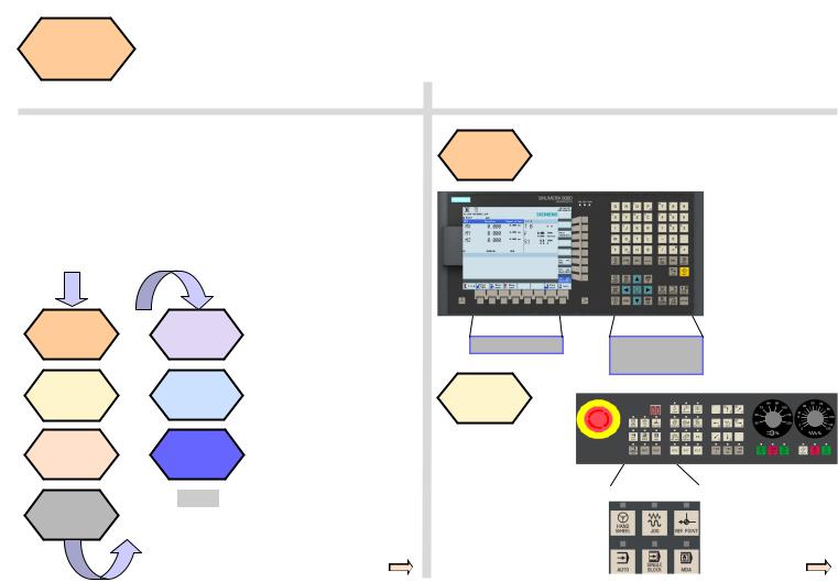
Unit Description
This unit describes the 808D ADVANCED PPU and MCP functionality, the coordinate system of a milling machine and how to enter passwords to access the system.
Unit Content
PPU |
User |
|
Function of |
||
interface |
||
keyboard |
||
|
||
MCP mode |
Machine |
|
coordinate |
||
Changing |
||
system |
||
|
PPU
Function of keyboard
Menu navigation
MCP mode
Changing
The 808D ADVANCED panel processing unit (PPU) is used to input data to the CNC and to navigate to operating areas of the system.
Operating area navigation
MCP |
Passwords |
|
Moving axis |
||
|
||
MCP |
End |
|
|
||
OEM |
|
|
keys |
|
The 808D machine |
Mode Navigation |
control panel (MCP) is |
|
used to select the |
|
machine operating |
|
mode : |
|
JOG - MDA - AUTO |
|
808D ADVANCED |
Page 5 |
Operating and Programming — Milling |
Preparation |
s |
|
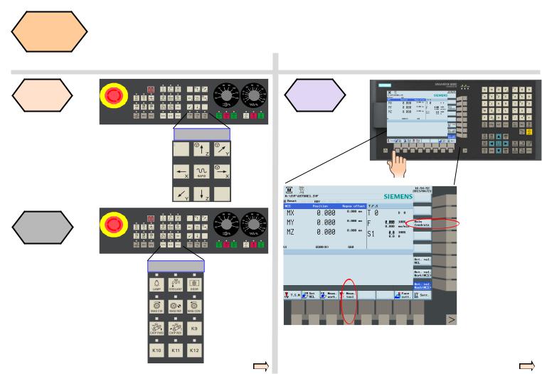
MCP
Moving axis
Axis remove
The 808D
machine control panel (MCP) is used to control manual operation of the axis.
The machine can be moved with the appropriate keys.
MCP OEM keys
OEM keys
The 808D machine control panel (MCP) is used to control OEM machine functions.
The machine functions can be activated with the appropriate keys.
User interface
808D ADVANCED (PPU) has eight vertical softkeys (abbr. SKs) on the right of the screen. These SKs can be activated with the corresponding button (located on the right).
808D ADVANCED (PPU) has eight horizontal SKs on the bottom of the screen. These SKs can be activated with the corresponding button (located below).
Operating and Programming — Milling |
Page 6 |
808D ADVANCED |
Preparation
SEQUENCE
s
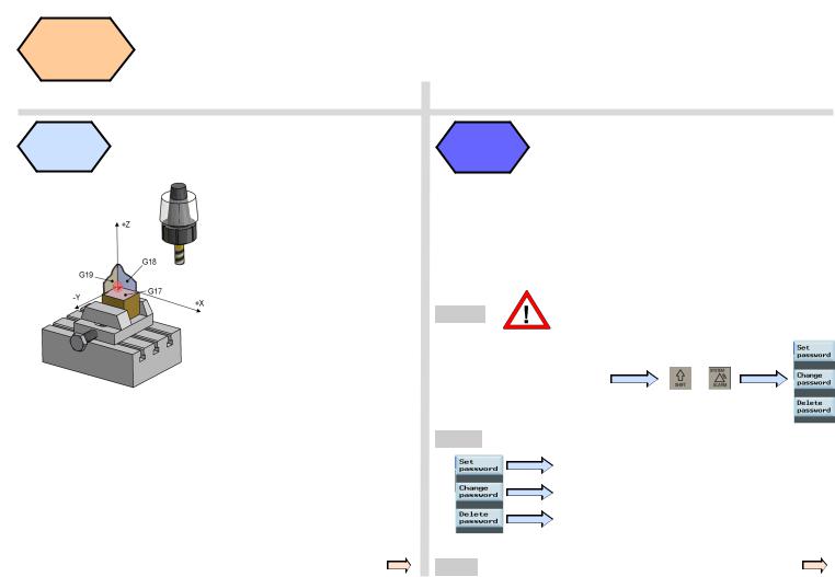
Machine coordinate system
The Sinumerik 808D ADVANCED uses a coordinate system which is derived from the DIN 66217 standard.
The system is an international standard and ensures compatibility between machines and coordinate programming.
The primary function of the coordinate system is to ensure that the tool length and tool radius are calculated correctly in the respective axis.
|
Passwords at the control are used to set the user’s |
|
Passwords |
right to access the system. Tasks such as ”Basic |
|
|
Operating”, “Advanced Operating” and commissioning |
|
|
functions all depend on the passwords. |
|
|
No password |
Machine operator |
|
Customer’s password |
Advanced operator |
|
Manufacturer’s password |
OEM engineer |
|
Customer’s password |
= CUSTOMER |
Changing |
Manufacturer’s password |
= SUNRISE |
|
|
|
password
Step 1 |
Usually the machine, operator does not need |
|
to change the password. |
||
|
The service mode is opened with the appropriate key combination.
In the service mode, the + password can be activated
and deactivated.
Step 2
Enter customer’s or manufacturer’s password
Change customer’s or manufacturer’s password
Delete customer’s or manufacturer’s password
End
808D ADVANCED |
Page 7 |
Operating and Programming — Milling |

s
Notes
Operating and Programming — Milling |
Page 8 |
808D ADVANCED |
Switch On
and
Referencing
Content |
SEQUENCE |
s
Unit Description
This module describes how to switch the machine on and reference it.
Unit Content
Switch on the machine
Reference the machine
End
Switch on the machine
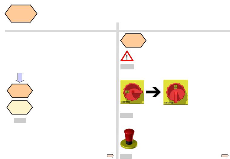
Please note the explicit switching on rules as specified by the machine manufacturer.
Step 1
Turn on the main switch of the machine.
The main switch is usually at the rear of the machine.
Step 2
Make sure you perform the following operation!
Release all the EMERGENCY STOP buttons on the machine!
End
808D ADVANCED |
Page 9 |
Operating and Programming — Milling |
Switch On |
|
|
s |
|
|
and |
|
|
|
Referencing |
|
|
||
|
|
|
||
SEQUENCE |
|
|
|
|
|
|
|
|
|
|
|
|
|
|
Reference |
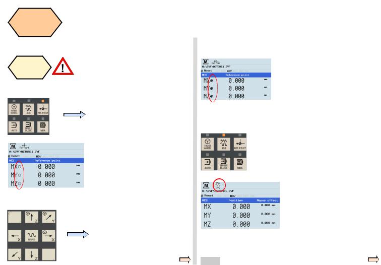
If your machine is configure with ABS |
|
|
|
the |
encoder, you do not need to reference |
|
After completing the referencing |
|
machine |
the axis of the machine. |
|
||
|
procedure for all axes, the refer- |
|||
|
|
If your machine is fitted with INC |
|
|
|
|
|
enced symbol is displayed next to |
|
|
|
encoder, After power on, the machine |
|
|
|
|
|
the axis identifier. |
|
Step 1 |
|
must first be referenced! |
|
|
|
|
|
||
|
|
After power on, the machine will be |
|
|
|
|
in the reference point approach |
|
|
|
|
mode (default). |
|
|
|
|
Step 3 |
|
|
|
|
|
|
|
|
|
|
|
After returning to JOG mode, use |
|
|
If the axis is not referenced, the non- |
|
the axis traversing keys to move the |
|
|
|
machine manually. |
|
|
|
referenced symbol (circle) is dis- |
|
|
|
|
|
|
|
|
|
played between the axis identifier |
|
|
|
|
and the value. |
|
|
|
|
|
|
The machine can now be operated |
|
|
|
|
in JOG mode. |
Step 2 |
|
|
|
|
|
|
|
|
|
|
|
|
|
|
The axes are referenced with the corresponding axis traversing keys.
The traversing direction and keys are specified by the machine manufacturer.
During normal operation (JOG),the referenced symbol is not shown on the screen.
End
Operating and Programming — Milling |
Page 10 |
808D ADVANCED |
s
Notes
808D ADVANCED |
Page 11 |
Operating and Programming — Milling |

s
Notes
Operating and Programming — Milling |
Page 12 |
808D ADVANCED |
Tool Setup
Content |
SEQUENCE |
s
Unit Description
This unit describes how to create and set up tools.
Unit Content
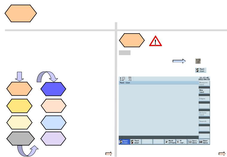
A tool must have been created and Create tool measured before executing the
program.
Step 1 Please make sure the system is in JOG mode.
Press “Offset” on the PPU.
Press the “Tool list” SK on the PPU. 
Create tool |
|
Start |
||
|
spindle |
|||
|
|
|||
Create tool |
|
Measure |
||
edge |
|
tool |
||
Load tool |
|
JOG |
||
into active |
|
|||
|
spindle |
|||
position |
|
|||
|
|
|
||
Move ma- |
Execute M |
|||
chine with |
||||
|
function |
|||
handwheel |
|
|||
|
|
|
||
|
|
|
||
|
|
End |
|
|
|
|
|
|
|
808D ADVANCED |
Page 13 |
Operating and Programming — Milling |
Tool Setup
SEQUENCE
s
|
The range of tool numbers which can be created |
|
Step 2 |
||
by this system is 1 ~32000. |
||
|
||
|
The machine can be loaded with a maximum of |
|
|
64 tools / 128 tool edges. |
|
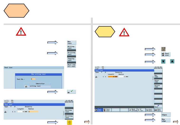
Press the “New tool” SK on the PPU. |
||
Select the type of tool required.
Enter “1” at “Tool No.”
Press the “OK” SK on the PPU.
Enter the ”Radius” of the milling tool.
Press the “Input” button on the PPU.
Create tool A tool must have been created and
|
edge |
selected before creating a tool edge! |
||
|
|
|
||
|
|
Use “D” code to specify the tool edge. The system activates tool |
||
Step 1 |
|
|||
|
edge no. 1 per default at the start. |
|
||
|
|
|
||
Press the “Offset” key on the PPU. |
|
|||
Press the “Tool list” SK on the PPU. |
|
|||
Use direction keys to select the tool |
Or |
|||
which needs to add a tool edge. |
|
|||
|
|
|||
Press the “Edges” SK on the PPU.
Press the “New edge” SK on the PPU.
Operating and Programming — Milling |
Page 14 |
808D ADVANCED |
Tool Setup
SEQUENCE
s
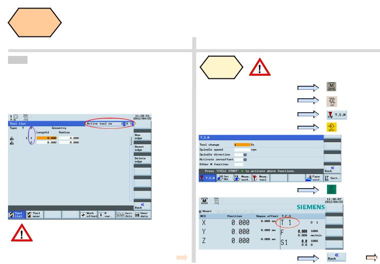
Step 2
A new tool edge can be added in this way and different lengths and radii can be entered as required.
The red circle shows the actual active tool and tool edge,the purple circle shows how many tool edges have been created and the related data for each tool edge.
A maximum of nine tool edges can be created for each tool!
Different tool lengths and radii can be saved in different tool edges as required.
Please select the right tool edge for machining according to requirement! 
Load tool |
A tool must have been created in the |
|
system before it can be loaded into the |
||
into Spindle |
||
active position. |
||
|
Press the “Machine” key on the PPU
Press the “JOG” key on the MCP
Press the “T.S.M” SK on the PPU
Enter tool number “1” in “T”
Press “CYCLE START” on the MCP
Press the “Back” SK on the PPU
808D ADVANCED |
Page 15 |
Operating and Programming — Milling |
Tool Setup |
s |
|
|
||
SEQUENCE |
|
|
|
|
|
|
|
|
The tool are usually loaded manually into the spindle. |
Select the required override increment |
|
|
according to the buttons on the right |
|
The tool will be automatically loaded into the spindle with an automatic tool |
this selection fits all axes |
|
changer. |
||
|
||
|
The handwheel increment is “0.001 mm” |
Move ma- |
Make sure there is no obstruction when |
|
chine with |
moving the tool to avoid a crash. |
|
handwheel |
||
|
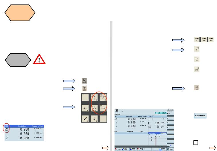
A handwheel can control the axis motion instead of the “JOG” button.
Press the “Machine” key on the PPU
Press the “Handwheel” key on the MCP
Select the axis you want to move with the appropriate keys. on the MCP
Under “WCS” or “MCS” state, a handwheel will be shown beside the axis symbols, showing the axis is chosen, and can be controlled with a handwheel.
The handwheel increment is “0.010 mm” 
The handwheel increment is “0.100 mm” 
The selected axis can now be moved with the handwheel.
Press “JOG” on MCP to end the function of “Handwheel”.
Notes If set the MD14512[16]=80, the system will deactivate the function of MCP for selecting the axis of handwheel, the user will have to activate “Handwheel” function with PPU softkey.
Select the required axis on the right of the PPU; the selected axis is
shown with a √
Operating and Programming — Milling |
Page 16 |
808D ADVANCED |
Tool Setup |
s |
|
SEQUENCE
Start |
A tool must have been loaded and ro- |
|
tated to the position. |
||
spindle |
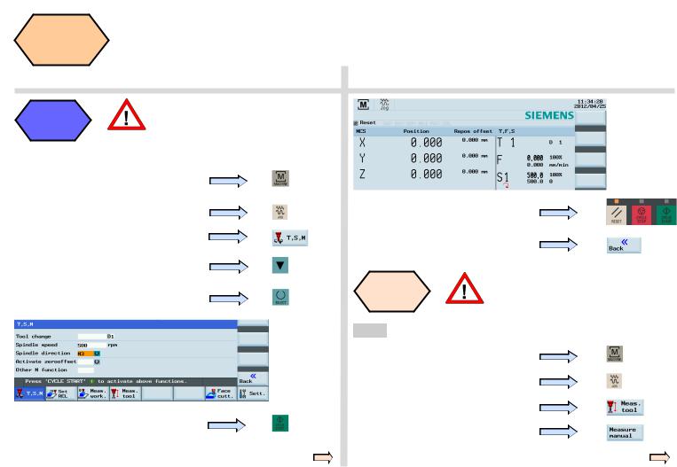
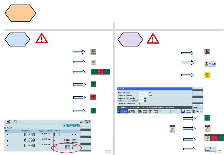
Start the spindle before adjusting tools as follows:
Press the “Machine” key on the PPU
Press the “JOG” key on the MCP
Press the “T.S.M” SK on the PPU
Enter “500” at “Spindle speed”
Select “M3” using the “Select” key on the PPU
Press the “CYCLE START” key on the
MCP
Press “Reset” on the MCP to stop the spindle rotation
Press the “Back” SK on the PPU
Measure |
A tool must have been created and |
tool |
loaded before it can be measured! |
Measure length
Press the “Machine” key on the PPU
Press the “JOG” key on the MCP
Press the “Meas. tool” SK on the PPU
Press the “Measure manual” SK on the
PPU
808D ADVANCED |
Page 17 |
Operating and Programming — Milling |
Tool Setup
SEQUENCE
s
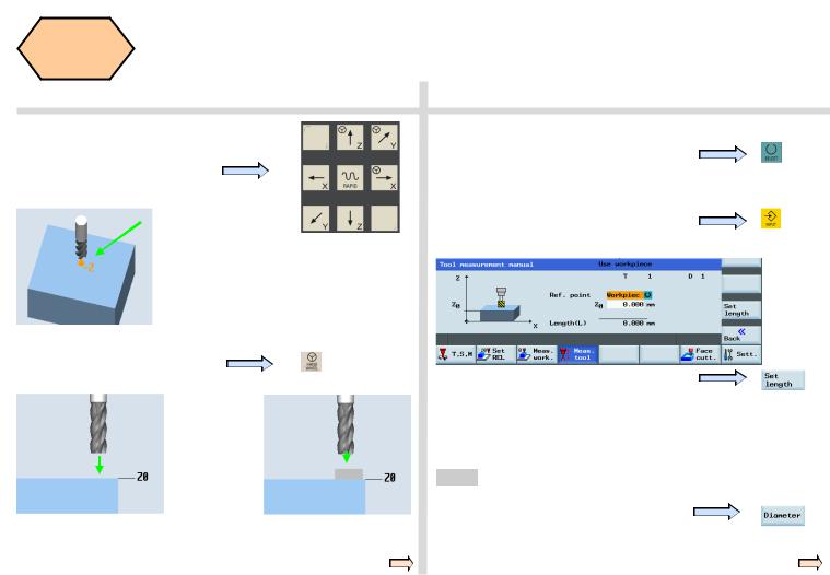
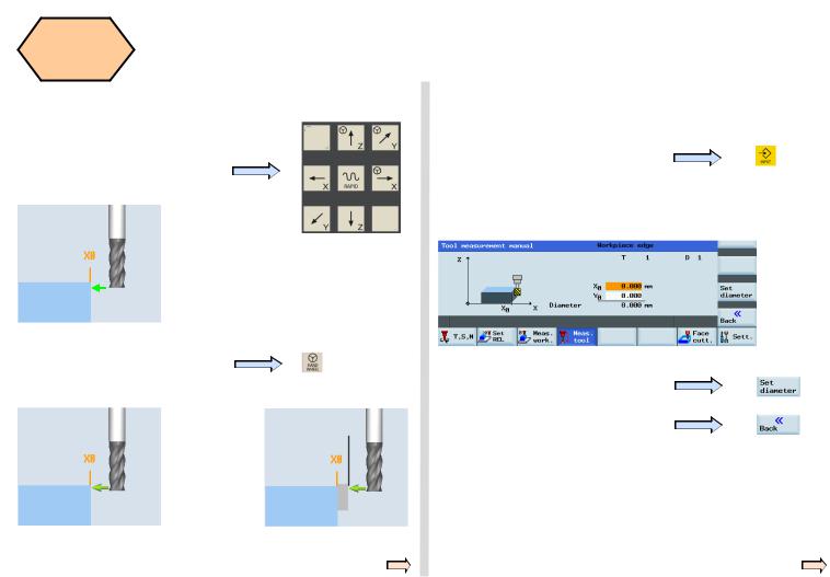
Press the axis keys on the MCP to move the tool to the set position above the workpiece.
Note: The following text describes the required settings in the workpiece coordinate system
“X / Y / Z” zero points as:“X0” / “Y0” / “Z0”
Press the “Handwheel” key on the
MPC and position the tool at location
Z0 or a of the workpiece.
|
or |
a |
|
|
|
|
|||
|
|
|
|
|
Move directly to zero point |
|
Use a setting block. |
||
Use “SELECT” key to set the reference point as “workpiece” (In real measurement, the reference point can be set as either “workpiece” or “ fixed point” if required.
Enter “0” for “Z0”
(If the setting block is used, then the value would be thickness a)
Press the “Set length” SK on the PPU
The measured tool length is now shown in “Length (L)”. This value is also saved in the length value column of the corresponding tool list at the same time.
Step2 Measure diameter
Press the “Diameter” SK on the PPU
Operating and Programming — Milling |
Page 18 |
808D ADVANCED |
Tool Setup |
s |
|
|
SEQUENCE |
|
|
|
|
|
|
Enter “0” at “X0” |
Press the axis keys on the MCP to |
Enter “0” at “Y0” |
(This is the value of the width of a |
|
move the tool to the set position. |
setting block if it is used.Select one of |
|
|
|
X0/Y0 according to requirement.) |
Press the “Handwheel” key on the |
|
|
MCP and position the tool at the |
|
|
location X0 or a of the workpiece. |
|
Press the ”Set diameter” SK on the PPU |
|
|
|
|
a |
Press the “Back” SK on the PPU |
|
|
|
|
or |
|
Move directly to zero point |
Use a setting block. |
|
|
|
808D ADVANCED |
Page 19 |
Operating and Programming — Milling |
Tool Setup
SEQUENCE
s
Jog spindle |
A tool must be loaded to the spindle. |
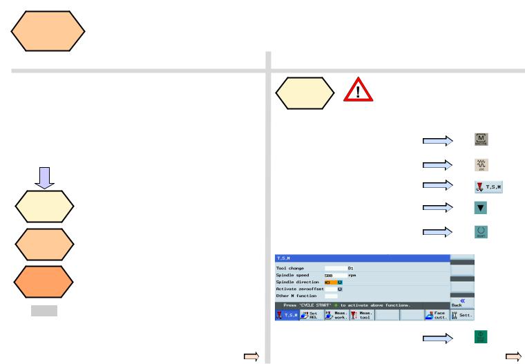
Press the “Machine” key on the PPU.
Press the “JOG” key on the MCP.
Press the spindle direction key on the
MCP to start/stop the spindle.
Press “Spindle left” on the MCP to start the spindle in the counter-clockwise direction.
Press “Spindle stop” on the MCP to stop the spindle.
Press “Spindle right” on the MCP to start the spindle in the clockwise direction.
Please make sure all the machine axes Execute M are in safe positions before executing
function
the M function!
Press the “Machine” key on the PPU.
Press the “T.S.M” SK on the PPU.
Use the direction key to move the highlighted cursor to “Other M function” and enter “8”. This will start the coolant.
Press “CYCLE START” on the MCP.
The coolant function button on
MCP is active.
Press the “Reset” key on the MCP to stop the coolant function.
Press the “Back” SK on the PPU.
Operating and Programming — Milling |
Page 20 |
808D ADVANCED |
s
Notes
808D ADVANCED |
Page 21 |
Operating and Programming — Milling |

s
Notes
Operating and Programming — Milling |
Page 22 |
808D ADVANCED |
Workpiece
Setup
Content |
SEQUENCE |
s
Unit Description
This unit describes how to set the workpiece offset and test the tool results.
Unit Content
Manual start spindle
Create workpiece offset
Test tool offset results
Manual A tool must have been loaded into
start |
the spindle. |
|
spindle |
||
|
Before measuring, the spindle can be started as follows:
Press the “Machine” key on the PPU.
Press the “JOG” key on the MCP.
Press the “T.S.M” SK on the PPU.
Enter “500” in “Spindle speed” on the PPU.
Select “M3” as the “Spindle direction” using the “Select” key on the PPU.
End
Press “CYCLE START” on the MCP.
808D ADVANCED |
Page 23 |
Operating and Programming — Milling |
Workpiece
Setup
SEQUENCE
s
Create |
A tool must have be created and |
workpiece |
measured before it can be used to set |
offset |
the workpiece offset. |
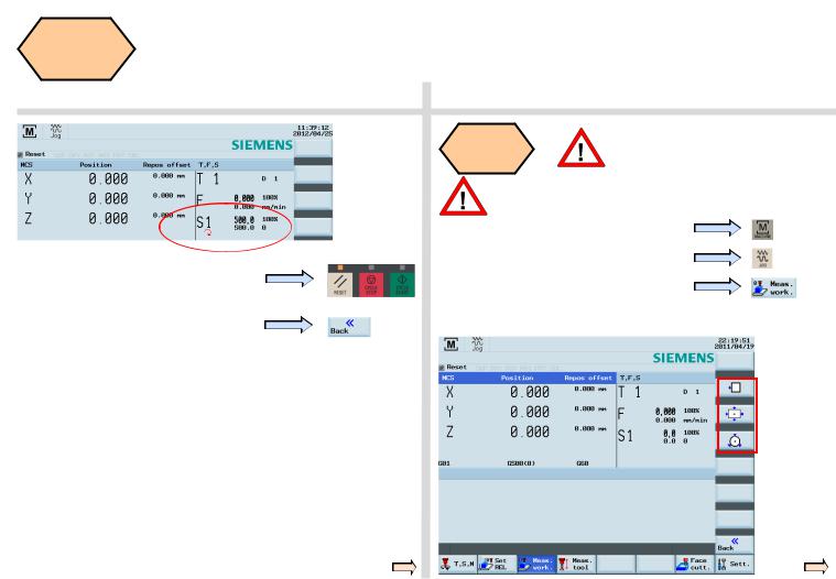
Press the “Reset” key on the MCP to stop the spindle rotation.
Press the “Back” SK on the PPU.
Make sure the active tool is the measured tool!
Press the “Machine” key on the PPU.
Press the “JOG” key on the MCP.
Press the “Meas. work.” SK on the PPU.
As the following red frame shows, 808D ADVANCED provides the user with three methods of using tools to simplify the operating process.
Operating and Programming — Milling |
Page 24 |
808D ADVANCED |
Workpiece
Setup
SEQUENCE
s
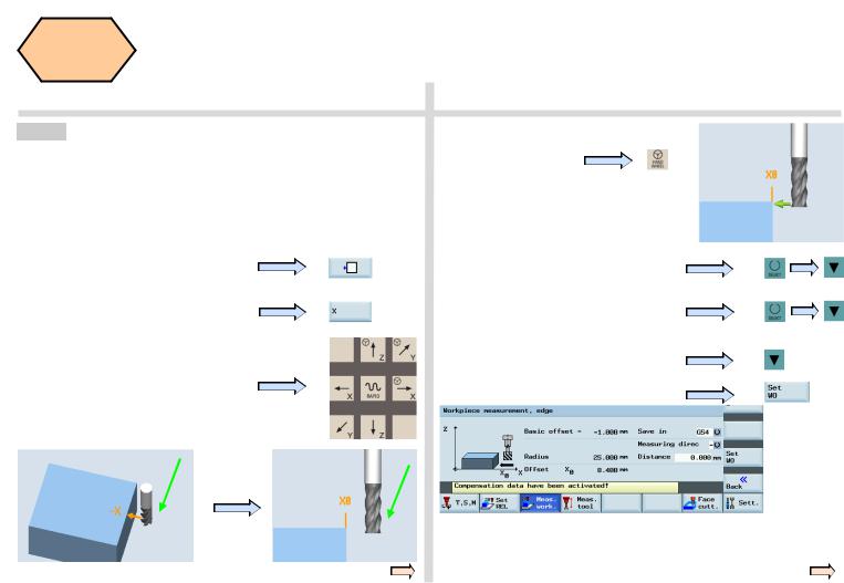
Method1 This method is normally for setting the zero point of the workpiece at the edge of the workpiece.
Using a tool that has a measured “Tool length & radius”, move the tool to a known position on the workpiece. Using either JOG or Handwheel, scratch an edge and then calculate the zero point of the workpiece.
The process of setting the “X” zero point (“X0”) is described below.
Press the corresponding SK of the first icon on the right-hand side of the PPU.
Press the appropriate SK to select the feed axis which needs to be set up.
Press the axis traverse keys to move the tool to the required setting position in the X axis.
Press the “Handwheel” key on the MCP to position the tool at the X0 edge of the workpiece.
Select “Save in” Offset “G54” (or other offset).
Select “Measuring direction” as “-”.
(This value should be chosen according to realities)
Set “Distance” as “0”.
Press the “Set WO” SK on the PPU.
“Step 2” must be repeated for the setting of Y and Z zero points.
If you change the tool because of wear/damage during the machining process, you must remeasure the length of the tool.
808D ADVANCED |
Page 25 |
Operating and Programming — Milling |
Workpiece
Setup
SEQUENCE
s
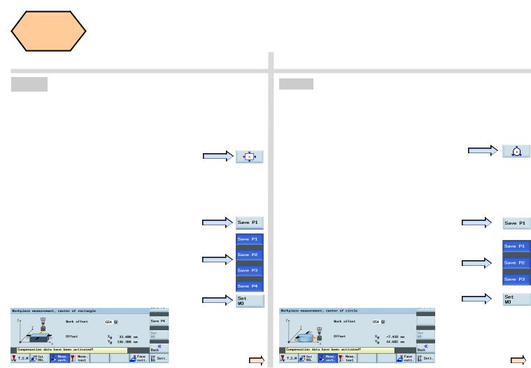
Method 2 This method is normally used for setting the workpiece zero point at the center point of a rectangular workpiece.
Using tools with a measured “length and radius”, move them to the four edges of the rectangular workpiece. Using either JOG or Handwheel, scratch an edge and then calculate the zero point of the workpiece.
Press the corresponding SK of the second icon on the right-hand side of the PPU.
Observing the figure on the PPU, move the coordinate axis following the orange arrow to move the tool to the specified position and scratch the edge of the workpiece.
Press the ”Save P1” SK on the PPU to save the coordinate axis of the 1st position in the system.
Repeat the process for positions 2, 3 and 4. (When the setting is complete, the buttons will be shown in blue.)
Press the “Set WO” SK on the PPU.
You have then finished setting the zero point of the workpiece as the center point of the
rectangular workpiece.
Method 3 This method is normally used for setting the zero points at the center point of a circular workpiece.
Using tools with a measured “length and radius”, move them to the three edges of the circular workpiece. Using either JOG or Handwheel, scratch an edge and then calculate the zero point of the workpiece.
Press the corresponding SK of the third icon on the right-hand side of the PPU.
Observing the figure on the PPU, move the coordinate axis following the orange arrow to move the tool to the specified position and scratch the edge of the workpiece.
Press the ”Save P1” SK on the PPU to save the coordinate axis of the 1st position in the system.
Repeat the process for positions 2 and 3. (When the setting is complete, the buttons will be shown in blue.
Press the “Set WO” SK on the PPU.
You have then finished setting the zero point of the workpiece as the center point of the circular
workpiece.
Operating and Programming — Milling |
Page 26 |
808D ADVANCED |
Workpiece |
s |
|
Setup |
||
SEQUENCE |
|
|
|
|
|
|
|
|
Test tool |
The tool setup and workpiece setup |
|
must have been performed correctly so |
||
offset |
||
results |
that it can be tested as follows! |
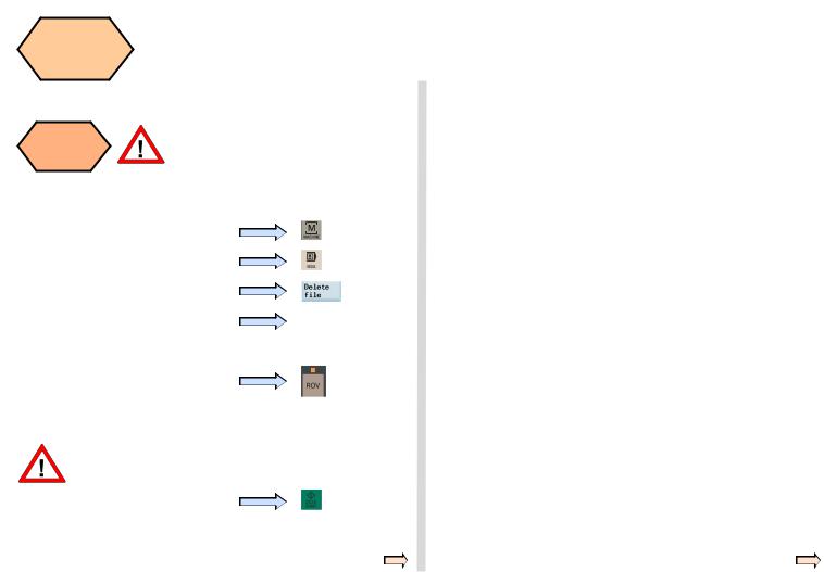
In order to ensure the machine safety and correctness, the results of the tool offset should be tested appropriately.
Press the “Machine” key on the PPU.
Press the “MDA” key on the MCP.
Press the “Delete file” SK on the PPU.
Enter the test program recommended on the right. (can also be customized)
G54 (select offset panel as required)
T1 D1
G00 X0 Y0 Z5
Press the “ROV” key to ensure the
“ROV” function is active (lit up).
Note: The ROV function activates the feedrate override switch under the G00 function.
Make sure the feedrate override on the MCP is at 0%!
Press “CYCLE START” on the MCP.
Increase the feedrate override gradually to avoid accidents caused by an axis moving too fast. Observe whether the axis moves to the set position.
808D ADVANCED |
Page 27 |
Operating and Programming — Milling |

s
Notes
Operating and Programming — Milling |
Page 28 |
808D ADVANCED |
Create Part
Program
Part 1
Content |
Basic Theory |
s
Unit Description
This unit describes how to create a part program, edit the part program and get to know the most important CNC commands required to produce a workpiece.
Unit Content
Program |
Definition |
Milling |
|
of target |
circles and |
||
structure |
|||
position |
arcs |
||
|
|||
Create |
Rapid |
Moving to a |
|
fixed |
|||
program |
motion |
||
position |
|||
|
|
||
Edit |
Tools and |
Controlling |
|
program |
motion |
the spindle |
|
Imperial |
Behaviors |
Setting a |
|
and Metric |
|||
delay in the |
|||
at corners |
|||
system |
|||
program |
|||
|
|||
|
|
||
|
|
End |
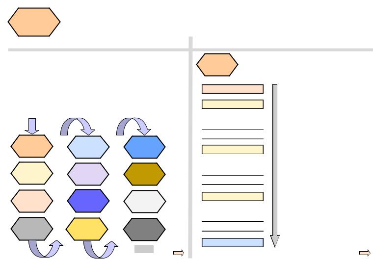
Program
A standard program structure is not needed but is
structure recommended in order to provide clarity for the machine operator. Siemens recommends the
following structure:
Header
T, F, S function
Geometry data / motion
Return to change tool
T, F, S function
Geometry data / motion
Return to change tool
T, F, S function
Geometry data / motion
Return to change tool
End/stop motion
N5 G17 G90 G54 G71
N10 T1 D1 M6
N15 S5000 M3 G94 F300
N20 G00 X100 Y100 Z5
N25 G01 Z-5
N30 Z5
N35 G00 Z500 D0
N40 T2 D1 M6
N45 S3000 M3 G94 F100
N50 G00 X50 Y50 Z5
N55 G01 Z-5
N60 Z5
N65 G00 Z500 D0
N70 T3 D1 M6
N75 S3000 M3 G94 F100
N80 G00 X50 Y50 Z5
N85 G01 Z-5
N90 Z5
N95 G00 Z500 D0
N100 G00 G40 G53 X0 Y0 Z500 D0
M30
808D ADVANCED |
Page 29 |
Operating and Programming — Milling |
Create Part
Program
Part 1
SEQUENCE
s
Create |
The following sequence should be followed to create |
|
a part program: |
||
program |
||
|
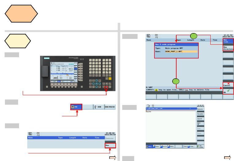
Step 1
Programs can be created with the
“program manager”.
You can select the
“program manager” using the key located on the PPU.
Step 2
Select NC as the storage location for the program. Programs can only be created in the NC.
Step 3
Create a new program with the “New” SK on the right of the PPU.
Step 4 |
1 |
You can choose
“New” or “New directory”.
Choose
“New” to create a program.
2
Choose
“New directory” to create a file.
Step 5
Now the program is opened and can be edited.
The system will save it automatically after editing.
End
Operating and Programming — Milling |
Page 30 |
808D ADVANCED |
 Loading...