


 Loading...
SINUMERIK
SINUMERIK 808D ADVANCED
Programming and Operating Manual (Turning)
User Manual
Legal information
Warning notice system
This manual contains notices you have to observe in order to ensure your personal safety, as well as to prevent damage to property. The notices referring to your personal safety are highlighted in the manual by a safety alert symbol, notices referring only to property damage have no safety alert symbol. These notices shown below are graded according to the degree of danger.
 DANGER
indicates that death or severe personal injury will result if proper precautions are not taken.
 WARNING
indicates that death or severe personal injury may result if proper precautions are not taken.
 CAUTION
indicates that minor personal injury can result if proper precautions are not taken.
NOTICE
indicates that property damage can result if proper precautions are not taken.
If more than one degree of danger is present, the warning notice representing the highest degree of danger will be used. A notice warning of injury to persons with a safety alert symbol may also include a warning relating to property damage.
Qualified Personnel
The product/system described in this documentation may be operated only by personnel qualified for the specific task in accordance with the relevant documentation, in particular its warning notices and safety instructions. Qualified personnel are those who, based on their training and experience, are capable of identifying risks and avoiding potential hazards when working with these products/systems.
Proper use of Siemens products
Note the following:
 WARNING
Siemens products may only be used for the applications described in the catalog and in the relevant technical documentation. If products and components from other manufacturers are used, these must be recommended or approved by Siemens. Proper transport, storage, installation, assembly, commissioning, operation and maintenance are required to ensure that the products operate safely and without any problems. The permissible ambient conditions must be complied with. The information in the relevant documentation must be observed.
© Siemens AG 2014. All rights reserved |
1 |
6FC5398-5DP10-0BA1, 01/2014 |
Preface
Applicable products
This manual is applicable to the following control system:
Control system |
Software version |
SINUMERIK 808D ADVANCED T (Turning) |
V4.6 |
Documentation components and target groups |
|
|
|
Component |
Recommended target group |
User documentation |
|
Programming and Operating Manual (Turning) |
Programmers and operators of turning machines |
Programming and Operating Manual (Milling) |
Programmers and operators of milling machines |
Programming and Operating Manual (ISO Turning/Milling) |
Programmers and operators of turning/milling |
|
machines |
Programming and Operating Manual (Manual Machine Plus Turning) |
Programmers and operators of turning machines |
Diagnostics Manual |
Mechanical and electrical designers, |
|
commissioning engineers, machine operators, |
|
and service and maintenance personnel |
Manufacturer/service documentation |
|
Commissioning Manual |
Installation personnel, commissioning engineers, |
|
and service and maintenance personnel |
Function Manual |
Mechanical and electrical designers, technical |
|
professionals |
Parameter Manual |
Mechanical and electrical designers, technical |
|
professionals |
PLC Subroutines Manual |
Mechanical and electrical designers, technical |
|
professionals, and commissioning engineers |
My Documentation Manager (MDM)
Under the following link you will find information to individually compile your documentation based on the Siemens content: www.siemens.com/mdm
Standard scope
This manual only describes the functionality of the standard version. Extensions or changes made by the machine tool manufacturer are documented by the machine tool manufacturer.
Technical support
Hotline: |
Service and Support: |
||
● |
Global support hotline: |
● |
Chinese Web site: |
|
+49 (0)911 895 7222 |
|
http://www.siemens.com.cn/808D |
● |
Support hotline in China: |
● |
Global Web site: |
|
+86 4008104288 (china) |
|
http://support.automation.siemens.com |
|
|
|
|
EC Declaration of Conformity
The EC Declaration of Conformity for the EMC Directive can be found on the Internet at
http://support.automation.siemens.com
Here, enter the number 15257461 as the search term or contact your local Siemens office.
2 |
Programming and Operating Manual (Turning) |
6FC5398-5DP10-0BA1, 01/2014 |
Table of contents
|
Preface................................................................................................................................................................... |
|
2 |
1 |
Introduction............................................................................................................................................................. |
7 |
|
|
1.1 |
SINUMERIK 808D ADVANCED operator panels.......................................................................................... |
7 |
|
1.1.1 |
Overview ....................................................................................................................................................... |
7 |
|
1.1.2 |
Control elements on the PPU........................................................................................................................ |
8 |
|
1.2 |
Machine control panels ............................................................................................................................... |
10 |
|
1.2.1 |
Overview ..................................................................................................................................................... |
10 |
|
1.2.2 |
Control elements on the MCP ..................................................................................................................... |
11 |
|
1.3 |
Screen layout .............................................................................................................................................. |
13 |
|
1.4 |
Protection levels.......................................................................................................................................... |
14 |
|
1.5 |
Setting user interface language .................................................................................................................. |
15 |
2 |
Turning on, reference point approach .................................................................................................................... |
15 |
|
3 |
Setting-up............................................................................................................................................................. |
|
16 |
|
3.1 |
Coordinate systems .................................................................................................................................... |
16 |
|
3.2 |
Setting up tools ........................................................................................................................................... |
18 |
|
3.2.1 |
Creating a new tool ..................................................................................................................................... |
18 |
|
3.2.2 |
Activating the tool........................................................................................................................................ |
20 |
|
3.2.3 |
Assigning the handwheel ............................................................................................................................ |
20 |
|
3.2.4 |
Activating the spindle .................................................................................................................................. |
22 |
|
3.2.5 |
Measuring the tool (manually)..................................................................................................................... |
22 |
|
3.2.6 |
Verifying the tool offset result in "MDA" mode............................................................................................. |
26 |
|
3.2.7 |
Entering/modifying the tool wear data......................................................................................................... |
27 |
|
3.3 |
Operating area overview............................................................................................................................. |
28 |
4 |
Part programming ................................................................................................................................................. |
29 |
|
|
4.1 |
Creating a part program.............................................................................................................................. |
30 |
|
4.2 |
Editing part programs.................................................................................................................................. |
31 |
|
4.3 |
Managing part programs ............................................................................................................................. |
33 |
5 |
Automatic machining............................................................................................................................................. |
35 |
|
|
5.1 |
Performing the simulation ........................................................................................................................... |
36 |
|
5.2 |
Program control .......................................................................................................................................... |
38 |
|
5.3 |
Program test ............................................................................................................................................... |
39 |
|
5.4 |
Starting and stopping/interrupting a part program....................................................................................... |
41 |
|
5.5 |
Executing/transferring a part program through the RS232 interface ........................................................... |
42 |
|
5.5.1 |
Configuring RS232 communication............................................................................................................. |
42 |
|
5.5.2 |
Executing from external (through RS232 interface) .................................................................................... |
43 |
|
5.5.3 |
Transferring from external (through RS232 interface)................................................................................. |
44 |
|
5.6 |
Machining at a specific point ....................................................................................................................... |
45 |
6 |
Saving system data............................................................................................................................................... |
46 |
|
7 |
Data backup ......................................................................................................................................................... |
48 |
|
8 |
Programming principles ........................................................................................................................................ |
49 |
|
|
8.1 |
Fundamentals of programming ................................................................................................................... |
49 |
|
8.1.1 |
Program names .......................................................................................................................................... |
49 |
|
8.1.2 |
Program structure ....................................................................................................................................... |
49 |
|
8.2 |
Positional data ............................................................................................................................................ |
50 |
|
8.2.1 |
Programming dimensions ........................................................................................................................... |
50 |
Programming and Operating Manual (Turning) |
3 |
||
6FC5398-5DP10-0BA1, 01/2014 |
|||
8.2.2 |
Absolute/incremental dimensioning: G90, G91, AC, IC .............................................................................. |
51 |
8.2.3 |
Dimensions in metric units and inches: G71, G70, G710, G700................................................................. |
52 |
8.2.4 |
Radius/diameter dimensions: DIAMOF, DIAMON, DIAM90 ....................................................................... |
52 |
8.2.5 |
Programmable work offset: TRANS, ATRANS ........................................................................................... |
53 |
8.2.6 |
Programmable scaling factor: SCALE, ASCALE ........................................................................................ |
56 |
8.2.7 |
Workpiece clamping - settable work offset: G54 to G59, G500, G53, G153............................................... |
57 |
8.2.8 |
Kinematic transformation ............................................................................................................................ |
58 |
8.2.8.1 |
Milling on turned parts (TRANSMIT)........................................................................................................... |
58 |
8.2.8.2 |
Cylinder surface transformation (TRACYL) ................................................................................................ |
60 |
8.3 |
Linear interpolation ..................................................................................................................................... |
67 |
8.3.1 |
Linear interpolation with rapid traverse: G0 ................................................................................................ |
67 |
8.3.2 |
Feedrate F .................................................................................................................................................. |
68 |
8.3.3 |
Linear interpolation with feedrate: G1......................................................................................................... |
69 |
8.4 |
Circular interpolation................................................................................................................................... |
70 |
8.4.1 |
Circular interpolation: G2, G3 ..................................................................................................................... |
70 |
8.4.2 |
Circular interpolation via intermediate point: CIP........................................................................................ |
73 |
8.4.3 |
Circle with tangential transition: CT ............................................................................................................ |
73 |
8.5 |
Thread cutting............................................................................................................................................. |
74 |
8.5.1 |
Thread cutting with constant lead: G33 ...................................................................................................... |
74 |
8.5.2 |
Programmable run-in and run-out path for G33: DITS, DITE...................................................................... |
76 |
8.5.3 |
Thread cutting with variable lead: G34, G35............................................................................................... |
77 |
8.5.4 |
Thread interpolation: G331, G332 .............................................................................................................. |
78 |
8.6 |
Fixed point approach .................................................................................................................................. |
79 |
8.6.1 |
Fixed point approach: G75 ......................................................................................................................... |
79 |
8.6.2 |
Reference point approach: G74.................................................................................................................. |
79 |
8.7 |
Acceleration control and exact stop/continuous path.................................................................................. |
80 |
8.7.1 |
Exact stop/continuous-path control mode: G9, G60, G64........................................................................... |
80 |
8.7.2 |
Acceleration pattern: BRISK, SOFT............................................................................................................ |
82 |
8.7.3 |
Dwell Time: G4 ........................................................................................................................................... |
82 |
8.8 |
The third axis .............................................................................................................................................. |
83 |
8.9 |
Spindle movements .................................................................................................................................... |
83 |
8.9.1 |
Spindle speed S, directions of rotation ....................................................................................................... |
83 |
8.9.2 |
Spindle positioning...................................................................................................................................... |
84 |
8.9.2.1 |
Spindle positioning (SPOS, SPOSA, M19, M70, WAITS)........................................................................... |
84 |
8.9.2.2 |
Spindle positioning (SPOS, SPOSA, M19, M70, WAITS): Further information........................................... |
89 |
8.9.3 |
Gear stages ................................................................................................................................................ |
90 |
8.10 |
Special turning functions............................................................................................................................. |
91 |
8.10.1 |
Constant cutting rate: G96, G97 ................................................................................................................. |
91 |
8.10.2 |
Rounding, chamfer ..................................................................................................................................... |
92 |
8.10.3 |
Contour definition programming ................................................................................................................. |
94 |
8.11 |
Tool and tool offset ..................................................................................................................................... |
96 |
8.11.1 |
General information (turning)...................................................................................................................... |
96 |
8.11.2 |
Tool T (turning) ........................................................................................................................................... |
96 |
8.11.3 |
Tool offset number D (turning).................................................................................................................... |
97 |
8.11.4 |
Selecting the tool radius compensation: G41, G42................................................................................... |
100 |
8.11.5 |
Corner behavior: G450, G451 .................................................................................................................. |
102 |
8.11.6 |
Tool radius compensation OFF: G40........................................................................................................ |
102 |
8.11.7 |
Special cases of the tool radius compensation......................................................................................... |
103 |
8.11.8 |
Example of tool radius compensation (turning)......................................................................................... |
104 |
8.11.9 |
Special handling of tool compensation (turning) ....................................................................................... |
105 |
8.12 |
Miscellaneous function M ......................................................................................................................... |
105 |
8.13 |
H function ................................................................................................................................................. |
106 |
8.14 |
Arithmetic parameters, LUD and PLC variables ....................................................................................... |
107 |
8.14.1 |
Arithmetic parameter R............................................................................................................................. |
107 |
8.14.2 |
Local User Data (LUD) ............................................................................................................................. |
108 |
8.14.3 |
Reading and writing PLC variables........................................................................................................... |
109 |
8.15 |
Program jumps ......................................................................................................................................... |
110 |
8.15.1 |
Unconditional program jumps ................................................................................................................... |
110 |
4 |
Programming and Operating Manual (Turning) |
|
|
6FC5398-5DP10-0BA1, 01/2014 |
|
|
8.15.2 |
Conditional program jumps ....................................................................................................................... |
111 |
|
8.15.3 |
Program example for jumps ...................................................................................................................... |
112 |
|
8.15.4 |
Jump destination for program jumps......................................................................................................... |
113 |
|
8.16 |
Subroutine technique ................................................................................................................................ |
113 |
|
8.16.1 |
General information................................................................................................................................... |
113 |
|
8.16.2 |
Calling machining cycles (turning)............................................................................................................. |
115 |
|
8.16.3 |
Executing external subroutines (EXTCALL).............................................................................................. |
116 |
|
8.17 |
Timers and workpiece counters ................................................................................................................ |
117 |
|
8.17.1 |
Runtime timer............................................................................................................................................ |
117 |
|
8.17.2 |
Workpiece counter .................................................................................................................................... |
118 |
9 |
Cycles ................................................................................................................................................................ |
|
120 |
|
9.1 |
Overview of cycles .................................................................................................................................... |
120 |
|
9.2 |
Programming cycles.................................................................................................................................. |
120 |
|
9.3 |
Graphical cycle support in the program editor........................................................................................... |
122 |
|
9.4 |
Drilling cycles ............................................................................................................................................ |
123 |
|
9.4.1 |
General information................................................................................................................................... |
123 |
|
9.4.2 |
Requirements............................................................................................................................................ |
123 |
|
9.4.3 |
Drilling, centering - CYCLE81 ................................................................................................................... |
126 |
|
9.4.4 |
Drilling, counterboring - CYCLE82 ............................................................................................................ |
128 |
|
9.4.5 |
Deep-hole drilling - CYCLE83 ................................................................................................................... |
130 |
|
9.4.6 |
Rigid tapping - CYCLE84 .......................................................................................................................... |
134 |
|
9.4.7 |
Tapping with compensating chuck - CYCLE840 ....................................................................................... |
138 |
|
9.4.8 |
Reaming1 - CYCLE85............................................................................................................................... |
142 |
|
9.4.9 |
Boring - CYCLE86..................................................................................................................................... |
144 |
|
9.4.10 |
Boring with stop 1- CYCLE87 ................................................................................................................... |
147 |
|
9.4.11 |
Drilling with stop 2 - CYCLE88.................................................................................................................. |
148 |
|
9.4.12 |
Reaming 2 - CYCLE89.............................................................................................................................. |
150 |
|
9.5 |
Turning cycles........................................................................................................................................... |
152 |
|
9.5.1 |
Requirements............................................................................................................................................ |
152 |
|
9.5.2 |
Cutoff - CYCLE92 ..................................................................................................................................... |
153 |
|
9.5.3 |
Groove - CYCLE93 ................................................................................................................................... |
155 |
|
9.5.4 |
Undercut (forms E and F to DIN) - CYCLE94 ........................................................................................... |
163 |
|
9.5.5 |
Cutting with relief cut - CYCLE95.............................................................................................................. |
166 |
|
9.5.6 |
Thread undercut - CYCLE96..................................................................................................................... |
181 |
|
9.5.7 |
Thread chaining - CYCLE98 ..................................................................................................................... |
184 |
|
9.5.8 |
Thread cutting - CYCLE99 ........................................................................................................................ |
189 |
|
9.6 |
Error messages and error handling........................................................................................................... |
197 |
|
9.6.1 |
General Information .................................................................................................................................. |
197 |
|
9.6.2 |
Error handling in the cycles....................................................................................................................... |
197 |
|
9.6.3 |
Overview of cycle alarms .......................................................................................................................... |
197 |
|
9.6.4 |
Messages in the cycles ............................................................................................................................. |
197 |
10 |
Typical turning program ...................................................................................................................................... |
198 |
|
A |
Appendix ............................................................................................................................................................ |
|
204 |
|
A.1 |
Creating a new cutting edge ..................................................................................................................... |
204 |
|
A.2 |
Setting up the workpiece........................................................................................................................... |
205 |
|
A.2.1 |
Entering/modifying work offsets ................................................................................................................ |
206 |
|
A.3 |
Entering/modifying the setting data........................................................................................................... |
207 |
|
A.4 |
Setting R parameters ................................................................................................................................ |
209 |
|
A.5 |
Setting user data....................................................................................................................................... |
210 |
|
A.6 |
Other settings in "JOG" mode ................................................................................................................... |
211 |
|
A.6.1 |
Setting the relative coordinate system (REL) ............................................................................................ |
212 |
|
A.6.2 |
Setting the JOG data................................................................................................................................. |
212 |
|
A.7 |
The help system........................................................................................................................................ |
213 |
|
A.8 |
Operation wizard....................................................................................................................................... |
215 |
Programming and Operating Manual (Turning) |
5 |
||
6FC5398-5DP10-0BA1, 01/2014 |
|||
A.9 |
Editing Chinese characters....................................................................................................................... |
216 |
A.10 |
Pocket calculator ...................................................................................................................................... |
217 |
A.11 |
Calculating contour elements ................................................................................................................... |
218 |
A.12 |
Free contour programming ....................................................................................................................... |
222 |
A.12.1 |
Programming a contour ............................................................................................................................ |
223 |
A.12.2 |
Defining a start point................................................................................................................................. |
224 |
A.12.3 |
Programming contour element ................................................................................................................. |
225 |
A.12.4 |
Parameters for contour elements.............................................................................................................. |
227 |
A.12.5 |
Undercuts for turning technology.............................................................................................................. |
230 |
A.12.6 |
Specifying contour elements in polar coordinates..................................................................................... |
231 |
A.12.7 |
Cycle support............................................................................................................................................ |
233 |
A.12.8 |
Programming example for turning application .......................................................................................... |
233 |
A.13 |
Word structure and address ..................................................................................................................... |
237 |
A.14 |
Character set ............................................................................................................................................ |
238 |
A.15 |
Block format.............................................................................................................................................. |
238 |
A.16 |
List of instructions..................................................................................................................................... |
240 |
6 |
Programming and Operating Manual (Turning) |
6FC5398-5DP10-0BA1, 01/2014 |
1 Introduction
1.1SINUMERIK 808D ADVANCED operator panels
1.1.1Overview
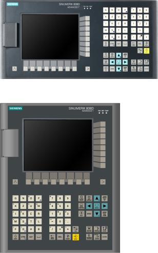
The SINUMERIK 808D ADVANCED PPU (Panel Processing Unit) is available in the following variants:
●PPU161.2
Horizontal panel layout, applicable for the SINUMERIK 808D ADVANCED T (turning) or SINUMERIK 808D ADVANCED M (milling) control system
●PPU160.2
Vertical panel layout, applicable for the SINUMERIK 808D ADVANCED T (turning) or SINUMERIK 808D ADVANCED M (milling) control system
PPU161.2 (horizontal panel layout)
PPU160.2 (vertical panel layout)
Programming and Operating Manual (Turning) |
7 |
6FC5398-5DP10-0BA1, 01/2014 |
1.1.2Control elements on the PPU
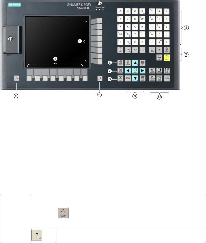
Elements on the PPU (Panel Processing Unit) front
The following illustration uses PPU161.2 as an example to show control elements available on the PPU:
|
Vertical and horizontal softkeys |
|
On-board wizard key |
||||
|
Calls specific menu functions |
|
Provides step-by-step guides on basic commissioning |
||||
|
|
|
|
|
|
and operation procedures |
|
|
Return key |
|
|
Help key |
|||
|
Returns to the next higher-level menu |
|
Calls help information |
||||
|
Menu extension key |
|
|
Cursor keys * |
|||
|
Opens the next lower-level menu or navigate between |
|
|
|
|||
|
the menus of the same level |
|
|
|
|
||
|
Alphabetic and numeric keys * |
|
Operating area keys * |
||||
|
Control keys * |
|
|
USB interface * |
|||
|
Alarm cancellation key |
|
|
Status LEDs * |
|||
|
Cancels alarms and messages that are marked with |
|
|
|
|||
|
this symbol |
|
|
|
|
||
* For more information, refer to the table below. |
|
|
|
||||
Further information |
|
|
|
|
|||
|
|
|
|
|
|||
Alphabetic and |
|
To enter the upper character on an alphabetic/numeric key, keep the following key |
|||||
numeric keys |
|
pressed: |
|
|
|
||
|
|
|
|
|
|
|
|
The icons on the following keys are available only with PPU161.2 and PPU160.2.
The icon on the key is a hint that you can press both <CTRL> and this key as shortcuts for capturing screens.
8 |
Programming and Operating Manual (Turning) |
6FC5398-5DP10-0BA1, 01/2014 |

|
|
The icon on the key is a hint that you can press both <CTRL> and this key as shortcuts |
|
|
for saving start-up archives. |
|
|
|
|
|
The icon on the key is a hint that you can press both <CTRL> and this key as shortcuts |
|
|
for displaying pre-defined slides on the screen. |
|
|
|
|
|
The icon on the key is a hint that you can press this key to call the calculator function. |
|
|
|
Cursor keys |
|
● Toggles between entries in the input field |
|
|
● Enters the "Set-up menu" dialog at NC start-up |
|
|
|
|
|
Icons on both keys are available only with PPU161.2 and PPU160.2. The icon on the |
|
|
key is a hint that you can press both <CTRL> and the key to adjust the screen backlight |
|
|
brightness. |
|
|
|
|
|
|
Control keys |
|
The icon on the key is available only with PPU161.2 and PPU160.2. The icon is a hint |
|
|
that this key can be used together with another key to function as a key combination. |
|
|
|
Operating area |
|
To open the system data management operating area, press the following key |
keys |
|
combination: |
|
|
+ |
|
|
Enables user-defined extension applications, for example, generation of user dialogs |
|
|
with the EasyXLanguage function. |
|
|
For more information about this function, refer to SINUMERIK 808D ADVANCED |
|
|
Function Manual. |
Status LEDs |
|
LED "POK" |
|
|
Lights up green: The power supply for the CNC is switched on. |
|
|
LED "RDY" |
|
|
Lights up green: The CNC is ready and the PLC is in running mode. |
|
|
Lights up orange: |
|
|
● On: The PLC is in stop mode. |
|
|
● Flashing: The PLC is in power-up mode. |
|
|
Lights up red: The CNC is in stop mode. |
|
|
LED "TEMP" |
|
|
Unlit: The CNC temperature is within the specified range. |
|
|
Lights up orange: The CNC temperature is out of range. |
USB interface |
|
Connects to a USB device, for example: |
|
|
● An external USB memory sticker, to transfer data between the USB sticker and the |
|
|
CNC |
|
|
● An external USB keyboard which functions as an external NC keyboard |
Programming and Operating Manual (Turning) |
9 |
6FC5398-5DP10-0BA1, 01/2014 |
1.2Machine control panels
1.2.1Overview
Elements on the MCP (Machine Control Panel) front
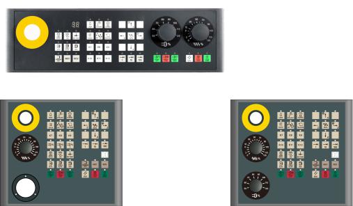
The MCP for the SINUMERIK 808D ADVANCED PPU is available in the following variants:
●Horizontal MCP variant
●Vertical MCP variant with a reserved slot for the handwheel
●Vertical MCP variant with an override switch for the spindle
Horizontal MCP
Vertical MCP with reserved handwheel slot |
Vertical MCP with spindle override switch |
10 |
Programming and Operating Manual (Turning) |
6FC5398-5DP10-0BA1, 01/2014 |
1.2.2Control elements on the MCP
Elements on the MCP (Machine Control Panel) front
The following illustration uses a horizontal MCP as an example to show control elements available on the MCP:
|
Reserved hole for emergency stop button |
|
|
Axis traversing keys |
|
|
Handwheel key |
|
|
Spindle override switch |
|
|
Controls the axis movement with external handwheels |
|
(unavailable for the vertical MCP with reserved |
||
|
|
|
|
|
handwheel slot) |
|
Tool number display |
|
|
Spindle state keys |
|
|
Displays the current tool number |
|
|
|
|
|
Operating mode keys |
|
|
Feedrate override switch |
|
|
|
|
|
|
Traverses the selected axis at the specified feedrate |
|
|
|
|
|
override |
|
Program control keys |
|
|
Keys for program start, stop, and reset |
|
|
User-defined keys * |
|
|
|
|
* For more information, refer to the table below. |
|
|
|
||
Further information |
|
|
|
||
|
|
|
|||
User-defined keys |
|
Pressing this in any operating mode switches on/off the lamp. |
|||
|
|
|
LED lit: The lamp is switched on. |
||
|
|
|
LED unlit: The lamp is switched off. |
||
|
|
|
|
||
|
|
|
Pressing this key in any operating mode switches on/off the coolant |
||
|
|
|
supply. |
|
|
|
|
|
LED lit: The coolant supply is switched on. |
||
|
|
|
LED unlit: The coolant supply is switched off. |
||
|
|
|
Pressing this key starts sequential tool changes (active only in "JOG" |
||
|
|
|
mode). |
|
|
|
|
|
LED lit: The machine starts sequential tool changes |
||
|
|
|
LED unlit: The machine stops sequential tool changes |
||
|
|
|
Pressing this key in any operating mode activates the chuck to |
||
|
|
|
clamp/unclamp the workpiece. |
||
|
|
|
LED lit: Activates the chuck to clamp the workpiece |
||
|
|
|
LED unlit: Activates the chuck to unclamp the workpiece |
||
Programming and Operating Manual (Turning) |
|
|
11 |
||
6FC5398-5DP10-0BA1, 01/2014 |
|
|
|||
Pressing this key only when the spindle stops operation.
LED lit: Activates the external chuck to clamp the workpiece inwards
LED unlit: Activates the internal chuck to clamp the workpiece outwards
Pressing this key in any operating mode advances/retracts the tailstock.
LED lit: Advances the tailstock towards the workpiece until it firmly engages with the end of the workpiece
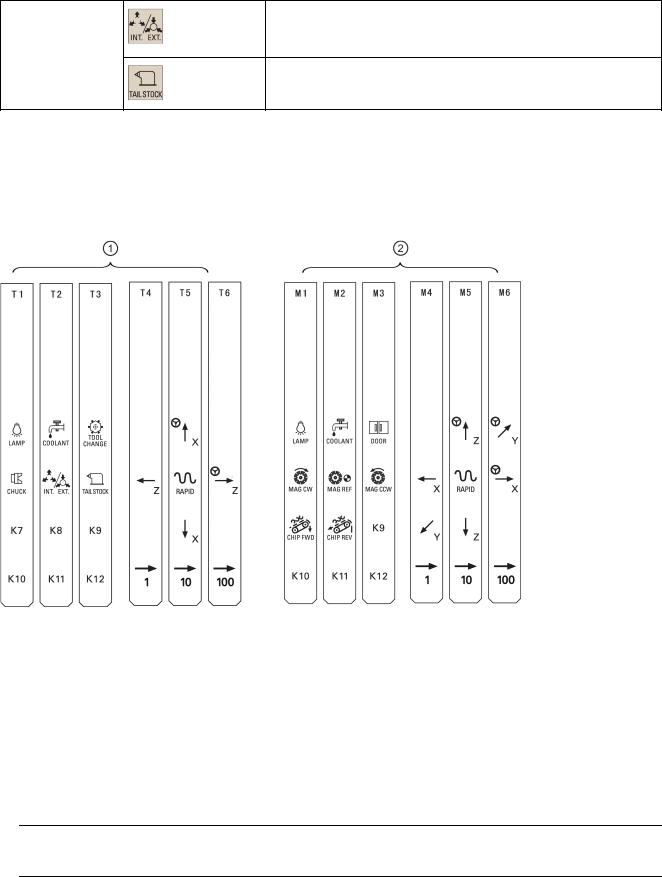
Pre-defined insertion strips
The MCP (machine control panel) package includes two sets (six pieces each) of pre-defined insertion strips. One set is for the turning variant of the control system and is pre-inserted on the back of the MCP. The other set is for the milling variant of the control system.
If your control system is of the SINUMERIK 808D ADVANCED milling variant, replace the pre-inserted strips with the millingspecific insertion strips.
Customized insertion strips
The MCP package also includes an A4-sized blank plastic sheet with detachable strips. You can customize insertion strips if the pre-defined strips can not meet your needs.
In the \examples\MCP folder of the Toolbox DVD for the SINUMERIK 808D ADVANCED, there is a symbol library file and an insertion strip template file. To make customized insertion strips, follow the steps below:
1.Copy the desired symbols from the symbol library file to the desired locations in the insertion strip template.
2.Print the template to the A4-sized blank plastic sheet.
3.Detach the insertion strips from the blank plastic sheet.
4.Pull out the pre-inserted strips from the MCP.
5.Insert the customized strips on the back of the MCP.
Note
This manual assumes an 808D standard machine control panel (MCP). Should you use a different MCP, the operation may be other than described herein.
12 |
Programming and Operating Manual (Turning) |
6FC5398-5DP10-0BA1, 01/2014 |
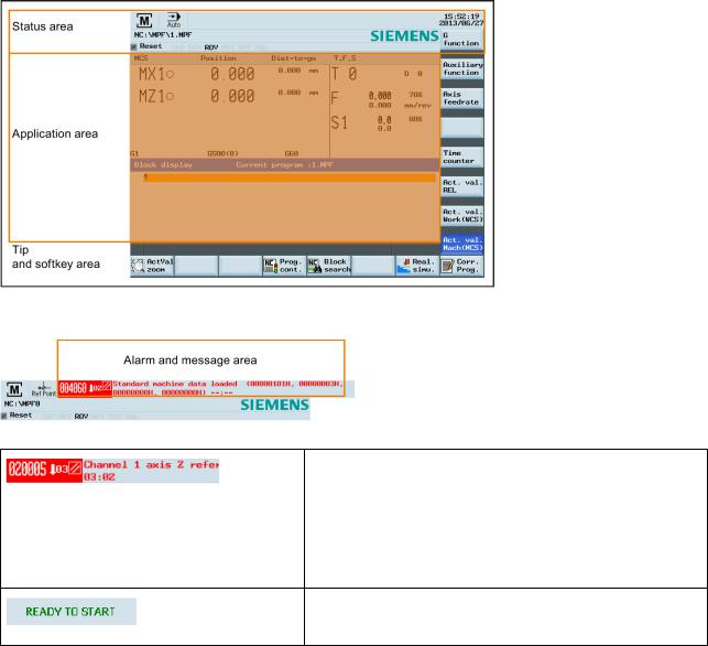
1.3Screen layout
Alarms and messages
Displays active alarms with alarm text
The alarm number is displayed in white lettering on a red background. The associated alarm text is shown in red lettering. An arrow indicates that several alarms are active. The number to the right of the arrow indicates the total number of active alarms. When more than one alarm is active, the display scrolls through the alarms in sequence. An acknowledgement symbol indicates the alarm cancel criterion.
Displays messages from NC programs
Messages from NC programs do not have numbers and appear in green lettering.
Programming and Operating Manual (Turning) |
13 |
6FC5398-5DP10-0BA1, 01/2014 |

1.4Protection levels
Overview
The SINUMERIK 808D ADVANCED provides a concept of protection levels for enabling data areas. Different protection levels control different access rights.
The control system delivered by SIEMENS is set by default to the lowest protection level 7 (without password). If the password is no longer known, the control system must be reinitialized with the default machine/drive data. All passwords are then reset to default passwords for this software release.
Note
Before you boot the control system with default machine/drive data, make sure that you have backed up your machine/drive data; otherwise, all data are lost after rebooting with default machine/drive data.
Protection level |
Locked by |
Area |
0 |
Siemens password |
Siemens, reserved |
1 |
Manufacturer password |
Machine manufacturers |
2 |
Reserved |
|
3-6 |
End user password |
End users |
|
(Default password: "CUSTOMER") |
|
7 |
No password |
End users |
Protection level 1
Protection level 1 requires a manufacturer password. With this password entry, you can perform the following operations: ● Entering or changing part of the machine data and drive data
●Conducting NC and drive commissioning Protection level 3-6
Protection level 3-6 requires an end user password. With this password entry, you can perform the following operations:
●Entering or changing part of the machine data and drive data
●Editing programs
●Setting offset values
●Measuring tools
Protection level 7
Protection level 7 is set automatically if no password is set and no protection level interface signal is set. The protection level 7 can be set from the PLC user program by setting the bits in the user interface.
In the menus listed below the input and modification of data depends on the set protection level:
●Tool offsets
●Work offsets
●Setting data
●RS232 settings
●Program creation/program correction
The number of machine data and drive data which can be read or modified depends on the protection level. You can set the protection level for these function areas with the display machine data (USER_CLASS...).
Setting password
You can set the desired password through the following operating area:
+ |
→ |
14 |
Programming and Operating Manual (Turning) |
6FC5398-5DP10-0BA1, 01/2014 |

1.5Setting user interface language
Operating sequence
1. Select the desired operating area.
+
2.Press this softkey to open the user interface language selection window.
3. Use the cursor keys to select the desired language.
4.Press this softkey to confirm your selection. Note:
The HMI (Human Machine Interface) is automatically restarted when a new language is selected.
2 Turning on, reference point approach
Note
When turning on the CNC and the machine, also observe the machine tool manufacturer's documentation, since turning-on and reference point approach are machine-dependent functions.
Operating sequence
1.Switch on the power supply for the control system and the machine.
2.Release all emergency stop buttons on the machine.
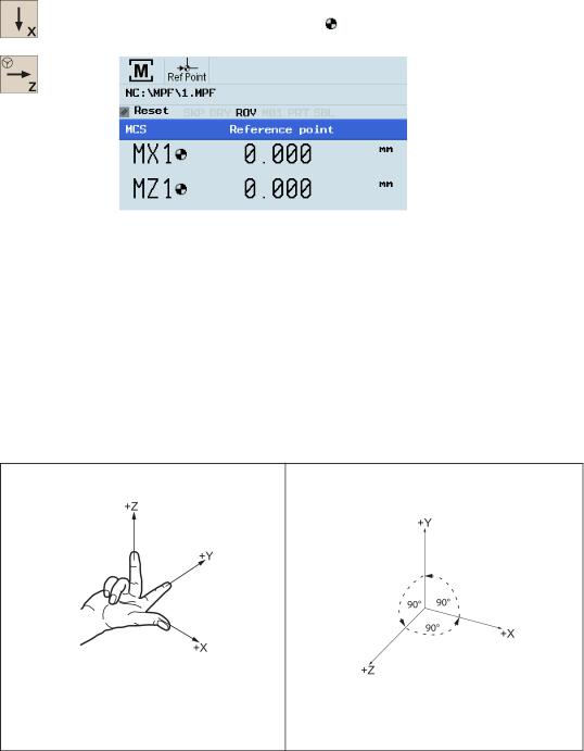
By default, the control system is in the "REF POINT" window after booting.
The symbol shown next to the axis identifier indicates that the axis is not yet referenced. If an axis is not referenced, the symbol is always visible in the current (machining) operating area.
Programming and Operating Manual (Turning) |
15 |
6FC5398-5DP10-0BA1, 01/2014 |
3.Press the corresponding axis traversing keys on the MCP to traverse each axis to the reference point.
If the axis is referenced, a symbol ( ) appears next to the axis identifier and is visible only in the "REF POINT" window.
Note that axis traversing directions and axis key functions are defined by the machine manufacturer.
3 Setting-up
3.1Coordinate systems
As a rule, a coordinate system is formed from three mutually perpendicular coordinate axes. The positive directions of the coordinate axes are defined using the so-called "3-finger rule" of the right hand. The coordinate system is related to the workpiece and programming takes place independently of whether the tool or the workpiece is being traversed. When programming, it is always assumed that the tool traverses relative to the coordinate system of the workpiece, which is intended to be stationary.
The figure below illustrates how to determine the axis directions.
Machine coordinate system (MCS)
The orientation of the coordinate system relative to the machine depends on the machine type. It can be rotated in different positions.
The directions of the axes follow the "3-finger rule" of the right hand. Seen from the front of the machine, the middle finger of the right hand points in the opposite direction to the infeed of the spindle.
16 |
Programming and Operating Manual (Turning) |
6FC5398-5DP10-0BA1, 01/2014 |
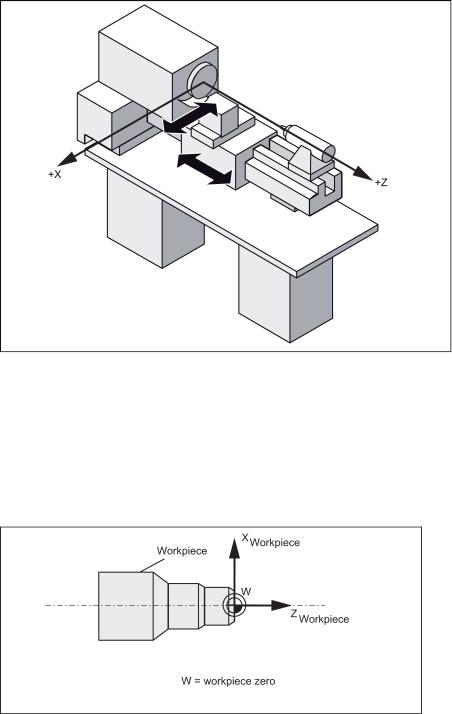
The figure below shows an example of the machine coordinate system of a turning machine.
The origin of this coordinate system is the machine zero.
This point is only a reference point which is defined by the machine manufacturer. It does not have to be approachable. The traversing range of the machine axes can be in the negative range.
Workpiece coordinate system (WCS)
To describe the geometry of a workpiece in the workpiece program, a right-handed, right-angled coordinate system is also used.
The workpiece zero can be freely selected by the programmer in the Z axis. In the X axis, it lies in the turning center. The figure below shows an example of the workpiece coordinate system.
Relative coordinate system (REL)
In addition to the machine and workpiece coordinate systems, the control system provides a relative coordinate system. This coordinate system is used to set reference points that can be freely selected and have no influence on the active workpiece coordinate system. All axis movements are displayed relative to these reference points.
Programming and Operating Manual (Turning) |
17 |
6FC5398-5DP10-0BA1, 01/2014 |
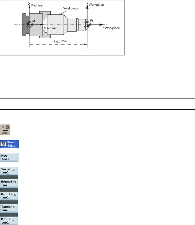
Clamping the workpiece
For machining, the workpiece is clamped on the machine. The workpiece must be aligned such that the axes of the workpiece coordinate system run in parallel with those of the machine. Any resulting offset of the machine zero with reference to the workpiece zero is determined along the Z axis and entered in a data area intended for the settable work offset. In the NC program, this offset is activated during program execution, for example, using a programmed G54 command.
The figure below shows an example of the workpiece clamped on the machine.
Current workpiece coordinate system
The programmed work offset TRANS (Page 53) can be used to generate an offset with reference to the workpiece coordinate system, resulting in the current workpiece coordinate system.
3.2Setting up tools
3.2.1Creating a new tool
Note
The control system supports a maximum of 64 tools or 128 cutting edges.
Operating sequence
1. Select the desired operating area.
2.Open the tool list window.
3.Open the lower-level menu for tool type selection.
4.Select a desired tool type with the corresponding softkey.
18 |
Programming and Operating Manual (Turning) |
6FC5398-5DP10-0BA1, 01/2014 |
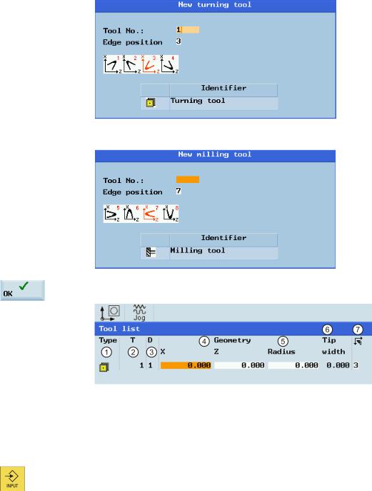
5.Enter the tool number (value range: 1 to 31999; preferentially enter a value less than 100) and select the corresponding tool edge position code according to the actual tool point direction in the following windows:
●Available edge positions for turning tool and grooving tool: 1, 2, 3 and 4 (taking new turning tool as an example)
●Available edge positions for drilling tool, tapping tool and milling tool: 5, 6, 7 and 8 (taking new milling tool as an example)
6.Use this softkey to confirm your settings. The window below shows the information of the new tool created.
Tool type
Tool number
Cutting edge number
Tool length in the X and Z axes
Tool radius
Tip width of the cutting edge, which is only active for the grooving tool
Cutting edge direction
7. Enter the tool radius data or tool tip width as desired and confirm your settings.
Programming and Operating Manual (Turning) |
19 |
6FC5398-5DP10-0BA1, 01/2014 |
3.2.2Activating the tool
Operating sequence
1. Select the desired operating area.
2. Switch to "JOG" mode.
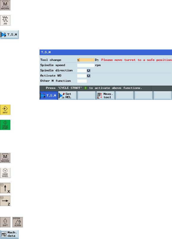
3.Open the "T, S, M" window.
4.Enter the desired tool number (for example, 1) in the "T, S, M" window.
5. Use this key or move the cursor to confirm your entries.
6. Press this key on the MCP to activate the tool.
3.2.3Assigning the handwheel
Method 1: Assigning through the MCP
1. Select the desired operating area.
2. Press this key on the MCP to control the axis movement with external handwheels.
3. Press the desired axis traversing key with the handwheel icon. The handwheel is assigned.
Method 2: Assigning through the PPU
1.Select the desired operating area.
+
2.Open the machine data window.
20 |
Programming and Operating Manual (Turning) |
6FC5398-5DP10-0BA1, 01/2014 |
3. Press this softkey to open the basic machine data list.
4.Use the cursor keys or the following softkey to search for the general machine data "14512
USER_DATA_HEX[16]".
5.Select "Bit7" by using the following key and cursor keys:
Press the following softkey to confirm your input.
6.Press this vertical softkey to activate the value change. Note that the control system restarts to accept the new value.
7.After the control system has booted, select the desired operating area.
8.Press this key on the MCP.
9.Press this vertical softkey to open the handwheel assignment window.
10.Select the desired handwheel number with the cursor left/right key.
11.Press the relevant axis softkey for handwheel assignment or deselection.
The symbol " " that appears in the window indicates a handwheel has been assigned to the specific axis.
12.Select the required override increment. The selected axis can now be moved with the handwheel.
The override increment is 0.001 mm.
The override increment is 0.010 mm.
The override increment is 0.100 mm.
Programming and Operating Manual (Turning) |
21 |
6FC5398-5DP10-0BA1, 01/2014 |
3.2.4Activating the spindle
Operating sequence
1. Select the desired operating area.
2. Switch to "JOG" mode.
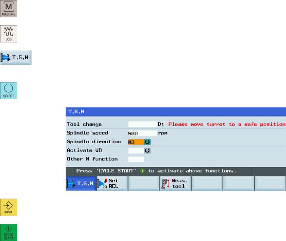
3.Open the "T, S, M" window.
4.Enter the desired value for the spindle speed in the "T, S, M" window.
5. Press this key to select the spindle direction.
6. Use this key or move the cursor to confirm your entries.
7. Press this key on the MCP to activate the spindle.
3.2.5Measuring the tool (manually)
Overview
The geometries of the machining tool must be taken into consideration when you execute a part program. These are stored as tool offset data in the tool list. Each time the tool is called, the control considers the tool offset data.
You can determine the tool offset data, including the length, radius and diameter by either measuring the tool or entering the values in the tool list (see Section "Creating a new tool (Page 18)" for more information).
As per the actual position of the point F (the machine coordinate) and the reference point, the control system can calculate the offset value assigned to the lengths for the X and Z axes.
22 |
Programming and Operating Manual (Turning) |
6FC5398-5DP10-0BA1, 01/2014 |

Figure 3-1 Determining the length offsets using the example of a turning tool
Figure 3-2 Determining the length offsets using the example of a drill: Length 1/Z axis
Figure 3-3 |
Determining the length offsets using the example of a milling tool |
|
Programming and Operating Manual (Turning) |
23 |
|
6FC5398-5DP10-0BA1, 01/2014 |
||
Operating sequence
Measuring the tool in the X direction
1. Select the desired operating area.
2. Switch to "JOG" mode.
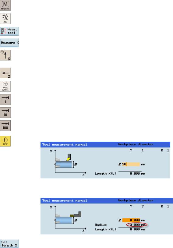
3. Open the manual tool measurement window.
4. Press this vertical softkey to measure the tool in the X direction. 5. Move the tool to approach the workpiece in the X direction.
...
6. Switch to handwheel control mode.
7.Select a suitable override feedrate, and then use the handwheel to move the tool to scratch the required workpiece edge (or the edge of the setting block, if it is used).
8. Enter the workpiece diameter in the "Ø" field (for example, 50).
Note:
For a milling tool with edge position 5 or 7, the radius of the tool itself is displayed in the following window:
9.Save the length value in the X axis. The tool diameter, radius, and cutting edge position are all taken in to account.
24 |
Programming and Operating Manual (Turning) |
6FC5398-5DP10-0BA1, 01/2014 |
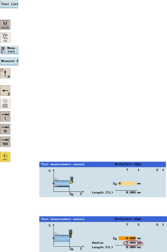
10.Press this softkey and you can see that the compensation data values have been automatically added to the tool data.
Measuring the tool in the Z direction
1. Select the desired operating area.
2. Switch to "JOG" mode.
3. Open the manual tool measurement window.
4. Press this vertical softkey to measure the tool in the Z direction. 5. Move the tool to approach the workpiece in the Z direction.
...
6. Switch to handwheel control mode.
7.Select a suitable override feedrate, and then use the handwheel to move the tool to scratch the required workpiece edge (or the edge of the setting block, if it is used).
8.Enter the distance between the tool tip and the workpiece edge in the "Z0" field, for example, "0". (This value is the thickness of a setting block if it is used.)
Note:
For a milling tool with edge position 6 or 8, the radius of the tool itself is displayed in the following window:
Programming and Operating Manual (Turning) |
25 |
6FC5398-5DP10-0BA1, 01/2014 |
9. Save the length value in the Z axis.
10.Press this softkey and you can see that the compensation data values have been automatically added to the tool data.
Repeat the above operations for other tools and make sure you measure all the tools before machining, which also eases the tool changing process.
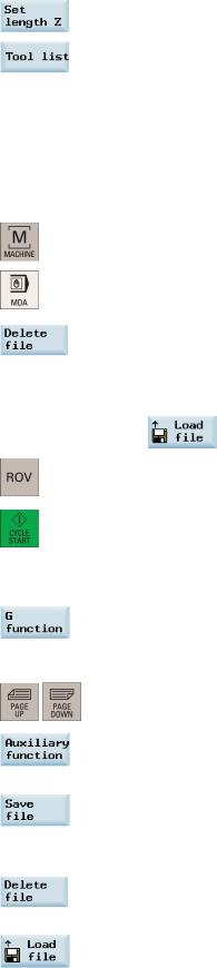
3.2.6Verifying the tool offset result in "MDA" mode
In order to ensure the machine safety and correctness, you must test the results of the tool offset appropriately.
Operating sequence
1. Select the desired operating area.
2. Switch to "MDA" mode.
3. Press this softkey on the PPU.
4.Enter the test program, for example: G500 T1 D1 G00 X0 Z5.
You can alternatively load an existing part program from a system directory using the following softkey if desired:
5.Press this key to ensure the "ROV" function is active (lit up).
Note:
The "ROV" function activates the feedrate override switch under the G00 function.
6.Press this key on the MCP.
Increase the feedrate override gradually to avoid accidents caused by an axis moving too fast and observe whether the axis moves to the set position.
Further softkey functions in "MDA" mode
This window displays important G functions whereby each G function is assigned to a group and has a fixed position in the window. To close the window, press this softkey once again.
To display additional G functions, use the following keys:
This window displays the auxiliary and M functions currently active. To close the window, press this softkey once again.
This softkey opens the file saving window where you can specify a name and a storage medium for the program displayed in the MDA window. To save your program, either enter a new program name in the input field or select an existing program for overwriting.
Note: If you do not save with this softkey, the program edited in "MDA" mode is actually a temporary file. Pressing this softkey deletes all the blocks displayed in the MDA window.
This softkey opens a window where you can select an existing program file from a system directory to load into the MDA buffer.
For the explanation of other softkeys in this mode, refer to Section "Other settings in "JOG" mode (Page 211)".
26 |
Programming and Operating Manual (Turning) |
6FC5398-5DP10-0BA1, 01/2014 |

3.2.7Entering/modifying the tool wear data
Note
You must distinguish the direction of tool wear compensation clearly.
Operating sequence |
|
1. |
Select the desired operating area. |
2. |
Open the tool wear window. |
3. |
Use the cursor keys to select the required tools and their edges. |
4.Enter the tool length wear parameter of axis X and axis Z as well as the tool radius wear parameter.
Positive value: The tool moves away from the workpiece. Negative value: The tool moves closer to the workpiece.
5. Press this key or move the cursor to activate the compensation.
Programming and Operating Manual (Turning) |
27 |
6FC5398-5DP10-0BA1, 01/2014 |
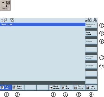
3.3Operating area overview
When working with the CNC, you need to set up the machine and the tools, etc. as follows:
●Create the tools and cutting edges.
●Enter/modify the tool and work offsets.
●Enter the setting data.
Softkey functions
Pressing this key on the PPU allows you to open the following window:
|
Displays and modifies the tool offsets |
|
Measures the tool manually |
|
Displays and modifies the tool wear data |
|
Creates a new tool |
|
|
|
For more information, see Section "Creating a new |
|
|
|
tool (Page 18)". |
|
Displays and modifies the work offsets |
|
Opens a lower-level menu for cutting edge settings |
|
|
|
For more information, see Section "Creating a new |
|
|
|
cutting edge (Page 204)". |
|
Displays and modifies the R variables |
|
Removes the currently selected tool from the tool list |
|
Configures and displays lists of setting data |
|
Searches for your desired tool with the tool number |
|
Displays the defined user data |
|
|
28 |
Programming and Operating Manual (Turning) |
6FC5398-5DP10-0BA1, 01/2014 |
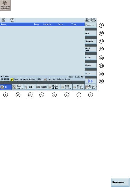
4 Part programming
The SINUMERIK 808D ADVANCED control system can store a maximum of 300 part programs which include those created by the control system for certain functions such as MM+, TSM, and so on.
Softkey functions
Pressing this key on the PPU allows you to open the following window:
|
Stores the NC programs for subsequent operations |
|
Executes the selected file. No editing is allowed in the |
|
|
|
execution process |
|
Manages and transfers the manufacturer cycles |
|
Creates new files or directories |
|
Reads in/out files via the USB drive and executes the |
|
Searches for files |
|
program from the external storage media |
|
|
|
Reads in/out files via the RS232 interface and |
|
Selects all files for the subsequent operations |
|
executes the program from an external PC/PG |
|
|
|
Reads in/out files via the Ethernet interface and |
|
Copies the selected file(s) to the clipboard |
|
executes the program from an external PC/PG |
|
|
|
Backs up manufacturer files |
|
Pastes the selected file(s) from the clipboard to the |
|
|
|
current directory |
|
Backs up user files |
|
Restores the deleted file(s) |
|
Shows the recently accessed files |
|
Opens the second-level softkeys, for example: |
|
|
|
|
Programming and Operating Manual (Turning) |
29 |
6FC5398-5DP10-0BA1, 01/2014 |
4.1Creating a part program
Operating sequence
To create a part program, follow these steps:
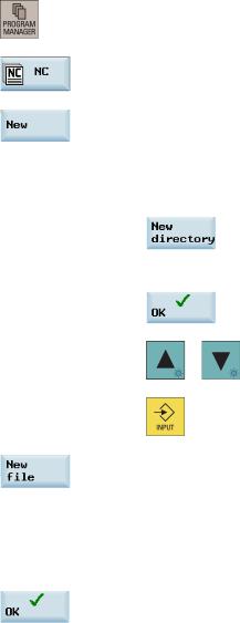
1. Select the desired operating area.
2.Enter the folder for the new program to be created.
3.If you desire to directly create a new program file, press this softkey and proceed to Step 4.
Note:
If you desire to create a new program directory first, press this softkey and proceed as follows before you go to Step 4:
Press this softkey to activate the window for creating a new directory.
Enter a desired name for the new directory.
Press this softkey to confirm your entry.
|
Select the new directory with the cursor keys. |
|
Press this key on the PPU to open the directory. |
4.Press this softkey to activate the window for creating a new program.
5.Enter the name of the new program. If you desire to create a main program, it is unnecessary to enter the file extension ".MPF". If you desire to create a subprogram, you must enter the file extension ".SPF". The character length of a program name is limited to 24 English characters or 12 Chinese characters. It is recommended that you do not use any special characters in the program name.
6.Press this softkey to confirm your entry. The part program editor window opens. Enter the blocks in the window, which are saved automatically.
30 |
Programming and Operating Manual (Turning) |
6FC5398-5DP10-0BA1, 01/2014 |
Loading...