


 Loading...
SINUMERIK 802S/C
Manual Machine
Operator’s Guide
Valid for |
|
Software |
Version |
SINUMERIK 802S/C |
3.1.0 or higher |
04/2005 Edition
Overview of Controls
Sequence of
Operations
Tool Data
Functions
Service Functions
Saving Data
Switching to the Standard Operator Interface
Shutting Down the
Controller
Menu Tree
Messages
1
2
3
4
5
6
7
8
9
10
SINUMERIK® Documentation
Printing history
Brief details of this edition and previous editions are listed below.
The status of each edition is indicated by the code in the "Remarks" column.
Status code in the "Remarks" column:
A .... |
New documentation. |
|
|
B .... Unrevised reprint with new order number |
|
||
C .... |
Revised edition with new status |
|
|
Edition |
Order No. |
Remarks |
|
04/2005 |
--- |
A |
|
Trademarks
SIMATIC®, SIMATIC HMI®, SIMATIC NET®, SIROTEC®, SINUMERIK® and SIMODRIVE® are registered trademarks of Siemens AG. Other names used in this publication may be trademarks, which, if used by third parties for their own means, may violate the rights of their owners.
Additional information is available in the Internet at: http://www.siemens.com/motioncontrol
This publication has been produced using WinWord V 8.0, Designer V 7.0 and the DocuTool AutWinDoc.
Other functions not described in this documentation may be executable in the control. This does not, however, represent an obligation to supply such functions with a new control or when servicing.
We have checked the contents of this manual for agreement with the hardware and software described. Nevertheless, differences might exist and we cannot, therefore, guarantee that they are completely identical. However, the data in this manual are reviewed regularly and any necessary corrections included in subsequent editions. Suggestions for improvement are welcome.
© Siemens AG, 2005. All rights reserved |
Technical data subject to change. |
|
|
Order No. --- |
Siemens Aktiengesellschaft |
Printed in Germany |
|
04/2005 |
Preface |
Preface
SINUMERIK documentation
The SINUMERIK documentation is organized in 3 parts:
•General documentation
•User documentation
•Manufacturer/Service documentation
Please contact your local Siemens office for more detailed information about other SINUMERIK 802D publications.
An overview of publications that is updated monthly is provided in a number of languages in the Internet at:
http://www.siemens.com/motioncontrol
Follow menu items "Support" Æ "Technical Documentation" Æ "Overview of Documents".
The Internet version of the DOConCD (DOConWEB) is available at:
http://www.automation.siemens.com/doconweb
Target readership
This Manual is intended for machine-tool users. This publication provides detailed information that the user requires for operating the SINUMERIK 810D and 840D controls.
Standard scope
This Operator’s Guide describes the functionality of the standard scope. Extensions or changes made by the machine tool manufacturer are documented by the machine tool manufacturer.
Other functions not described in this documentation may be executable in the control. This does not, however, represent an obligation to supply such functions with a new module or when servicing.
© Siemens AG, 2005. All rights reserved |
iii |
SINUMERIK 802S/C BA_MM (BA) – 04/2005 Edition |

Preface |
04/2005 |
Hotline
If you have any questions, please get in touch with our Hotline: A&D Technical Support
Phone.: +49 (0) 180 / 5050 - 222 Fax: +49 (0) 180 / 5050 - 223
E-mail: mailto:adsupport@siemens.com
Internet: http://www.siemens.com/automation/support-request
If you have any queries (suggestions, corrections) in relation to this documentation, please fax or e-mail us:
Fax: +49 (0) 9131 / 98 - 63315
E-mail: mailto:motioncontrol.docu@siemens.com
Fax form: See the reply form at the end of the document.
SINUMERIK Internet address
http://www.siemens.com/motioncontrol
Safety notes
This Manual contains information which you should carefully observe to ensure your own personal safety and the prevention of material damage. The notices are highlighted by a warning triangle The warnings are shown below in decreasing order of danger.
!Danger
Indicates an imminently hazardous situation which, if not avoided, will result in death or serious injury or in substantial property damage.
!Warning
Indicates a potentially hazardous situation which, if not avoided, could result in death or serious injury or in substantial property damage.
!Caution
Used with the safety alert symbol indicates a potentially hazardous situation which, if not avoided, may result in minor or moderate injury or in property damage.
iv |
© Siemens AG, 2005. All rights reserved |
SINUMERIK 802S/C BA_MM (BA) – 04/2005 Edition |

04/2005 |
Preface |
Caution
Used without safety alert symbol indicates a potentially hazardous situation which, if not avoided, may result in property damage.
Notice
Used without the safety alert symbol indicates a potential situation which, if not avoided, may result in an undesirable result or state.
If several hazards of different degrees occur, the hazard with the highest degree must always be given preference. If a warning note with a warning triangle warns of personal injury, the same warning note can also contain a warning of material damage.
Qualified personnel
Start-up and operation of the device/equipment/system in question must only be performed using this documentation. The device/system must only be commissioned and operated by qualified personnel. Qualified personnel as referred to in the safety guidelines in this documentation are those who are authorized to start up, earth and label units, systems and circuits in accordance with the relevant safety standards.
Proper use
Note the following:
!Warning
The device must only be used for the applications described in the Catalog and only in combination with the equipment, components and devices of other manufacturers as far as this is recommended or permitted by Siemens. It is assumed that this product be transported, stored and installed as intended and maintained and operated with care to ensure that the product functions correctly and properly.
© Siemens AG, 2005. All rights reserved |
v |
SINUMERIK 802S/C BA_MM (BA) – 04/2005 Edition |

Preface |
04/2005 |
Other information
!Important
This notice indicates important facts that must be taken into consideration.
Note
This symbol always appears in this documentation where further, explanatory information is provided.
Machine manufacturer
This pictorial symbol always appears in this document to indicate that the machine manufacturer can affect or modify the function described. Note the machine manufacturer’s instructions.
vi |
© Siemens AG, 2005. All rights reserved |
SINUMERIK 802S/C BA_MM (BA) – 04/2005 Edition |
04/2005 |
Contents |
Contents
1 Overview of Controls...................................................................... |
1-9 |
|
1.1 Operator panel.............................................................................. |
1-10 |
|
1.1.1 |
Key functions ............................................................................. |
1-10 |
1.1.2 |
Controls on the machine............................................................ |
1-11 |
2 Sequence of Operations ................................................................ |
2-13 |
||
2.1 |
Powering-up the control................................................................ |
2-14 |
|
2.2 |
Reference point approach ............................................................ |
2-14 |
|
2.2.1 |
Preparations for reference point approach ................................ |
2-14 |
|
2.2.2 |
Moving the axes ahead of the reference point .......................... |
2-15 |
|
2.2.3 |
Reference point approach ......................................................... |
2-16 |
|
2.3 Manual Machining......................................................................... |
2-17 |
||
2.3.1 |
Displays on the main "Manual Machining" screen:.................... |
2-18 |
|
2.3.2 |
Toggling the display................................................................... |
2-19 |
|
2.3.3 |
Machining with the handwheels................................................. |
2-20 |
|
2.3.4 |
Handwheel valuation setting...................................................... |
2-20 |
|
2.3.5 |
Machining with the 4-way switch/axis direction keys................. |
2-20 |
|
2.3.6 |
Spindle advance/reverse ........................................................... |
2-21 |
|
2.3.7 |
Jog spindle................................................................................. |
2-21 |
|
2.3.8 |
Tool change ............................................................................... |
2-22 |
|
2.3.9 |
Machining technology data ........................................................ |
2-23 |
|
2.3.10 |
Changing the spindle/feedrate value ....................................... |
2-24 |
|
2.3.11 |
Entering machining technology data: ...................................... |
2-25 |
|
2.3.12 |
Spindle positioning................................................................... |
2-27 |
|
3 Tool Data.......................................................................................... |
3-29 |
|
3.1 |
Tool list.......................................................................................... |
3-30 |
3.2 |
Tool calibration.............................................................................. |
3-31 |
3.3 |
Geometry tool data ....................................................................... |
3-32 |
3.4 |
Entering tool technology data ....................................................... |
3-33 |
3.5 |
Deleting tool technology data ....................................................... |
3-35 |
4 Functions......................................................................................... |
4-37 |
|
4.1 Limit stops..................................................................................... |
4-38 |
|
4.1.1 |
Setting limit stops....................................................................... |
4-38 |
4.1.2 |
Activating/disabling limit stops................................................... |
4-40 |
4.1.3 |
Turning against mechanical stoppage....................................... |
4-41 |
© Siemens AG, 2005. All rights reserved |
vii |
Sinumerik 802S/C BA_MM (BA) – 04/2005 Edition |
Contents |
04/2005 |
4.2 |
Taper turning................................................................................. |
4-42 |
|
4.3 |
Radius turning............................................................................... |
4-44 |
|
4.4 |
Drilling - centered.......................................................................... |
4-46 |
|
4.5 |
Tapping ......................................................................................... |
4-49 |
|
4.6 |
Groove cycles/parting ................................................................... |
4-53 |
|
4.6.1 |
Groove cycle - single ................................................................. |
4-53 |
|
4.6.2 |
Groove cycle - multiple .............................................................. |
4-57 |
|
4.6.3 |
Parting........................................................................................ |
4-59 |
|
4.6.4 |
Multiple parting .......................................................................... |
4-60 |
|
4.7 |
|
Thread cutting.............................................................................. |
4-61 |
4.7.1 |
Longitudinal thread cutting......................................................... |
4-61 |
|
4.7.2 |
Thread recutting......................................................................... |
4-65 |
|
4.7.3 |
Thread shaving after thread cutting........................................... |
4-67 |
|
4.8 |
Cutting cycles................................................................................ |
4-68 |
|
4.8.1 |
Cutting cycle A........................................................................... |
4-69 |
|
4.8.2 |
Cutting cycle B........................................................................... |
4-73 |
|
4.8.3 |
Cutting cycle C........................................................................... |
4-77 |
|
4.9 |
Setting the workpiece zero point................................................... |
4-80 |
|
5 Service Functions........................................................................... |
5-83 |
||
6 Saving Data ..................................................................................... |
6-85 |
||
7 Switching to the Standard Operator Interface ............................. |
7-87 |
||
7.1 |
General ......................................................................................... |
7-88 |
|
7.2 |
"Reference Point Level" starting point .......................................... |
7-88 |
|
7.3 |
"Manual Machining" starting point ................................................ |
7-89 |
|
7.3.1 |
Switching back to the "Manual Machine" operator interface ..... |
7-91 |
|
8 Shutting Down the Controller........................................................ |
8-93 |
||
9 Menu Tree ........................................................................................ |
9-95 |
||
10 Messages....................................................................................... |
10-99 |
||
viii |
© Siemens AG, 2005. All rights reserved |
Sinumerik 802S/C BA_MM (BA) – 04/2005 Edition |
04/2005 |
1 Overview of Controls |
|
|
1.1 Operator panel |
|
1
1 Overview of Controls
1.1 Operator panel.............................................................................. |
1-10 |
|
1.1.1 |
Key functions ............................................................................. |
1-10 |
1.1.2 |
Controls on the machine............................................................ |
1-11 |
© Siemens AG, 2005. All rights reserved |
1-9 |
SINUMERIK 802S/C BA_MM (BA) – 04/2005 Edition |

1 Overview of Controls |
04/2005 |
1.1 Operator panel |
|
1.1 Operator panel
Fig. 1-1: Operator panel
1.1.1 Key functions
Move cursor in the direction of the arrow
Enter key (accept entry values)
Delete character (from right to left)
Acknowledge alarm
Extended menu (only if the corresponding symbol appears on the screen)
Back key
(only if the corresponding symbol appears on the screen)
Monitor key, used exclusively for switching to the standard operator interface (Sinumerik 802S/C base line).
1-10 |
© Siemens AG, 2005. All rights reserved |
SINUMERIK 802S/C BA_MM (BA) – 04/2005 Edition |
04/2005 |
1 Overview of Controls |
|
|
1.1 Operator panel |
|
Key not used for machine operation
Toggle key for handwheel valuation
JOG key for selecting “JOG” mode
1.1.2 Controls on the machine
(if provided by the machine manufacturer)
•NC start key
•NC stop key
•4-way switch or axis direction keys (X+/X-/Z+/Z-) for axis movement
•Rapid traverse override switch or key for axis movement
•Spindle joystick or spindle direction keys for spindle control (clockwise or counterclockwise rotation)
•Jog spindle key
•Handwheel for X and Z axis
•Emergency Stop button
© Siemens AG, 2005. All rights reserved |
1-11 |
SINUMERIK 802S/C BA_MM (BA) – 04/2005 Edition |
1 Overview of Controls |
04/2005 |
1.1 Operator panel |
|
1-12 |
© Siemens AG, 2005. All rights reserved |
SINUMERIK 802S/C BA_MM (BA) – 04/2005 Edition |
04/2005 |
2 Sequence of Operations |
|
|
2.1 Powering-up the control |
|
2
2 Sequence of Operations
2.1 |
Powering-up the control................................................................ |
2-14 |
|
2.2 |
Reference point approach ............................................................ |
2-14 |
|
2.2.1 |
Preparations for reference point approach ................................ |
2-14 |
|
2.2.2 |
Moving the axes ahead of the reference point .......................... |
2-15 |
|
2.2.3 |
Reference point approach ......................................................... |
2-16 |
|
2.3 Manual Machining......................................................................... |
2-17 |
||
2.3.1 |
Displays on the main "Manual Machining" screen:.................... |
2-18 |
|
2.3.2 |
Toggling the display................................................................... |
2-19 |
|
2.3.3 |
Machining with the handwheels................................................. |
2-20 |
|
2.3.4 |
Handwheel valuation setting...................................................... |
2-20 |
|
2.3.5 |
Machining with the 4-way switch/axis direction keys................. |
2-20 |
|
2.3.6 |
Spindle advance/reverse ........................................................... |
2-21 |
|
2.3.7 |
Jog spindle................................................................................. |
2-21 |
|
2.3.8 |
Tool change ............................................................................... |
2-22 |
|
2.3.9 |
Machining technology data ........................................................ |
2-23 |
|
2.3.10 |
Changing the spindle/feedrate value ....................................... |
2-24 |
|
2.3.11 |
Entering machining technology data: ...................................... |
2-25 |
|
2.3.12 |
Spindle positioning................................................................... |
2-27 |
|
© Siemens AG, 2005. All rights reserved |
2-13 |
SINUMERIK 802S/C BA_MM (BA) – 04/2005 Edition |
2 Sequence of Operations |
04/2005 |
2.1 Powering-up the control |
|
2.1 Powering-up the control
Unless the machine manufacturer has set it up differently, the controller powers up automatically when the power supply is switched on. Internal test routines are performed during the power-up process. Once they have been successfully completed, the controller opens and displays the Reference Point screen form.
2.2 Reference point approach
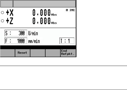
Once the controller has powered up, the Reference Point screen form appears:
Fig. 2-1: Reference point approach
!Note
Before starting the reference point approach, be sure to move the machine slide to a position from which the reference point can be approached in a positive axis direction.
2.2.1Preparations for reference point approach
Before you can approach the reference points for the two axes, the following conditions must be met:
Prerequisite
•There must be no NC alarms pending!
→Clear any that are pending by pressing the "Reset" function key.
•All machine axes must be in a position from which the reference point can be reached in a positive traversing direction.
→In manual mode, use the handwheels to move the axes to the appropriate position ahead of the reference point.
2-14 |
© Siemens AG, 2005. All rights reserved |
SINUMERIK 802S/C BA_MM (BA) – 04/2005 Edition |
04/2005 |
2 Sequence of Operations |
|
2.2 |
Reference point approach |
|
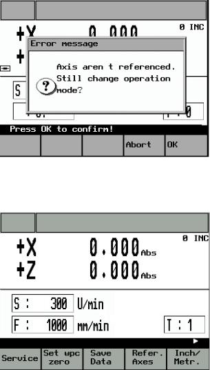
2.2.2Moving the axes ahead of the reference point
•Exit the Reference Point screen form by pressing the "End Refpkt" function key.
The following prompt appears:
Fig. 2-2: Exiting the Reference Point Approach screen
•Press "OK" to acknowledge the message and return to the main service functions menu.
Fig. 2-3: Main Service Functions screen
•Press the “JOG” key once (otherwise, it will not be possible to switch to handwheel valuation).
•Then use the toggle key to set the handwheel valuation. The current setting will appear on the top-right of the screen (e.g., 100 INC).
•Then use the handwheel to move the axes to a position from which they can approach the reference point in a positive direction.
© Siemens AG, 2005. All rights reserved |
2-15 |
SINUMERIK 802S/C BA_MM (BA) – 04/2005 Edition |

2 Sequence of Operations |
04/2005 |
2.2 Reference point approach |
|
Caution
In this operating mode the axes can only be approached using the handwheel. Use of the 4-way switch or axis direction keys to move the axes is blocked. In addition, the spindle cannot be started in this mode.
•Press the “Refer. Axes” function key to switch back to “Reference point approach” mode.
2.2.3Reference point approach
Displays
Axis has not yet been referenced
Axis has already reached the reference point (is referenced)
Once all the conditions have been met (→ Preparations for reference point approach), reference point approach can be started for each axis as follows:
•Using the 4-way switch or axis direction key, start the X axis in the positive direction (X+). The reference point for the X axis is then approached automatically.
•At the end of this process the axis stops automatically and the symbol is displayed in front of the axis name.
•Once the X axis has reached its reference point, the same process can be repeated for the Z axis (Z+).
!Note
The axes must be referenced in this sequence, i.e. the X axis first, followed by the Z axis. Any other sequence will not be accepted by the controller.
Caution
If the machine manufacturer has not fitted an axis limit switch, there is a risk of a mechanical collision if the axis is on the wrong side of the reference point cam before the start of the reference point approach.
→ Preparations for reference point approach.
•Press the "End Refpkt." function key once both axes have been referenced to return to the main "Manual Machining" screen.
2-16 |
© Siemens AG, 2005. All rights reserved |
SINUMERIK 802S/C BA_MM (BA) – 04/2005 Edition |
04/2005 |
2 Sequence of Operations |
|
|
2.3 Manual Machining |
|
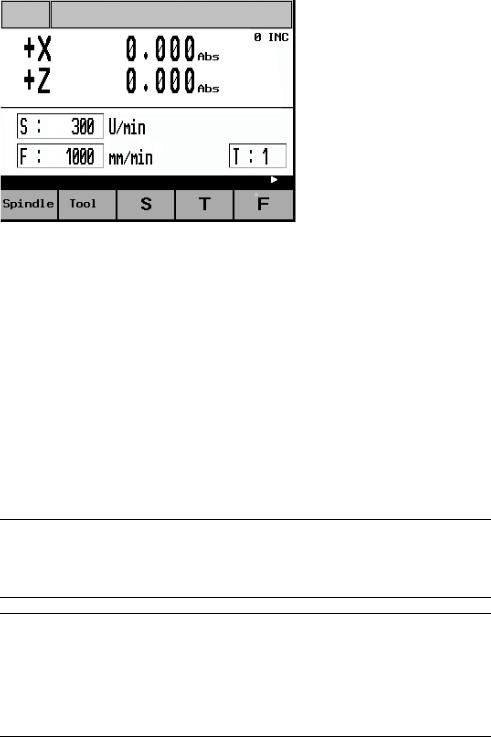
2.3 Manual Machining
The main Manual Machining screen looks like this:
Fig. 2-4: Main "Manual Machining" screen
Manual workpiece machining is carried out in this operating mode.
Here the cross-slide is controlled either
•By means of the handwheels for the X and Z axis (→ Machining with the handwheels) or
•By means of the 4-way switch or the axis direction keys (X+/X-/Z+/Z-) (→ Machining with the 4-way switch/axis direction keys)
The spindle is controlled by means of
•The spindle joystick or the individual spindle advance and spindle reverse keys (→ Spindle advance/reverse).
Machining technology data such as spindle speed, cutting speed and feedrate must be set via special screen forms.
→Machining technology data.
!Note
Generally speaking the relevant machining technology data must be entered before starting manual machining.
Caution
The maximum permissible spindle speed, which depends on the chucking device fitted, must be entered in the Machining Technology Data screen form!
Failure to pay sufficient attention to this point can lead to serious damage as a result of the chucking device speed being exceeded.
→ Machining technology data.
© Siemens AG, 2005. All rights reserved |
2-17 |
SINUMERIK 802S/C BA_MM (BA) – 04/2005 Edition |
2 Sequence of Operations |
04/2005 |
2.3 Manual Machining |
|
2.3.1 Displays on the main "Manual Machining" screen:
Actual-value |
The current actual position for the X and Z axis is shown here. |
display: |
If the abbreviation "Abs" appears after the position value, the |
|
display shows the absolute machine position. If the |
|
abbreviation "Rel" appears here, however, it is a relative |
|
position reflecting the distance traversed since the display was |
|
last reset. |
|
→ Toggling the display. |
Traversing |
If the axis is moving, the current traversing direction is indicated |
direction: |
by the appropriate sign (+/-) in front of the axis letter (X/Z). |
S value: |
The programmed value for either the spindle speed (Rev/min) |
|
or the cutting speed (m/min) is shown here. The display |
|
corresponds to the settings for the machining technology data. |
|
→ Machining technology data. |
F value: |
The programmed feedrate is displayed here in either "m/min" or |
|
"mm/Rev", depending on the settings for the machining |
|
technology data. |
|
→ Machining technology data. |
T value: |
The tool offset used by the controller is shown here. |
|
→ Tool change. |
INC value: |
Indicates the handwheel pulse weighting currently set. |
|
→ Machining with the handwheels |
2-18 |
© Siemens AG, 2005. All rights reserved |
SINUMERIK 802S/C BA_MM (BA) – 04/2005 Edition |
04/2005 |
2 Sequence of Operations |
|
|
2.3 Manual Machining |
|
2.3.2 Toggling the display
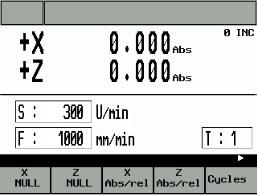
The radius turning function is accessed from the main "Manual Machining" screen (Fig. 4) as follows:
• Change the function key bar by pressing the "Extended menu" key  twice:
Fig. 2-5: Main service “toggling the display”
Press the function keys shown to alter the display as follows:
“X NULL”: Press the "X=0" or "Z=0" key to change the actual value display to "relative position display" and reset the display in the corresponding axis.
“Z NULL”: |
Press the "X=0" or "Z=0" key to change the actual value display |
|
to "relative position display" and reset the display in the |
|
corresponding axis. |
"X Abs./rel.”: |
Press the "abs./rel." key to toggle the actual value display |
|
between "absolute position display" and "relative position |
|
display" in the corresponding axis. |
"Z Abs./rel.”: |
Press the "abs./rel." key to toggle the actual value display |
|
between "absolute position display" and "relative position |
|
display" in the corresponding axis. |
© Siemens AG, 2005. All rights reserved |
2-19 |
SINUMERIK 802S/C BA_MM (BA) – 04/2005 Edition |

2 Sequence of Operations |
04/2005 |
2.3 Manual Machining |
|
2.3.3 Machining with the handwheels
The handwheels for the X and Z axis are not mechanically connected to the feed screws. Electronic pulse generators mounted on the handwheels generate the information needed by the controller to execute the required traversing movement.
The handwheels are only active when the 4-way switch is in the zero position and the individual axis control keys are disabled.
The distance traversed per handwheel pulse depends on the handwheel valuation setting.
→Handwheel valuation setting.
!Note
If the handwheel valuation is set to "0" or if the feedrate override switch is in the "0" position, the handwheels are disabled.
2.3.4Handwheel valuation setting
Press the “Toggle key for handwheel valuation” in the main “Manual Machining” screens to set the handwheel valuation.
The current setting will appear on the top-right of the screen (e.g., 100 INC).
If you are unable to adjust the handwheel valuation setting, it will be because the controller's internal mode is incompatible with this process. Press the “JOG” key once to resolve the problem.
Caution
An incorrect handwheel valuation setting can result in damage to the workpiece, tool and machine.
2.3.5 Machining with the 4-way switch/axis direction keys
The axis can be traversed in the desired direction by turning the 4-way switch or pressing the appropriate axis direction key. The feedrate at which the axis is traversed depends on the settings in the Machining Technology Data screen form.
The axis feedrate is also influenced by the feedrate override switch setting and, depending on the option selected in the Machining Technology Data screen form (Rev. feedrate/cutting speed), by the spindle override switch.
2-20 |
© Siemens AG, 2005. All rights reserved |
SINUMERIK 802S/C BA_MM (BA) – 04/2005 Edition |
04/2005 |
2 Sequence of Operations |
|
|
2.3 Manual Machining |
|
If rapid traverse overlay is also actuated, the axis is moved at the maximum possible speed unless a different value has been set at the feedrate override switch.
!Note
If the feedrate override switch is set to "0", any type of axis movement is blocked. With the "Rev. feedrate" and "cutting speed" settings, the feed is blocked until the spindle reaches the setpoint speed.
2.3.6Spindle advance/reverse
The spindle is started in the appropriate direction (spindle advance/reverse) by moving the spindle joystick or actuating the corresponding spindle direction key, provided that the chuck guard switch is enabled (chuck guard closed).
!Note
The spindle cannot be started unless the chuck guard switch is enabled. → Close the chuck guard.
Caution
Handling the chuck guard/chuck guard switch can lead to injury or mechanical damage and should be avoided.
When the spindle is switched off it brakes and comes to a halt. If a spindle brake is fitted, it is applied. If there is no spindle brake or it is switched off, the spindle can be rotated freely once it has stopped.
If "Spindle Positi." is selected in the "Spindle Positioning" screen form, the spindle is moved to the specified position after being switched off.
The spindle brake, if fitted, is then applied. → Spindle positioning.
The programmed spindle speed can be controlled by means of an appropriate spindle override switch setting (e.g. 50%).
2.3.7 Jog spindle
The jog spindle key (if provided by the machine manufacturer) can be used to rotate the spindle at low speed, for example to move a workpiece to a specific angular position.
© Siemens AG, 2005. All rights reserved |
2-21 |
SINUMERIK 802S/C BA_MM (BA) – 04/2005 Edition |

2 Sequence of Operations |
04/2005 |
2.3 Manual Machining |
|
2.3.8 Tool change
In the case of conventional/cycle-controlled machines of this order of magnitude, with just a few exceptions, a manual tool change will generally be required. For this reason, the correct tool number (tool compensation) must be notified to the control by hand once the real tool change has taken place at the machine.
This is done as follows:
•Press function key "T" in the main Manual Machining screen form.
•The entry field for the T value is highlighted.
•Use the numeric keypad to enter the required tool number (tool offset) (permissible values 1-15).
•Press "Enter" to complete the process.
If no further messages appear, the controller has completed the tool change.
!Note
The tool number (tool offset) can only be changed, if all axes and the spindle are stationary.
Caution
The tool number (tool offset) entered in the T value field must correspond to the tool fitted in the machine. Otherwise, the tool will have to be re-calibrated (→ Tool calibration). An uncalibrated or incorrectly calibrated tool can lead to dimensional errors or to incorrect cutting values.
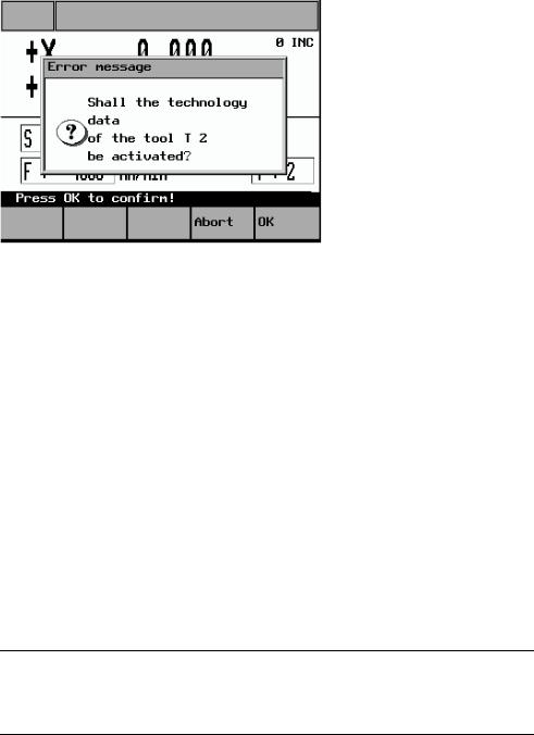
If machining technology data settings for the tool number (tool offset) to be activated are found in the “Tool Data” screen form (→ Entering tool technology data), the following message appears (relating to T4, in this example):
2-22 |
© Siemens AG, 2005. All rights reserved |
SINUMERIK 802S/C BA_MM (BA) – 04/2005 Edition |
04/2005 |
2 Sequence of Operations |
|
|
2.3 Manual Machining |
|
Fig. 2-6: Tool technology data acceptance message
The question can be answered by pressing one of these function keys:
"OK" |
The tool offsets for the X and Z axis corresponding to the last tool |
|
calibration operation are applied. The actual-value display changes, |
|
if necessary. |
|
The previous machining technology data is also overwritten by the |
|
tool technology data (which has been saved for this tool) (feedrate, |
|
spindle speed, cutting speed) |
|
→ Entering tool technology data. |
“Abort” |
The tool offsets for the X and Z axis corresponding to the last tool |
|
calibration operation are applied. The actual-value display changes, |
|
if necessary. |
|
The previous machining technology data is retained. |
2.3.9 Machining technology data
Machining technology data, such as spindle speed, cutting speed and feedrate, defines the settings that the controller needs for the machining of workpieces.
!Note
The machining technology data can only be changed, if all axes and the spindle are stationary.
There are two ways of changing the machining technology data:
•Simple changes to the spindle and feedrate values (S value/F value) can be made directly in the "Manual Machining" screen form.
→ Changing the spindle/feedrate value
© Siemens AG, 2005. All rights reserved |
2-23 |
SINUMERIK 802S/C BA_MM (BA) – 04/2005 Edition |

2 Sequence of Operations |
04/2005 |
2.3Manual Machining
•A separate screen form is provided for entering the full set of machining technology data.
→ Entering machining technology data
2.3.10 Changing the spindle/feedrate value
This method of adapting technology data can be used to change values quickly during machining.
The values are changed using the appropriate function keys in the "Manual Machining" screen form.
However, it is not possible to switch between "m/min" and "rev/min" (spindle) or "mm/min" and "mm/rev" (axis) here (→ Entering machining technology data).
Changing |
Press function key "S" to highlight the display field showing the |
the S |
current programmed spindle value. The programmed value can now |
value: |
be changed via the numeric keypad. Then press Enter to accept |
|
(activate) the change. The entry field is deselected and the process |
|
is complete. |
|
To abort the change, press function key "S" or the Alarm reset key |
|
instead of Enter. In this case the entry field is again deselected, the |
|
new value is cleared and the previously programmed spindle value |
|
is restored. |
|
You cannot switch between "m/min" and "rev/min" here. |
Changing |
Press function key "F" to highlight the display field showing the |
the F |
current programmed feedrate value. The programmed value can |
value: |
now be changed via the numeric keypad. Then press Enter to |
|
accept (activate) the change. The entry field is deselected and the |
|
process is complete. |
|
To abort the change, press function key "F" or the Alarm reset key |
|
instead of Enter. In this case the entry field is again deselected, the |
|
new value is cleared and the previously programmed feedrate value |
|
is restored. |
|
You cannot switch between "mm/min" and "mm/rev" here. |
!Note
The S value or F value can only be changed if all axes and the spindle are stationary.
2-24 |
© Siemens AG, 2005. All rights reserved |
SINUMERIK 802S/C BA_MM (BA) – 04/2005 Edition |
04/2005 |
2 Sequence of Operations |
|
|
2.3 Manual Machining |
|
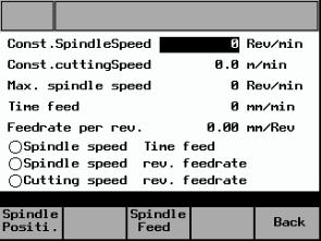
2.3.11 Entering machining technology data:
To open the screen form for machining technology data, press the "Spindle" function key in "Manual Machining".
The following screen form appears:
Fig. 2-7: Machining technology data input
When the screen form appears, the last entry field to have been edited is highlighted and a new value can be entered. To change a value in a different entry field, use the cursor keys to move to that field. Enter the value via the numeric keypad and then press Enter to accept (activate) the value. To abort the change and restore the previous entry value, use the cursor keys to move to a different entry field or exit the screen form (by pressing the "Back" function key), without pressing Enter.
The meanings of the individual entry fields are defined as follows:
Const. Spindle |
This entry value defines the programmed spindle speed for |
Speed |
machining with "Spindle speed + Time feed" or "Spindle |
|
speed + Rev. feedrate". The value is only fully reached if no |
|
reduction is specified via the spindle override valuation or the |
|
spindle speed limit parameter ("Max. spindle speed"). |
Const. cutting |
Cutting speed entry value for machining with "Cutting speed + |
Speed |
Rev. feedrate". The spindle speed is adjusted to the |
|
machining diameter of the workpiece so that uniform cutting |
|
conditions are achieved. Since the spindle would theoretically |
|
have to rotate at an "infinitely high" speed at the rotational |
|
center point in this mode, it has to be limited via the "Max. |
|
spindle speed" parameter. The constant cutting speed can |
|
also be influenced by means of the feedrate and spindle |
|
override valuation settings. |
© Siemens AG, 2005. All rights reserved |
2-25 |
SINUMERIK 802S/C BA_MM (BA) – 04/2005 Edition |

2 Sequence of Operations |
04/2005 |
2.3 Manual Machining |
|
Max. spindle |
It is vital to enter the maximum permissible spindle speed |
speed |
here. The spindle speed is then limited to this value under all |
|
circumstances, so that the permissible chucking device |
|
speed, for example, cannot be exceeded. |
Time feed |
If Time feed is selected, the axes are moved at the speed |
|
entered here (mm/min) (unless rapid traverse override is |
|
activated). It can be influenced by the feedrate override |
|
switch setting. |
Feedrate per |
The value entered here determines the axis velocity in |
rev. |
“Spindle speed + Rev. feedrate” or “Const. cutting speed + |
|
Rev. feedrate” modes (if no rapid traverse override is set). It |
|
is influenced directly by the feedrate override valuation setting |
|
and indirectly by the spindle override valuation setting. |
Caution
In the entry field for the maximum permissible spindle speed, you must enter the value specified by the manufacturer for the chucking device that is fitted! Failure to pay sufficient attention to this point can lead to serious damage as a result of the chucking device speed being exceeded.
•To select the desired machining mode, press the "Spindle Feed" function key one or more times:
"Spindle speed + Time feed" → "Spindle speed + Rev. feedrate" → "Cutting speed + Rev. feedrate"
The symbols displayed next to the text have the following meaning:
Display: |
Machining mode deselected |
|
Machining mode active (selected) |
2-26 |
© Siemens AG, 2005. All rights reserved |
SINUMERIK 802S/C BA_MM (BA) – 04/2005 Edition |
04/2005 |
2 Sequence of Operations |
|
|
2.3 Manual Machining |
|
2.3.12 Spindle positioning
The Spindle positioning function is intended purely for stopping the spindle in a specific position to facilitate fitting of the chuck guard. It is not intended for positionrelated machining.
If the Spindle positioning function is selected, the spindle is switched off and then moved to the position specified in the "Set spindle pos." entry field. If fitted, a spindle brake is then applied.
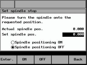
To open the “Spindle Positioning” screen form, press the "Spindle Positi." function key in the "Machining Technology Data" screen form.
The following screen form appears:
Fig. 2-8: Spindle positioning
When the screen form appears, there are two ways to enter the position:
•Use the numeric keypad to enter the position directly in the highlighted entry field for the "Set spindle pos.". Then press Enter to accept the value. Only values from 0 to 359.9 are permitted; otherwise, an error message appears and the value is not accepted.
•After switching off the spindle, rotate it manually into the required position and press Enter. The current spindle position is displayed in the "Set spindle pos." entry field and automatically accepted. If the spindle has not completed a full rotation since the controller was last powered up, the spindle is not yet synchronized and the position will therefore not be accepted. In this case, a corresponding message is displayed.
© Siemens AG, 2005. All rights reserved |
2-27 |
SINUMERIK 802S/C BA_MM (BA) – 04/2005 Edition |

2 Sequence of Operations |
04/2005 |
2.3 Manual Machining |
|
Press "ON" to activate spindle positioning and "OFF" to deactivate it.
The current status is indicated as shown below:
Display: |
Function deselected |
|
Function active (selected) |
2-28 |
© Siemens AG, 2005. All rights reserved |
SINUMERIK 802S/C BA_MM (BA) – 04/2005 Edition |
04/2005 |
3 Tool Data |
|
|
3.1 Tool list |
|
3
3 Tool Data
3.1 |
Tool list.......................................................................................... |
3-30 |
3.2 |
Tool calibration.............................................................................. |
3-31 |
3.3 |
Geometry tool data ....................................................................... |
3-32 |
3.4 |
Entering tool technology data ....................................................... |
3-33 |
3.5 |
Deleting tool technology data ....................................................... |
3-35 |
© Siemens AG, 2005. All rights reserved |
3-29 |
SINUMERIK 802S/802C BA_MM (BA) – 04/2005 Edition |
3 Tool Data |
04/2005 |
3.1 Tool list |
|
3.1 Tool list
The controller is supplied with a tool list for 15 tools as standard. However, the individual tools must be calibrated prior to initial use.
→ Tool calibration.
Caution
An uncalibrated or incorrectly calibrated tool can lead to dimensional errors or to incorrect cutting values! If the values entered are very different from the actual tool values, there is a risk that the tool may break or the mechanism or workpiece may be damaged.
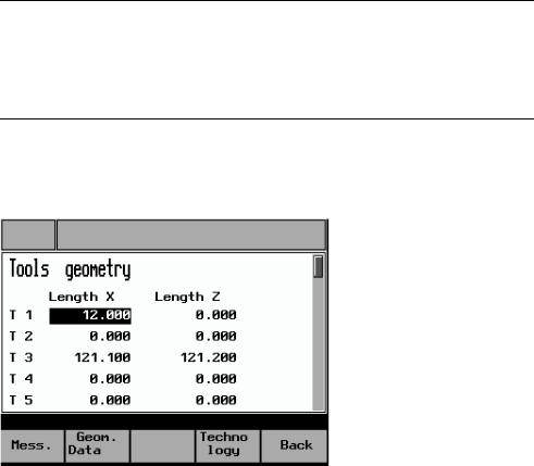
To open the "Tool Data Overview", press the "Tool" function key in the main "Manual Machining" screen form.
The following screen form appears:
Fig. 3-1: Tool data overview
The active offsets for each tool, known as the tool offsets for the X and Z axis, are displayed in this screen form. Experienced lathe operators can use this screen form to enter the tool offsets, as on CNC controllers. Other operators should simply refer to this screen form for information about the current offsets. The actual tool measuring process takes place in the "Tool Measuring" screen form.
→ Tool calibration.
Data can be entered in the "Tool Data Overview" as follows:
•Use the cursor keys to select the required field (field is highlighted)
•Select the required tool type (turning tool or drilling tool) by pressing the "Turn-/Boretool" function key
•Enter the values and press Enter to accept. The actual value display on the machine (in "Manual Machining") is now updated to reflect the change. If you do not wish to accept the value entered, either use the cursor key to leave the entry field or switch to another screen form without pressing Enter.
3-30 |
© Siemens AG, 2005. All rights reserved |
SINUMERIK 802S/802C BA_MM (BA) – 04/2005 Edition |
Loading...