


802S

Operating and Programming 01/2002 Edition
Milling
SINUMERIK 802S/802C


SINUMERIK 802S
Introduction 1
Power ON 2
SINUMERIK 802C
Operation and Programming
Milling
Setup 3
Manually Controlled
Operation
Automatic Mode 5
Part Programming 6
4
Valid for
Control System Software Version
SINUMERIK 802S 3
SINUMERIK 802C 3
01.2002 Edition
Services and Diagnosis 7
Programming 8
Cycles 9

3ls
SINUMERIKDocumentation
Printing history
Brief details of this edition and previous editions are listed below.
IThe status of each edition is shown by the code in the ”Remarks” column.
Status code in the “Remarks” column:
A New documentation.. . . . .
B Unrevised reprint with new Order No.. . . . .
C Revised edition with new status. . . . . .
If actual changes have been made on the page since the last edition,
this is indicated by a new edition coding in the header on the page.
Edition Order–No. Remark
02.99 6FC5598–2AA10–0BP1 A
04.00 6FC5598–3AA10–0BP1 C
01.02 6FC5598–3AA10–0BP2 C
This Manual is included on the documentation on CD–ROM (DOCONCD)
Edition Order–No. Remark
11.02 6FC5298–6CA00–0BG3 C
Trademarks
SIMATICr, SIMATIC HMIr, SIMATIC NETr, SIROTECr, SINUMERIKr and SIMODRIVEr are registered
trademarks of Siemens. Third parties using for their own purposes any other names in this document which
refer to trademarks might infringe upon the rights of trademark owners.
This publication was produced with Interleaf V 7
The reproduction, transmission or use of this document or its
contents is not permitted without express written authority. Offenders
will be liable for demages. All rights, including rights created by patent
grant or registration of utility model or design, are reserved.
Siemens AG 2002. All rights reserved.
Printed in the Federal Republic of Germany
Other functions not described in this documentation might be
executable in the control. This does not, however, represent an
obligation to supply such functions with a new control or when
servicing.
We have checked that the contents of this document correspond to
the hardware and software described. Nonetheless, differences might
exist and therefore we cannot guarantee that they are completely
identical. The information contained in this document is, however,
reviewed regularly and any necessary changes will be included in the
next edition. We welcome suggestions for improvement.
Subject to change without prior notice.
Siemens–AktiengesellschaftBestell–Nr. 6FC5598–3AA10–0BP2

Safety notices
!
!
!
This Manual contains notices intended to ensure your personal safety and to avoid material damage. The notices
are highlighted by a warning triangle and, depending on the degree of hazard, represented as shown below:
Danger
indicates that loss of life, severe personal injury or substantial material damage will result if the appropriate pre-
cautions are not taken.
Warning
indicates that loss of life, severe personal injury or substantial material damage may result if the appropriate pre-
cautions are not taken.
Caution
indicates that minor personal injury or material damage may result if the appropriate precautions are not taken.
Caution
without a warning triangle means that a material damage can occur if the appropriate precau-
tions are not taken.
Attention
means that an undesirede event or status can occur if the appropriate note is not observed.
Note
is used to draw your special attention to an important information on the product, the handling of the product or the
corresponding part of the documentation.
Qualified personnel
Start–up and operation of a device may only be carried out by qualified personnel. Qualified personnel as referred to in the safety notices provided in this Manual are persons who are authorized to start up, ground and tag
devices, systems and circuits according to the relevant safety standards.
Usage as per intended purpose
Please observe the following:
Warning
!
The device may only be used for the cases of application, as intended by the Catalog, and only in conjunction with
third–party devices and components recommended or approved by Siemens.
The proper and safe operation of the product requires transport, storage and installation according to the relevant
instructions and qualified operation and maintenance at the prescribed intervals.
SINUMERIK 802S/802C
6FC5 598–3AA10–0BP2 (01.02) (OP–M)
v

Table of Contents
1 Introduction 1-11. . . . . . . . . . . . . . . . . . . . . . . . . . . . . . . . . . . . . . . . . . . . . . . . . . . . . . . . . . . . . . . . . .
1.1 Screen Layout 1-11. . . . . . . . . . . . . . . . . . . . . . . . . . . . . . . . . . . . . . . . . . . . . . . . . . . . . . . . . . . . . . . .
1.2 Operating areas 1-14. . . . . . . . . . . . . . . . . . . . . . . . . . . . . . . . . . . . . . . . . . . . . . . . . . . . . . . . . . . . . .
1.3 Overview of the most important softkey functions 1-15. . . . . . . . . . . . . . . . . . . . . . . . . . . . . . . . . .
1.4 Pocket calculator 1-16. . . . . . . . . . . . . . . . . . . . . . . . . . . . . . . . . . . . . . . . . . . . . . . . . . . . . . . . . . . . . .
1.5 Basic principles 1-22. . . . . . . . . . . . . . . . . . . . . . . . . . . . . . . . . . . . . . . . . . . . . . . . . . . . . . . . . . . . . . .
2 Turning On and Reference Point Approach 2-25. . . . . . . . . . . . . . . . . . . . . . . . . . . . . . . . . . . . .
3 Setup 3-27. . . . . . . . . . . . . . . . . . . . . . . . . . . . . . . . . . . . . . . . . . . . . . . . . . . . . . . . . . . . . . . . . . . . . . . .
3.1 Entering tools and tool offsets 3-27. . . . . . . . . . . . . . . . . . . . . . . . . . . . . . . . . . . . . . . . . . . . . . . . . . .
3.2 Creating a new tool 3-28. . . . . . . . . . . . . . . . . . . . . . . . . . . . . . . . . . . . . . . . . . . . . . . . . . . . . . . . . . . .
3.3 Tool compensation data 3-29. . . . . . . . . . . . . . . . . . . . . . . . . . . . . . . . . . . . . . . . . . . . . . . . . . . . . . . .
3.4 Determining the tool offsets 3-30. . . . . . . . . . . . . . . . . . . . . . . . . . . . . . . . . . . . . . . . . . . . . . . . . . . . .
3.5 Entering/modifying zero offsets 3-32. . . . . . . . . . . . . . . . . . . . . . . . . . . . . . . . . . . . . . . . . . . . . . . . . .
3.6 Determining the zero offset 3-34. . . . . . . . . . . . . . . . . . . . . . . . . . . . . . . . . . . . . . . . . . . . . . . . . . . . .
3.7 Programming the setting data – “Parameters” operating area 3-36. . . . . . . . . . . . . . . . . . . . . . . .
3.8 R parameters - “Parameters” operating area 3-38. . . . . . . . . . . . . . . . . . . . . . . . . . . . . . . . . . . . . .
4 Manually Operated Mode 4-39. . . . . . . . . . . . . . . . . . . . . . . . . . . . . . . . . . . . . . . . . . . . . . . . . . . . . .
4.1 Jog mode - ”Machine” operating area 4-39. . . . . . . . . . . . . . . . . . . . . . . . . . . . . . . . . . . . . . . . . . . .
4.1.1 Assigning handwheels 4-41. . . . . . . . . . . . . . . . . . . . . . . . . . . . . . . . . . . . . . . . . . . . . . . . . . . . . . . . .
4.2 MDA Mode (Manual Data Input) - “Machine” operating area 4-43. . . . . . . . . . . . . . . . . . . . . . . . .
5 Automatic Mode 5-45. . . . . . . . . . . . . . . . . . . . . . . . . . . . . . . . . . . . . . . . . . . . . . . . . . . . . . . . . . . . . .
5.1 Selecting/starting a part program - “Machine” operating area 5-48. . . . . . . . . . . . . . . . . . . . . . . .
5.2 Block search - “Machine” operating area 5-49. . . . . . . . . . . . . . . . . . . . . . . . . . . . . . . . . . . . . . . . . .
5.3 Stopping/cancelling a part program - “Machine” operating area 5-49. . . . . . . . . . . . . . . . . . . . . .
5.4 Repositioning after interruption 5-50. . . . . . . . . . . . . . . . . . . . . . . . . . . . . . . . . . . . . . . . . . . . . . . . . .
5.5 Program execution from external (V.24 interface) 5-51. . . . . . . . . . . . . . . . . . . . . . . . . . . . . . . . . .
5.6 Teach In 5-52. . . . . . . . . . . . . . . . . . . . . . . . . . . . . . . . . . . . . . . . . . . . . . . . . . . . . . . . . . . . . . . . . . . . .
6 Part Programming 6-55. . . . . . . . . . . . . . . . . . . . . . . . . . . . . . . . . . . . . . . . . . . . . . . . . . . . . . . . . . . .
6.1 Entering a new program - “Program” operating area 6-57. . . . . . . . . . . . . . . . . . . . . . . . . . . . . . . .
6.2 Editing part programs - “Program” operating area 6-58. . . . . . . . . . . . . . . . . . . . . . . . . . . . . . . . . .
6.3 Programming support 6-61. . . . . . . . . . . . . . . . . . . . . . . . . . . . . . . . . . . . . . . . . . . . . . . . . . . . . . . . . .
6.3.1 Vertical menu 6-61. . . . . . . . . . . . . . . . . . . . . . . . . . . . . . . . . . . . . . . . . . . . . . . . . . . . . . . . . . . . . . . . .
6.3.2 Cycles 6-62. . . . . . . . . . . . . . . . . . . . . . . . . . . . . . . . . . . . . . . . . . . . . . . . . . . . . . . . . . . . . . . . . . . . . . .
6.3.3 Contour 6-63. . . . . . . . . . . . . . . . . . . . . . . . . . . . . . . . . . . . . . . . . . . . . . . . . . . . . . . . . . . . . . . . . . . . . .
6.3.4 Free softkey assignment 6-79. . . . . . . . . . . . . . . . . . . . . . . . . . . . . . . . . . . . . . . . . . . . . . . . . . . . . . .
7 Services and Diagnosis 7-81. . . . . . . . . . . . . . . . . . . . . . . . . . . . . . . . . . . . . . . . . . . . . . . . . . . . . . .
7.1 Data transfer via the V24 Interface 7-81. . . . . . . . . . . . . . . . . . . . . . . . . . . . . . . . . . . . . . . . . . . . . . .
7.1.1 Interface parameters 7-84. . . . . . . . . . . . . . . . . . . . . . . . . . . . . . . . . . . . . . . . . . . . . . . . . . . . . . . . . .
7.1.2 Special functions 7-85. . . . . . . . . . . . . . . . . . . . . . . . . . . . . . . . . . . . . . . . . . . . . . . . . . . . . . . . . . . . . .
7.1.3 Interface parameterization 7-85. . . . . . . . . . . . . . . . . . . . . . . . . . . . . . . . . . . . . . . . . . . . . . . . . . . . . .
vi
6FC5 598–3AA10–0BP2 (01.02) (OP–M)
SINUMERIK 802S/802C

7.2 Diagnosis and start–up - ”Diagnostics” operating area 7-87. . . . . . . . . . . . . . . . . . . . . . . . . . . . . .
8 Programming 8-99. . . . . . . . . . . . . . . . . . . . . . . . . . . . . . . . . . . . . . . . . . . . . . . . . . . . . . . . . . . . . . . .
8.1 Fundamentals of NC programming 8-99. . . . . . . . . . . . . . . . . . . . . . . . . . . . . . . . . . . . . . . . . . . . . .
8.1.1 Program structure 8-99. . . . . . . . . . . . . . . . . . . . . . . . . . . . . . . . . . . . . . . . . . . . . . . . . . . . . . . . . . . . .
8.1.2 Word structure and address 8-100. . . . . . . . . . . . . . . . . . . . . . . . . . . . . . . . . . . . . . . . . . . . . . . . . . . .
8.1.3 Block structure 8-100. . . . . . . . . . . . . . . . . . . . . . . . . . . . . . . . . . . . . . . . . . . . . . . . . . . . . . . . . . . . . . . .
8.1.4 Character set 8-102. . . . . . . . . . . . . . . . . . . . . . . . . . . . . . . . . . . . . . . . . . . . . . . . . . . . . . . . . . . . . . . . .
8.1.5 Overview of instructions 8-104. . . . . . . . . . . . . . . . . . . . . . . . . . . . . . . . . . . . . . . . . . . . . . . . . . . . . . . .
8.2 Position data 8-114. . . . . . . . . . . . . . . . . . . . . . . . . . . . . . . . . . . . . . . . . . . . . . . . . . . . . . . . . . . . . . . . .
8.2.1 Plane selection: G17 to G19 8-114. . . . . . . . . . . . . . . . . . . . . . . . . . . . . . . . . . . . . . . . . . . . . . . . . . . .
8.2.2 Absolute/incremental dimensions: G90, G91 8-115. . . . . . . . . . . . . . . . . . . . . . . . . . . . . . . . . . . . . .
8.2.3 Metric/inch dimensions: G71, G70 8-116. . . . . . . . . . . . . . . . . . . . . . . . . . . . . . . . . . . . . . . . . . . . . . .
8.2.4 Programmable zero offset and rotation: G158, G258, G259 8-117. . . . . . . . . . . . . . . . . . . . . . . . .
8.2.5 Workpiece clamping – settable zero offset:
G54 to G57, G500, G53 8-119. . . . . . . . . . . . . . . . . . . . . . . . . . . . . . . . . . . . . . . . . . . . . . . . . . . . . . . .
8.3 Axis movements 8-121. . . . . . . . . . . . . . . . . . . . . . . . . . . . . . . . . . . . . . . . . . . . . . . . . . . . . . . . . . . . . .
8.3.1 Linear interpolation at rapid traverse: G0 8-121. . . . . . . . . . . . . . . . . . . . . . . . . . . . . . . . . . . . . . . . .
8.3.2 Linear interpolation at feedrate: G1 8-122. . . . . . . . . . . . . . . . . . . . . . . . . . . . . . . . . . . . . . . . . . . . . .
8.3.3 Circular interpolation: G2, G3 8-123. . . . . . . . . . . . . . . . . . . . . . . . . . . . . . . . . . . . . . . . . . . . . . . . . . .
8.3.4 Circular interpolation via intermediate point: G5 8-126. . . . . . . . . . . . . . . . . . . . . . . . . . . . . . . . . . . .
8.3.5 Thread cutting with constant lead: G33 8-127. . . . . . . . . . . . . . . . . . . . . . . . . . . . . . . . . . . . . . . . . . .
8.3.6 Tapping with compensating chuck: G63 8-128. . . . . . . . . . . . . . . . . . . . . . . . . . . . . . . . . . . . . . . . . .
8.3.7 Thread interpolation: G331, G332 8-129. . . . . . . . . . . . . . . . . . . . . . . . . . . . . . . . . . . . . . . . . . . . . . .
8.3.8 Fixed–point approach: G75 8-131. . . . . . . . . . . . . . . . . . . . . . . . . . . . . . . . . . . . . . . . . . . . . . . . . . . . .
8.3.9 Reference point approach: G74 8-131. . . . . . . . . . . . . . . . . . . . . . . . . . . . . . . . . . . . . . . . . . . . . . . . .
8.3.10 Feedrate F 8-131. . . . . . . . . . . . . . . . . . . . . . . . . . . . . . . . . . . . . . . . . . . . . . . . . . . . . . . . . . . . . . . . . . .
8.3.11 Feed overrride for circles: G900, G901 8-132. . . . . . . . . . . . . . . . . . . . . . . . . . . . . . . . . . . . . . . . . . .
8.3.12 Exact stop / continuous–path operation: G9, G60, G64 8-133. . . . . . . . . . . . . . . . . . . . . . . . . . . . .
8.3.13 Dwell time: G4 8-136. . . . . . . . . . . . . . . . . . . . . . . . . . . . . . . . . . . . . . . . . . . . . . . . . . . . . . . . . . . . . . . .
8.4 Spindle movements 8-137. . . . . . . . . . . . . . . . . . . . . . . . . . . . . . . . . . . . . . . . . . . . . . . . . . . . . . . . . . .
8.4.1 Spindle speed S, directions of rotation 8-137. . . . . . . . . . . . . . . . . . . . . . . . . . . . . . . . . . . . . . . . . . .
8.4.2 Spindle speed limitation: G25, G26 8-137. . . . . . . . . . . . . . . . . . . . . . . . . . . . . . . . . . . . . . . . . . . . . .
8.4.3 Spindle positioning: SPOS 8-138. . . . . . . . . . . . . . . . . . . . . . . . . . . . . . . . . . . . . . . . . . . . . . . . . . . . .
8.5 Rounding, chamfer 8-139. . . . . . . . . . . . . . . . . . . . . . . . . . . . . . . . . . . . . . . . . . . . . . . . . . . . . . . . . . . .
8.6 Tool and tool offset 8-141. . . . . . . . . . . . . . . . . . . . . . . . . . . . . . . . . . . . . . . . . . . . . . . . . . . . . . . . . . . .
8.6.1 General notes 8-141. . . . . . . . . . . . . . . . . . . . . . . . . . . . . . . . . . . . . . . . . . . . . . . . . . . . . . . . . . . . . . . .
8.6.2 Tool T 8-142. . . . . . . . . . . . . . . . . . . . . . . . . . . . . . . . . . . . . . . . . . . . . . . . . . . . . . . . . . . . . . . . . . . . . . .
8.6.3 Tool offset number D 8-142. . . . . . . . . . . . . . . . . . . . . . . . . . . . . . . . . . . . . . . . . . . . . . . . . . . . . . . . . .
8.6.4 Selection of tool radius offset: G41, G42 8-146. . . . . . . . . . . . . . . . . . . . . . . . . . . . . . . . . . . . . . . . . .
8.6.5 Behavior at corners: G450, G451 8-148. . . . . . . . . . . . . . . . . . . . . . . . . . . . . . . . . . . . . . . . . . . . . . . .
8.6.6 Tool radius compensation OFF: G40 8-149. . . . . . . . . . . . . . . . . . . . . . . . . . . . . . . . . . . . . . . . . . . . .
8.6.7 Special cases of tool radius compensation 8-151. . . . . . . . . . . . . . . . . . . . . . . . . . . . . . . . . . . . . . . .
8.6.8 Example of tool radius compensation 8-153. . . . . . . . . . . . . . . . . . . . . . . . . . . . . . . . . . . . . . . . . . . .
8.7 Miscellaneous function M 8-154. . . . . . . . . . . . . . . . . . . . . . . . . . . . . . . . . . . . . . . . . . . . . . . . . . . . . .
8.8 Arithmetic parameters R 8-155. . . . . . . . . . . . . . . . . . . . . . . . . . . . . . . . . . . . . . . . . . . . . . . . . . . . . . .
8.9 Program branches 8-157. . . . . . . . . . . . . . . . . . . . . . . . . . . . . . . . . . . . . . . . . . . . . . . . . . . . . . . . . . . .
8.9.1 Labels – destination for program branches 8-157. . . . . . . . . . . . . . . . . . . . . . . . . . . . . . . . . . . . . . . .
8.9.2 Unconditional program branches 8-157. . . . . . . . . . . . . . . . . . . . . . . . . . . . . . . . . . . . . . . . . . . . . . . .
8.9.3 Conditional branches 8-158. . . . . . . . . . . . . . . . . . . . . . . . . . . . . . . . . . . . . . . . . . . . . . . . . . . . . . . . . .
8.9.4 Example of program with branches 8-160. . . . . . . . . . . . . . . . . . . . . . . . . . . . . . . . . . . . . . . . . . . . . .
8.10 Subroutine technique 8-161. . . . . . . . . . . . . . . . . . . . . . . . . . . . . . . . . . . . . . . . . . . . . . . . . . . . . . . . . .
9 Cycles 9-165. . . . . . . . . . . . . . . . . . . . . . . . . . . . . . . . . . . . . . . . . . . . . . . . . . . . . . . . . . . . . . . . . . . . . . .
9.1 General information about standard cycles 9-165. . . . . . . . . . . . . . . . . . . . . . . . . . . . . . . . . . . . . . . .
9.1.1 Overview of cycles 9-165. . . . . . . . . . . . . . . . . . . . . . . . . . . . . . . . . . . . . . . . . . . . . . . . . . . . . . . . . . . .
SINUMERIK 802S/802C
6FC5 598–3AA10–0BP2 (01.02) (OP–M)
vii

9.1.2 Error messages and error handlingin cycles 9-166. . . . . . . . . . . . . . . . . . . . . . . . . . . . . . . . . . . . . . .
9.2 Drilling cycles 9-168. . . . . . . . . . . . . . . . . . . . . . . . . . . . . . . . . . . . . . . . . . . . . . . . . . . . . . . . . . . . . . . . .
9.2.1 Drilling, spot facing – LCYC82 9-168. . . . . . . . . . . . . . . . . . . . . . . . . . . . . . . . . . . . . . . . . . . . . . . . . .
9.2.2 Deep hole drilling – LCYC83 9-170. . . . . . . . . . . . . . . . . . . . . . . . . . . . . . . . . . . . . . . . . . . . . . . . . . . .
9.2.3 Tapping without compensating chuck – LCYC84 9-174. . . . . . . . . . . . . . . . . . . . . . . . . . . . . . . . . . .
9.2.4 Tapping with compensating chuck – LCYC840 9-176. . . . . . . . . . . . . . . . . . . . . . . . . . . . . . . . . . . .
9.2.5 Boring – LCYC85 9-179. . . . . . . . . . . . . . . . . . . . . . . . . . . . . . . . . . . . . . . . . . . . . . . . . . . . . . . . . . . . .
9.3 Drilling patterns 9-181. . . . . . . . . . . . . . . . . . . . . . . . . . . . . . . . . . . . . . . . . . . . . . . . . . . . . . . . . . . . . . .
9.3.1 Drilling a row of holes – LCYC60 9-181. . . . . . . . . . . . . . . . . . . . . . . . . . . . . . . . . . . . . . . . . . . . . . . .
9.3.2 Hole circle – LCYC61 9-185. . . . . . . . . . . . . . . . . . . . . . . . . . . . . . . . . . . . . . . . . . . . . . . . . . . . . . . . . .
9.4 Milling cycles 9-187. . . . . . . . . . . . . . . . . . . . . . . . . . . . . . . . . . . . . . . . . . . . . . . . . . . . . . . . . . . . . . . . .
9.4.1 Cutting square pockets, slots and circular pockets – LCYC75 9-187. . . . . . . . . . . . . . . . . . . . . . . .
viii
6FC5 598–3AA10–0BP2 (01.02) (OP–M)
SINUMERIK 802S/802C
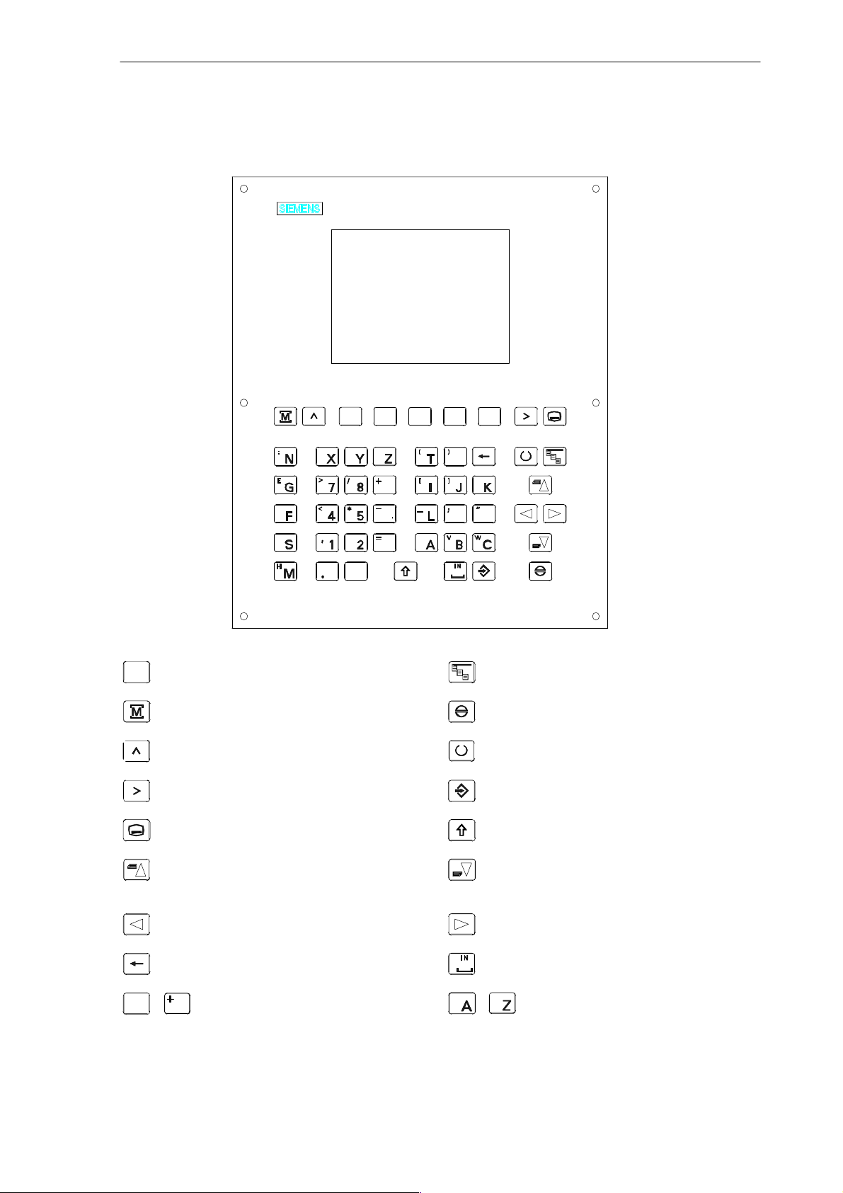
SINUMERIK 802S Slimline Operator Panel OP
D
9
O
Q
6
3
$
0
P
R
U
S
Softkey
Machine area key
Recall key
ETC key
Area switchover key
Cursor UP
with shift: page up
Cursor LEFT
S
Delete key (backspace)
$
0
9
Numerical keys
shift for alternative assignment
U
Alphanumeric keys
Vertical menu
Acknowledge alarm
Selection key/toggle key
ENTER / input key
Shift key
Cursor DOWN
with shift: page down
Cursor RIGHT
SPACE (INSERT)
shift for alternative assignment
SINUMERIK 802S/802C
6FC5 598–3AA10–0BP2 (01.02) (OP–M)
ix
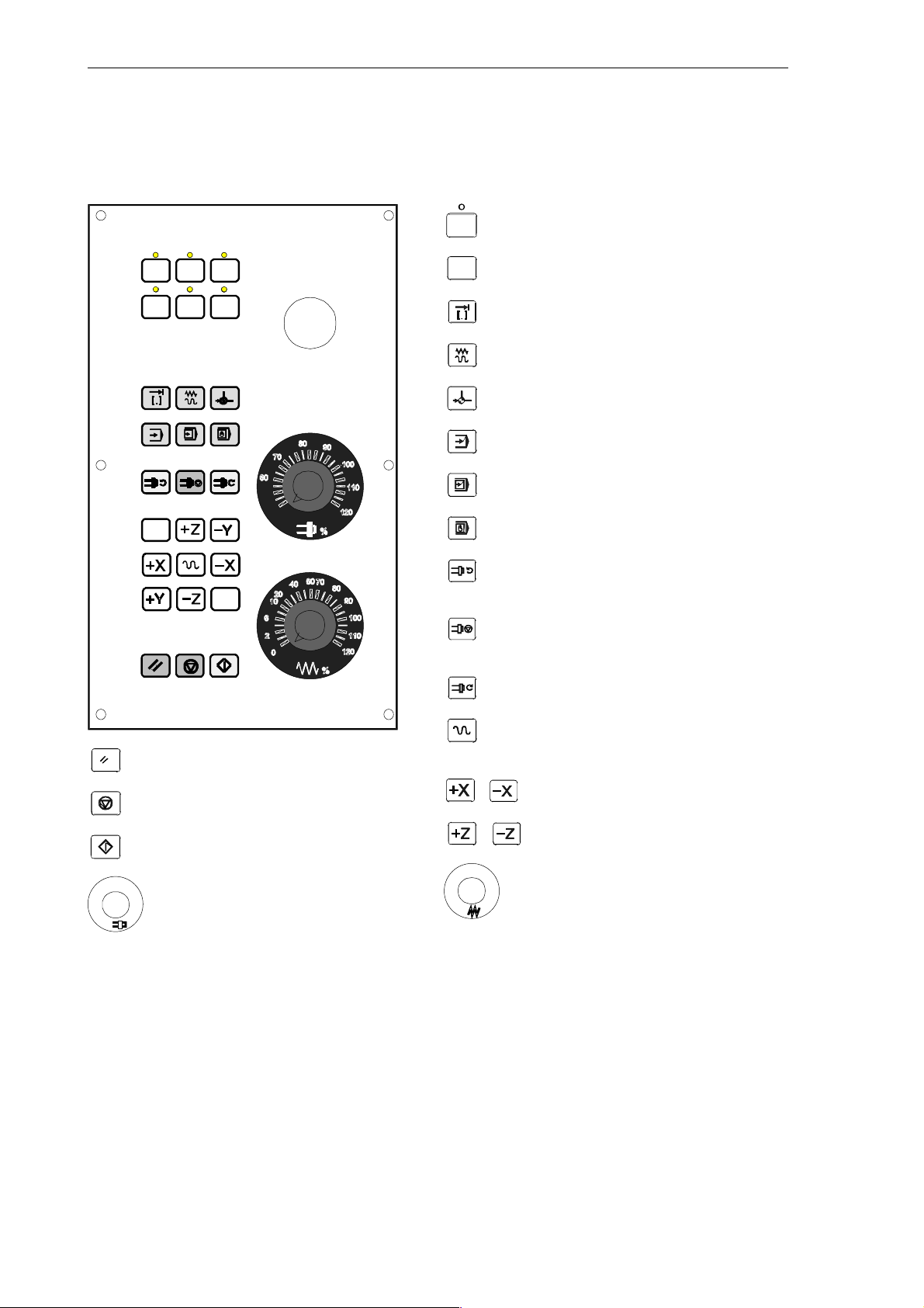
External Machine Control Panel
User–defined key with LED
User–defined key without LED
INCREMENT
JOG
REFERENCE POINT
AUTOMATIC
SINGLE BLOCK
MANUAL DATA
SPINDLE START LEFT
Counterclockwise direction
SPINDLE START RIGHT
Clockwise direction
SPINDLE STOP
RAPID TRAVERSE OVERLAY
RESET
NC STOP
X axis
NC START
Z axis
%
%
Spindle Speed Override
Feed Rate Override
(optional)
x
6FC5 598–3AA10–0BP2 (01.02) (OP–M)
SINUMERIK 802S/802C
Introduction
1.1 Screen Layout
1
1 2 3 4
5
8
9
11
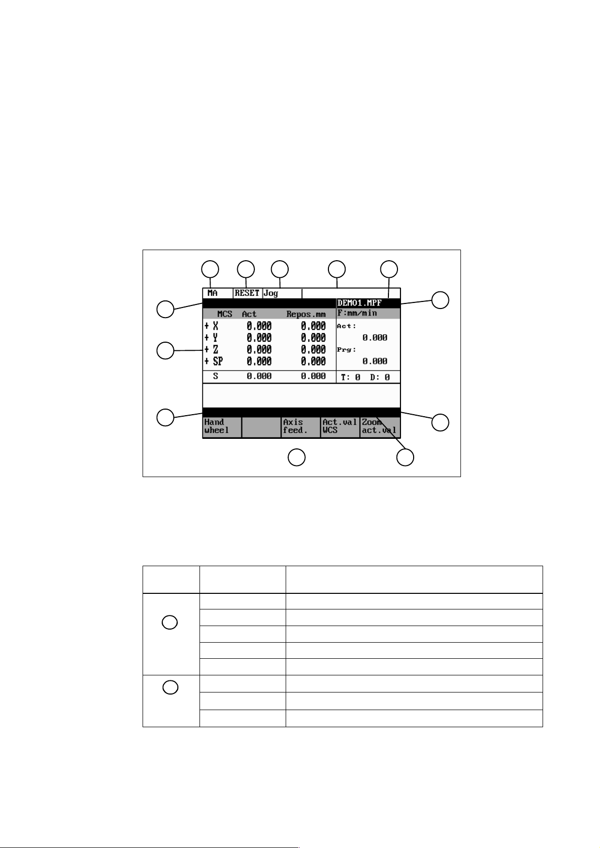
Fig. 1-1 Screen layout
The abbreviations on the screen stand for the following:
Table 1-1 Explanation of display elements
7
6
10
12
Display
Element
1
1
Active operating area
2
2
Program
status
SINUMERIK 802S/802C
6FC5 598–3AA10–0BP2 (01.02) (OP–M)
Abbreviation Meaning
MA Machine
PA Parameter
PR Programming
DI Services
DG Diagnosis
STOP Programm stopped
RUN Program running
RESET Program aborted
1-11

Introduction
1.1 Screen Layout
Table 1-1 Explanation of display elements
Display
Element
3
3
Operating
mode
4
Status
display
MeaningAbbreviation
Jog Manual traverse
MDA Manual input with automatic function
Auto Automatic
SKP Skip block
Program blocks marked by a slash in front of the block
number are ignored during program execution.
DRY Dry run feed
Traversing movements are executed at the feed specified
in the Dry Run Feed setting data.
ROV Rapid traverse override
The feed override also applies to rapid feed mode.
SBL Single block with stop after each block
When this function is active, the part program blocks are
processed separately in the following manner:
Each block is decoded separately, the program is stopped
at the end of each block. The only exception are thread
blocks without dry run feed. In this case, the program is
stopped only when the end of the current thread block is
reached. SBL can only be selected in the RESET state.
M1 Programmed stop
When this function is active, the program is stopped at
each block in which the miscellaneous function M01 is
programmed.
In this case, the message “5 stop M00/M01 active“ appears on the screen.
PRT Program test
1...1000 INC Incremental mode
If the control is in the Jog mode, incremental dimension is
displayed instead of the active program control function.
1-12
6FC5 598–3AA10–0BP2 (01.02) (OP–M)
SINUMERIK 802S/802C
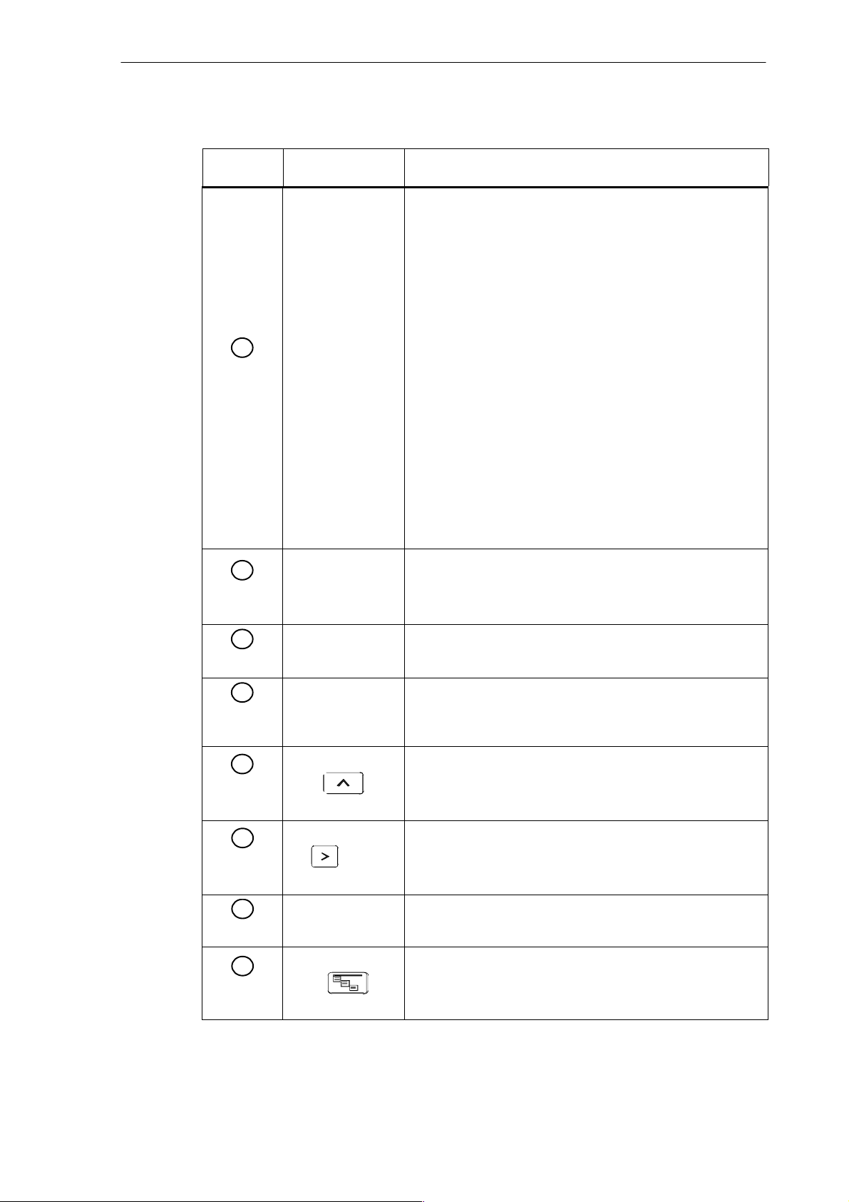
Table 1-1 Explanation of display elements
Introduction
1.1 Screen Layout
Display
Element
5
Operational
messages
6
10
11
12
13
14
15
16
17
18
19
20
21
22
23
MeaningAbbreviation
1
2
3
4
5
6
7
8
9
Stop: No NC Ready
Stop: EMERGENCY STOP active
Stop: Alarm active with stop
Stop: M0/M01 sctive
Stop: Block ended in SBL mode
Stop: NC STOP active
Wait: Read–in enable missing
Wait: Feed enable missing
Wait: Dwell time active
Wait: Auxiliary function acknowl. missing
Wait: Axis enable missing
Wait: Exact stop not reached
Wait: For spindle
Wait: Feed override to 0%
Stop: NC block incorrect
Wait: Block search active
Wait: No spindle enable
Wait: Axis feed value 0
Program
name
7
Alarm line
8
Working
window
9
Recall
symbol
10
Menu
extension
11
Softkey bar
12
Vertical
menu
The alarm line is only displayed if an NC or PLC alarm is active. The alarm line contains the alarm number and reset criterion of the most recent alarm.
Working window and NC display
This symbol is displayed above the softkey bar when the operator is in a lower–level menu.
When the Recall key is pressed, you can return to the next–
higher menu without saving data.
ETC is possible
If this symbol appears above the softkey bar, further menu
functions are provided. These functions can be activated
by the ETC key.
If this symbol is displayed above the softkey bar, further menu
functions are provided. When the VM key is pressed, these
functions appear on the screen and can be selected by Cursor UP and Cursor DOWN.
SINUMERIK 802S/802C
6FC5 598–3AA10–0BP2 (01.02) (OP–M)
1-13
Introduction
1.2 Operating areas
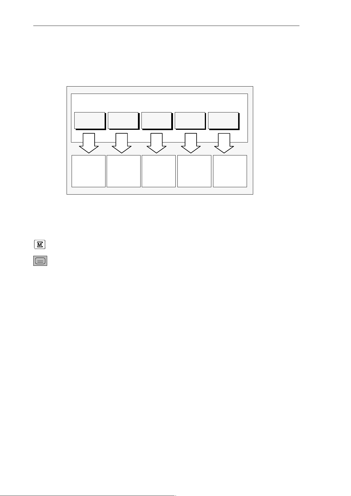
1.2 Operating areas
The basic functions are grouped in the CNC into the following operating areas:
Operating areas
Machine Parameter Program Services
Executing
part programs
Manual
control
Fig. 1-2 SINUMERIK 802S operating areas
Editing program data
Switching between the operating areas
Press the “Machine area” key for direct access to the “Machine” operating area.
Use the area switching key to return from any operating area to the main menu.
Press the area switching key twice to return to the previous operating area.
After turning on the control system, you will always find yourself in the
Machine operating area.
Creating
part programs
Data
import /
export
Diagnosis
Alarm display
Start–up
Protection levels
Sensible points of the control system are password–protected against entering and modifying
data.
However, the operator can alter the classes of protection in the “Machine data display” menu
in the “Diagnosis” operating area.
Default: protection level 3.
In the following menus, entering and modifying data depends on the set protection class:
S tool offsets
S zero offsets
S setting data
S V24 setting
1-14
6FC5 598–3AA10–0BP2 (01.02) (OP–M)
SINUMERIK 802S/802C
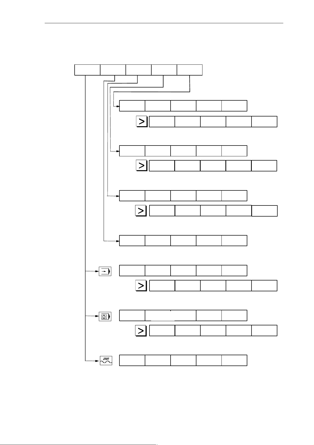
1.3 Overview of the most important softkey functions
1.3 Overview of the most important softkey functions
Introduction
Machine
Parameters Program
Alarms
Data Data
in out
Progr.
Services
Service
display
Display Display
bright. darker
RS232
setting
Execut
f. ext.
Cycles
New Copy
Diagnosis
Start–up
Change
lang.
Error
log
Selection
Delete Rename
Machine
data
Show
Open
Memory
info
R Tool Setting Zero
parameters offset data
Program
control WCS act.val.
Zoom
block
Axis
feed
Block
search
Zoom
block
Axis
feed
Handwheel
Axis
feed
Execut
f. ext.
offset
Act.val. Zoom
Zoom
G funct.
Act.val.
WCS
Zoom
act. val.
Zoom
G funct.
Act.val.
WCS/MCS
Zoom
act.val.
Zoom
M funct.
Zoom
M funct.
SINUMERIK 802S/802C
6FC5 598–3AA10–0BP2 (01.02) (OP–M)
1-15

Introduction
1.4 Pocket calculator
1.4 Pocket calculator
=
3
This function can be activated for all input fields intended for entry of numerical values by means of
the “=” character. To calculate the required value, you can use the four basic arithmetic operations,
and the functions sine, cosine, squaring, as well as the square root function.
If the input field is already loaded with a value, this function writes the value in the input line of
the pocket calculator.
Fig. 1-3 Pocket calculator
Permissible character
The following characters are permitted for input:
+ Value X plus value Y
– Value X minus value Y
* Value X multiplied with value Y
/ Value X divided by value Y
S Sine function
The value X in front of the input cursor is replaced by the value sin(X).
C Cosine function
The value X in front of the input cursor is replaced by the value cos(X).
Q Square function
The value X in front of the input cursor is replaced by the value X
R Square root function
The value X in front of the input cursor is replaced by the value √X.
Calculation examples
100 + (67*3) 100+67*3
sin(45_) 45 S –> 0.707107
cos(45_) 45 C –> 0.707107
2
4
√4 4 R –> 2
The calculation is carried out when the Input key is pressed. The function writes the result to
the input field and automatically closes the pocket calculator.
2.
Task Input
4 Q –> 16
1-16
6FC5 598–3AA10–0BP2 (01.02) (OP–M)
SINUMERIK 802S/802C
Softkeys
Introduction
1.4 Pocket calculator
To calculate auxiliary points on a contour, the pocket calculator provides the following functions:
S calculating the tangential transition between a circle sector and a straight line
S moving a point in a plane
S converting polar coordinates into Cartesian coordinates
S adding the second end point of a contour section ’straight line – straight line’ given via an-
gular interrelation.
These functions are directly linked with the input fields of the programming support. Any values in this input field are written by the pocket calculator into the input line, and the result is
automatically copied into the input fields of the programming support.
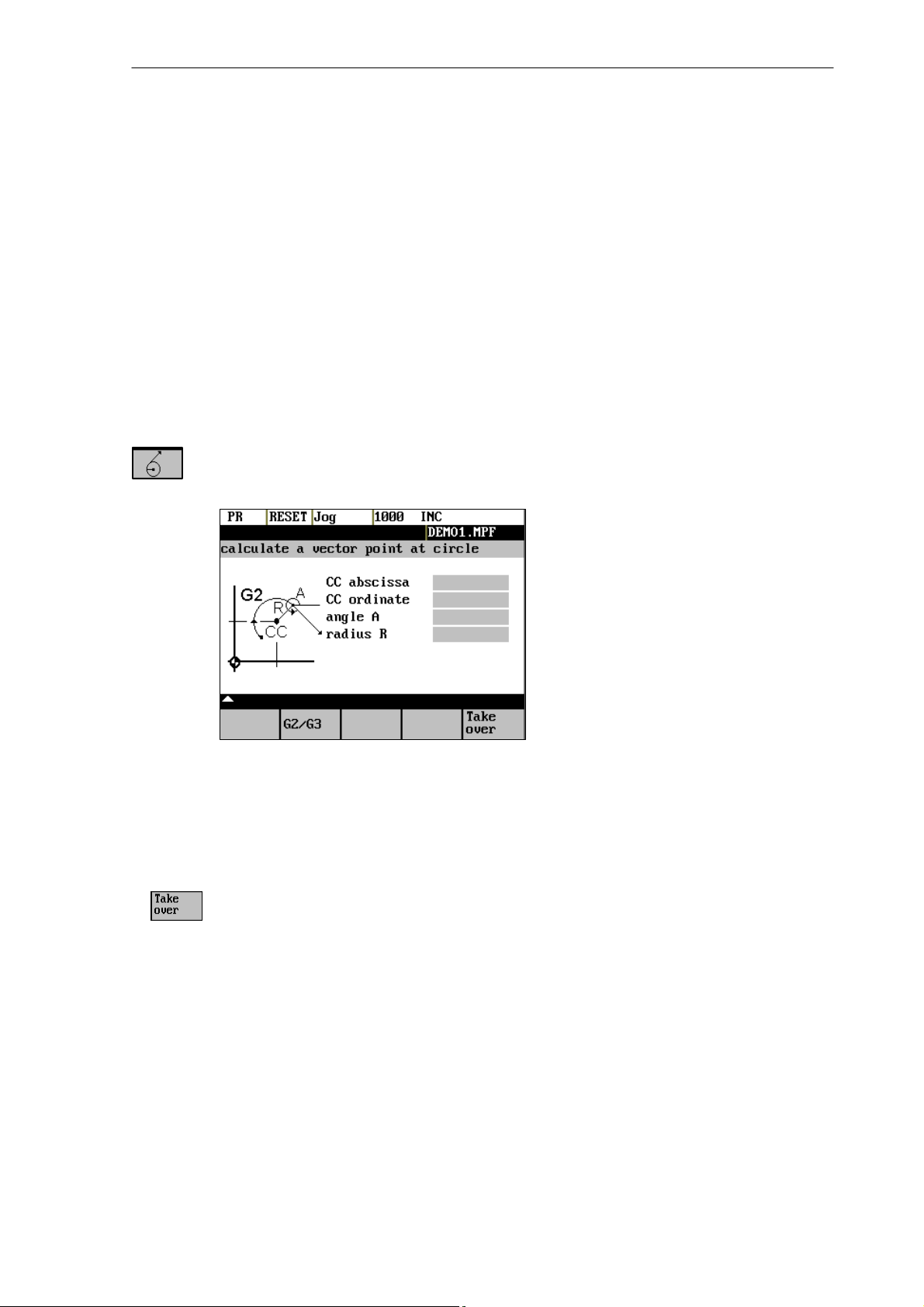
This function is used to calculate a point on a circle. The point results from the angle of the created
tangent and the direction of rotation of the circle.
Fig. 1-4 Calculation of a point on a circle
Enter the circle center, the angle of the tangent and the radius of the circle.
Use the softkeys G2 / G3 to define the direction of rotation of the circle.
The values of abscissa and ordinate are calculated. The abscissa is the first axis of the plane, and
the ordinate the second axis of the plane.
Example
If plane G17 is active, the abscissa is the X axis, and the ordinate the Y axis.
The value of the abscissa is copied into that input field from which the pocket calculator function has been called, and the ordinate value into the next following input field.
SINUMERIK 802S/802C
6FC5 598–3AA10–0BP2 (01.02) (OP–M)
1-17
Introduction
1.4 Pocket calculator
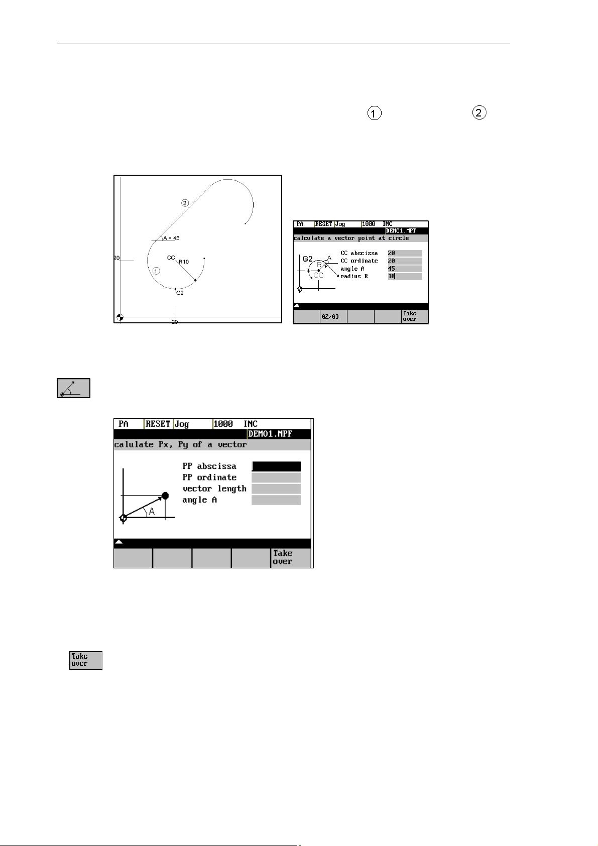
Example
Calculating the intersection point between the circle sector and the straight line .
Given: Radius: 10
Circle center point: X 20 Y20
Ongoing angle of the straight line: 45°
Result: X = 12.928
Y = 27.071
The function calculates the Cartesian coordinates from a straight line specified by length and rise
angle.
Fig. 1-5 Conversion of the polar coordinates into Cartesian coordinates
Enter the pole point (PP) as both an abscissa and ordinate value, the length and the rise angle of the straight line.
1-18
The values of abscissa and ordinate are calculated.
The abscissa value is copied into the input field from which the pocket calculator function has
been called, and the ordinate value into the next following input field.
6FC5 598–3AA10–0BP2 (01.02) (OP–M)
SINUMERIK 802S/802C
Example
Introduction
1.4 Pocket calculator
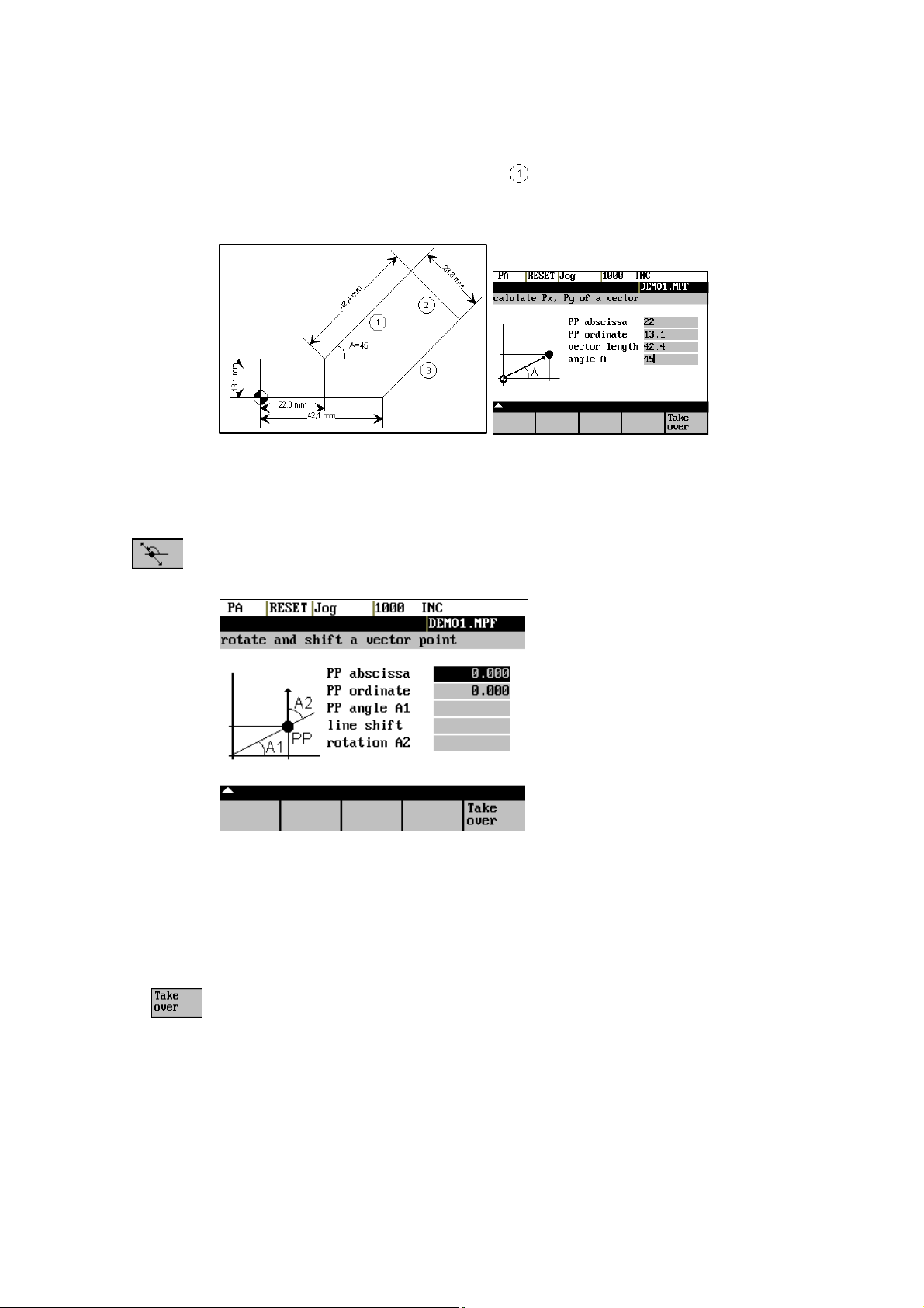
Calculating the end point of the straight line . The straight line is defined by the angle
° uand its length..
A=45
Result: X = 51.981
Y = 43.081
This function can be used to move a point in the plane. The point is on a straight line defined by its
rise angle.
Fig. 1-6 Moving a point in the plane
Enter the rise angle of the straight line and the coordinates of the point.
Enter line shift and rotation of the point with refer to the straight line in the fields “line shift” and
“rotation”.
The values of abscissa and ordinate are calculated.
The pocket calculator copies the abscissa value into the input field from which the pocket calculator function has been called, and the ordinate value into the next following input field.
SINUMERIK 802S/802C
6FC5 598–3AA10–0BP2 (01.02) (OP–M)
1-19
Introduction
1.4 Pocket calculator
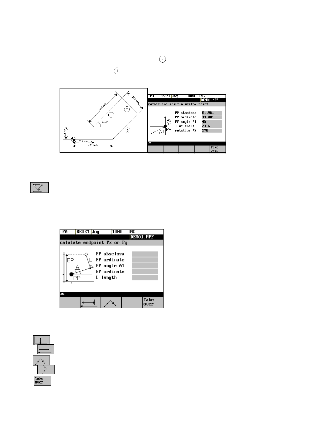
Example
Calculating the end point of the straight line . The straight line stands vertical on the end
point of the straight line (coordinates: X = 51.981, Y = 43.081). The length of the straight
line is also given.
Result: X = 68.668
Y = 26.393
This function calculates the missing end point of the contour section straight line – straight line,
with the second straight line standing vertically on the first straight line.
The following values of the straight line are known:
Straight line 1: Starting point and rise angle
Straight line 2: Length and one end point in the Cartesian coordinate system
Fig. 1-7
1-20
This function chooses the given coordinate of the end position.
The value of ordinate and/or abscissa is given.
The second straight line is rotated in clockwise direction or, with refer to the first straight line, rotated
by 90 degrees in counter–clockwise direction. The function chosses the appropriate setting.
The missing end position is calculated. The value of the abscissa is copied into that input field from
which the pocket calculator function has been called, and the ordinate value into the next following
input field.
6FC5 598–3AA10–0BP2 (01.02) (OP–M)
SINUMERIK 802S/802C
Example
Introduction
1.4 Pocket calculator
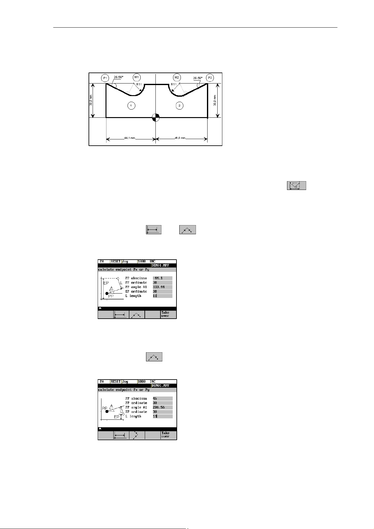
The drawing above must be added by the values of the of the circle center points to be able to
calculate the intersection points between the contour sections. Calculating the missing coordi-
nates of the center points is carried out with the pocket calculator function , since the
radius in the tangential transition stands vertical on the straight line.
Calculating M1 in section 1:
In this section, the radius stands on the straight line section in counter–clockwise direction.
Use the softkeys and to select the given constellation.
Enter the coordinates, the pole point P1, the rise angle of the straight line, the given ordinate value and the circle radius as the length.
Result: X = –19.449
Y = 30
Calculating M2 in section 2:
In this section, the radius stands on the straight line section rotated in clockwise direction.
Use the softkeys to select the given constellation.
Enter the parameters in the screen form.
SINUMERIK 802S/802C
6FC5 598–3AA10–0BP2 (01.02) (OP–M)
Result X = 21.399
Y = 30
1-21
Introduction
1.5 Basic principles
1.5 Basic principles
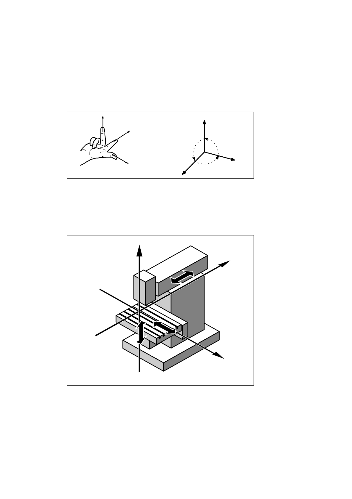
Coordinate sytems
Right–handed, rectangular coordinate systems are used for machine tools.
Such systems describe the movements on the machine as a relative motion between tool and
workpiece.
+Z
Fig. 1-8 Specification of mutual relationship between axis directions;
+X
+Y
+ Z
90°
90°
+Y
90°
+ X
Machine coordinate system (MCS)
The orientation of the coordinate system on the machine tool depends on the particular machine type. It can be turned to various positions.
+Z
+Y
+X
1-22
Fig. 1-9 Example of machine coordinates/axes
The origin of the coordinate system is the machine zero.
All axes are in zero position at this point. This point is merely a reference point determined by
the machine manufacturer. It need not to be approachable.
The traversing range of the machine axes can be negative.
6FC5 598–3AA10–0BP2 (01.02) (OP–M)
SINUMERIK 802S/802C
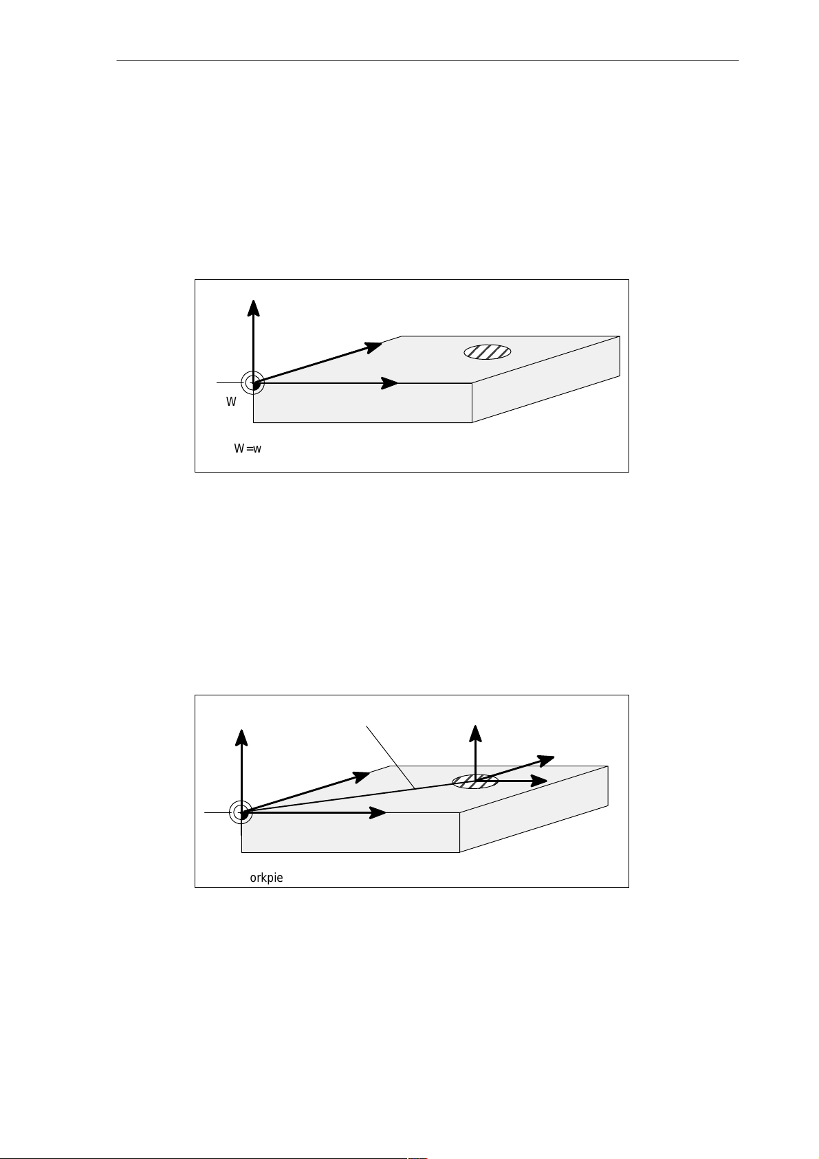
Workpiece coordinate system (WCS)
The workpiece coordinate system described above (see Fig. 1-8) is also used to describe the
geometry of a workpiece in the workpiece program.
The workpiece zero can be freely selected by the programmer. The programmer need not
know the real movement conditions on the machine, i.e. whether the workpiece or the tool
moves; this can be different in the individual axes.
The definition of the directions is based on the assumption that the workpiece does not move
and the tool moves.
Z
Y
Introduction
1.5 Basic principles
W
W=workpiece zero
Fig. 1-10 Workpiece coordinate system
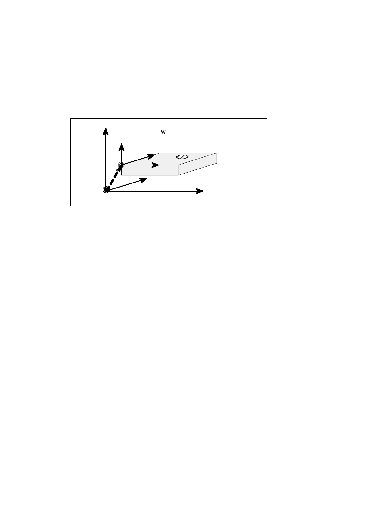
Current workpiece coordinate system
If the programmer feels that it is better to continue his geometrical descriptions from another
zero than the initially selected zero (workpiece zero), he can define a new zero using the programmable zero offset. Reference is always made to the original zero.
The use of the programmable zero offset provides a completely new current workpiece coordinate system. The current workpiece coordinate system can also be turned to the original
workpiece coordinate system (see Section “Programmable Zero Offset and Rotation”).
Programmable offset
Z
Y
X
G158
Z Current
Y
X
W
W=workpiece zero
Fig. 1-11 Coordinates on the workpiece, current workpiece coordinate sy-
stem
SINUMERIK 802S/802C
6FC5 598–3AA10–0BP2 (01.02) (OP–M)
X
1-23
Introduction
1.5 Basic principles
Workpiece clamping
To machine the workpiece, it is clamped on the machine. The workpiece must be aligned such
that the axes of the workpiece coordinate system run in parallel with the machine axes. Any
resultant offset of the machine zero is determined for each axis and entered into the intended
data areas for the settable zero offset. This offset is activated during the NC program execution by means, for example, of a programmable G54 (see Section ”Workpiece Clamping –
Settable Zero Offset ...”).
Z
Machine
Z
Workpiece
W=workpiece zero
M=machine zero
Y
W
z.B.
G54
M
Fig. 1-12 Workpiece on the machine
X
Y
Machine
X
Machine
1-24
6FC5 598–3AA10–0BP2 (01.02) (OP–M)
SINUMERIK 802S/802C
Turning On and Reference Point Approach
Note
Before you switch on the SINUMERIK and the machines, you should also have read the machine documentation, since turning on and reference point approach are machine–dependent
functions.
Operating sequence
First switch on the power supply of the CNC and of the machine. After the control system has
booted, you are in the “Machine” operating area, in the Jog operating mode.
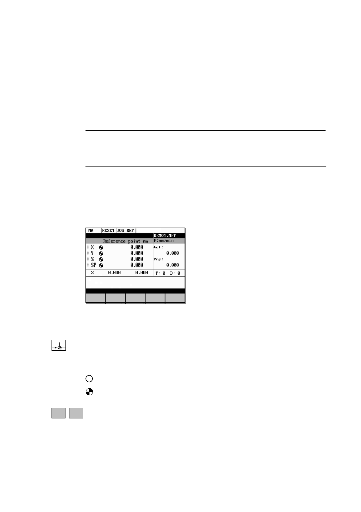
The Reference point approach window is active.
2
+X
Fig. 2-1 Jog Ref basic screen
Reference–point approach can only be executed in the Jog mode.
Activate the “Approach reference point” function by selecting the Ref key on the machine control
panel.
In the “Reference point approach” window (Fig. 2-1), it is displayed whether or not the axes
have to be referenced.
Axis has to be referenced
Axis has reached the reference point
...
Press the direction keys.
-Z
The axis does not move if you select the wrong direction.
Approach the reference point in each axis successively.
SINUMERIK 802S/802C
6FC5 598–3AA10–0BP2 (01.02) (OP–M)
2-25

Turning On and Reference Point Approach
You can quit the function by selecting another operating mode (MDA, Automatic or Jog).
2-26
6FC5 598–3AA10–0BP2 (01.02) (OP–M)
SINUMERIK 802S/802C
Setup
Preliminary remarks
S Before you can use the CNC, set up the machine, tools, etc. on the CNC by:
S entering the tools and tool offsets
S entering/modifying the zero offset
S entering the setting data
3.1 Entering tools and tool offsets
Functionality
The tool offsets consist of several data that describe the geometry, wear and tool type.
Each tool has a defined number of parameters depending on the tool type.
Each tool is identified by its own tool number (T number).
3
See also Section 8.6 “Tool and Tool Offset“.
Operating sequences
Parameter
Tool
Corr.
This function opens the Tool Compensation Data window, which contains the offset values of the
currently active tool. If you select another tool using the <<T or T>> softkeys, the setting remains
when you quit the window.
Fig. 3-1 Tool list
SINUMERIK 802S/802C
6FC5 598–3AA10–0BP2 (01.02) (OP–M)
3-27

Setup
3.2 Creating a new tool
Softkeys
<< D
D >>
<< T
T >>
Search
Reset
edge
New
edge
Delete
tool
New
tool
Select next lower or next higher edge number.
Select next lower or next higher tool.
Pressing this softkey opens the dialog box and the overview of the tool numbers assigned. Enter the
tool number you search for in the input window and start search with OK. If the searched tool exists,
the search function opens the tool offset data box.
Press the ETC key to extend the softkey functions.
All edge compensation values are reset to zero.
Creates a new edge and loads it with the appropriate parameters.
The new edge is created for the currently displayed tool; it is automatically assigned the next
higher edge number (D1 - D9).
Max. 30 edges (in total) can be stored in the memory.
Deletes the tool compensation data of all edges of the selected tool.
Creates new tool compensation data for a new tool.
Note: Max. 20 tools can be created.
Get
Comp.
Determines the length compensation values.
3.2 Creating a new tool
Operating sequence
Press this softkey to create a new tool.
New
tool
Pressing this softkey opens the input window and an overview of the tool numbers assigned.
3-28
6FC5 598–3AA10–0BP2 (01.02) (OP–M)
SINUMERIK 802S/802C
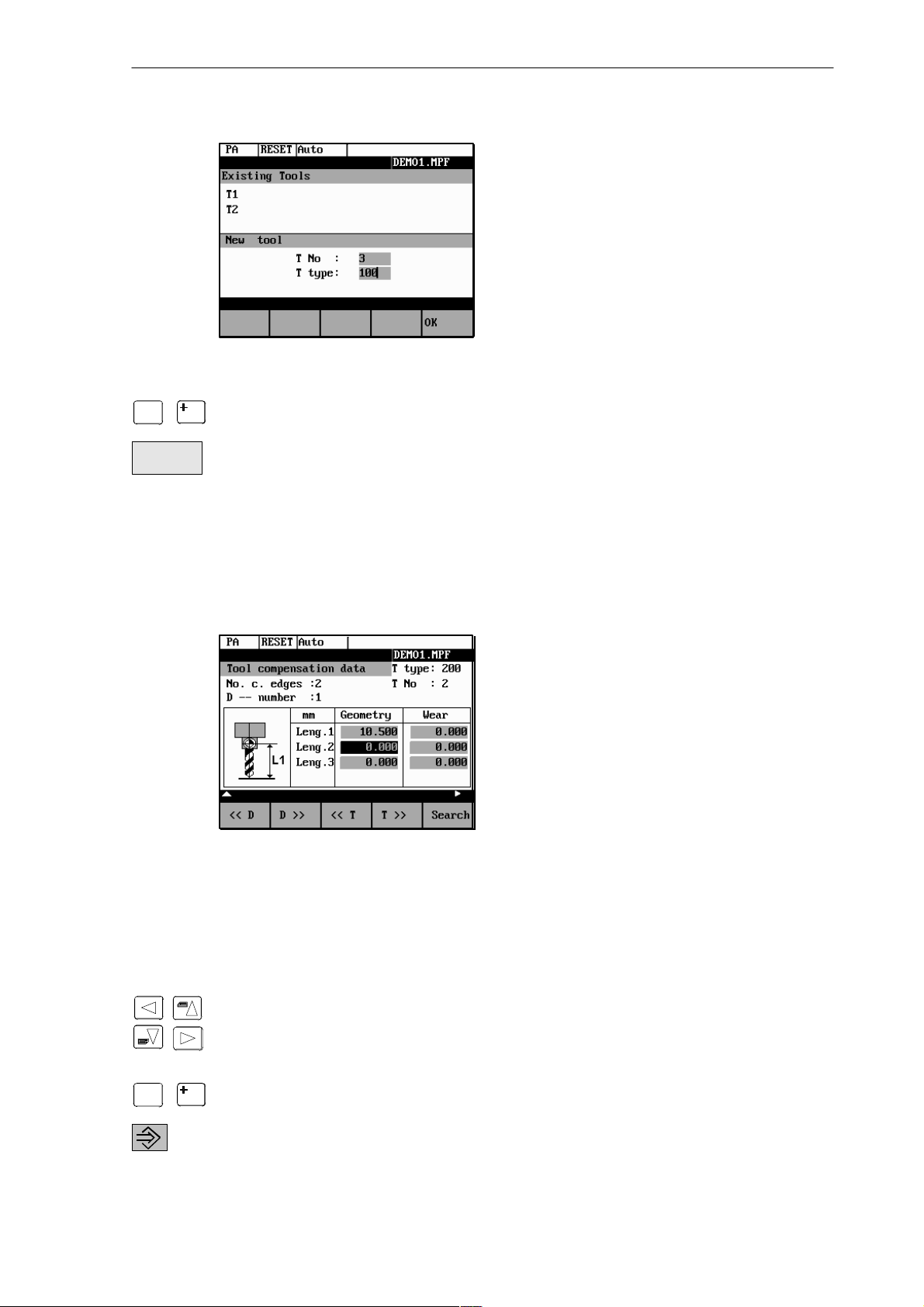
Fig. 3-2 New Tool window
Setup
3.3 Tool compensation data
$
0
. . .
Enter the new T number (in the range from 1 to 32000) and specify the tool type.
9
Press OK to confirm your entry; the Tool Compensation Data window is opened.
OK
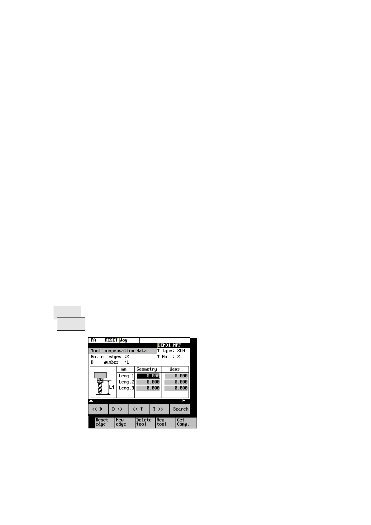
3.3 Tool compensation data
The tool compensation data are divided into length and radius compensation data.
The list is structured according to the tool type.
Fig. 3-3 Tool compensation data
Operating sequence
Enter the offsets by
positioning the cursor on the input field to be modified,
$
0
. . .
entering value(s)
9
and confirming your entry by pressing Input or a cursor selection.
SINUMERIK 802S/802C
6FC5 598–3AA10–0BP2 (01.02) (OP–M)
3-29
Setup
3.4 Determining the tool offsets
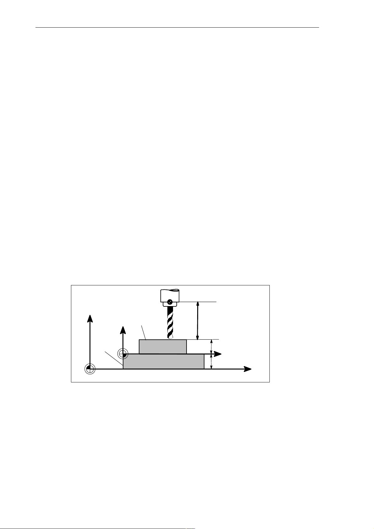
3.4 Determining the tool offsets
Functionality
This function can be used to determine the unknown geometry of a tool T.
Prerequisite
The appropriate tool has been changed. In JOG mode, approach a point on the machine, from
which you knw the machine coordinates, with the edge of the tool. This can be a workpiece
with a knwon position. The machine coordinate value can be split into two components: stored
zero offset and offset.
Procedure
Enter the offset value in the intended Offset field. Then select the required zero offset (e.g.
G54) or G500 if no zero offset is to be calculated. These entries must be made for each selected axis (see Fig. 3–5).
Please note the following: For milling tools, length 1 and the radius must be determined, and
for drilling tools only length 1.
Using the actual position of point F (machine coordinate), the offset entry and the selected
zero offset Gxx (position of the edge), the control system can calculate the assigned compensation value of length 1 or the tool radius.
Note: You can also use a zero offset already determined (e.g. G54 value) as the known machine coordinate. In this case, approach the workpiece zero with the edge of the tool. If the
edge stands directly at the workpiece zero, the offset value is zero.
F–tool carrier reference point
M–machine zero
W–workpiece zero
Z
Machine
Workpiece
M
Fig. 3-4 Determination of length compensation using the example of a drill: length 1/Z
axis
Interm. layer
W
F
Length 1=?
Actual position Z
Known machine
coordinate value Z
Offset
Gxx, z.B. G54
X
Machine
3-30
6FC5 598–3AA10–0BP2 (01.02) (OP–M)
SINUMERIK 802S/802C
 Loading...