


Start-Up 01/2002 Edition
SINUMERIK 802S

SINUMERIK 802S
Start–Up
Valid for |
|
Control |
Software Version |
SINUMERIK 802S |
as from 3 |
01.2002 Edition
Numerical Control System 1
Installing the Control System2
Installing the Drives |
3 |
Start–Up |
4 |
Update |
5 |
Technical Appendix |
6 |
Manual Machine |
7 |
Index

3ls |
SINUMERIK Documentation |
|
Printing history
Brief details of this edition and previous editions are listed below.
IThe status of each edition is shown by the code in the ”Remarks” column.
Status code in the “Remarks” column:
A . . . . . New documentation.
B . . . . . Unrevised reprint with new Order No. C . . . . . Revised edition with new status.
If actual changes have been made on the page since the last edition, this is indicated by a new edition coding in the header on the page.
Edition |
Order–No. |
Remark |
02.99 |
6FC5597-2AA00-0BP2 |
C |
01.02 |
6FC5597-2AA00-0BP2 |
C |
This Manual is included on the documentation on CD–ROM (DOCONCD)
Edition |
Order–No. |
Remark |
11.02 |
6FC5298-6CA00-0BP3 |
C |
Trademarks
SIMATICr, SIMATIC HMIr, SIMATIC NETr, SIROTECr, SINUMERIKr and SIMODRIVEr are registered trademarks of Siemens. Third parties using for their own purposes any other names in this document which refer to trademarks might infringe upon the rights of trademark owners.
This publication was produced with Interleaf V 7
The reproduction, transmission or use of this document or its contents is not permitted without express written authority. Offenders will be liable for demages. All rights, including rights created by patent grant or registration of utility model or design, are reserved.
Siemens AG 2001. All rights reserved.
Other functions not described in this documentation might be executable in the control. This does not, however, represent an obligation to supply such functions with a new control or when servicing.
We have checked that the contents of this document correspond to the hardware and software described. Nonetheless, differences might exist and therefore we cannot guarantee that they are completely identical. The information contained in this document is, however, reviewed regularly and any necessary changes will be included in the next edition. We welcome suggestions for improvement.
Subject to change without prior notice.
Bestell–Nr. 6FC5597-2AA00-0BP2 |
Siemens–Aktiengesellschaft |
Printed in the Federal Republic of Germany |
|

Safety notices
This Manual contains notices intended to ensure your personal safety and to avoid material damage. The notices are highlighted by a warning triangle and, depending on the degree of hazard, represented as shown below:
Danger
!indicates that loss of life, severe personal injury or substantial material damage will result if the appropriate precautions are not taken.
Warning
!indicates that loss of life, severe personal injury or substantial material damage may result if the appropriate precautions are not taken.
Caution
!indicates that minor personal injury or material damage may result if the appropriate precautions are not taken.
Caution
without a warning triangle means that a material damage can occur if the appropriate precautions are not taken.
Attention
means that an undesirede event or status can occur if the appropriate note is not observed.
Note
is used to draw your special attention to an important information on the product, the handling of the product or the corresponding part of the documentation.
Qualified personnel
Start–up and operation of a device may only be carried out by qualified personnel. Qualified personnel as referred to in the safety notices provided in this Manual are persons who are authorized to start up, ground and tag devices, systems and circuits according to the relevant safety standards.
Usage as per intended purpose
Please observe the following:
Warning
!The device may only be used for the cases of application, as intended by the Catalog, and only in conjunction with third–party devices and components recommended or approved by Siemens.
The proper and safe operation of the product requires transport, storage and installation according to the relevant instructions and qualified operation and maintenance at the prescribed intervals.
SINUMERIK 802S |
v |
6FC5 597–2AA00–0BP2 (01.02) |

Table of Contents
Table of Contents
1 |
SINUMERIK 802S Control System . . . . . . . . . . . . . . . . . . . . . . . . . . . . . . . . . . . . . . . . . . . . . . |
1-9 |
|
|
1.1 |
Components of the SINUMERIK 802S . . . . . . . . . . . . . . . . . . . . . . . . . . . . . . . . . . . . . . . . . . . |
1-9 |
|
1.2 |
Technical data . . . . . . . . . . . . . . . . . . . . . . . . . . . . . . . . . . . . . . . . . . . . . . . . . . . . . . . . . . . . . . . . |
1-13 |
2 |
Installing the Control System . . . . . . . . . . . . . . . . . . . . . . . . . . . . . . . . . . . . . . . . . . . . . . . . . . |
2-15 |
|
|
2.1 |
Installing and removing the SINUMERIK 802S . . . . . . . . . . . . . . . . . . . . . . . . . . . . . . . . . . . . |
2-15 |
|
2.2 |
Interfaces and cables . . . . . . . . . . . . . . . . . . . . . . . . . . . . . . . . . . . . . . . . . . . . . . . . . . . . . . . . . . |
2-18 |
|
2.3 |
Connecting the individual components . . . . . . . . . . . . . . . . . . . . . . . . . . . . . . . . . . . . . . . . . . . |
2-21 |
|
2.3.1 |
Connecting the operator panel . . . . . . . . . . . . . . . . . . . . . . . . . . . . . . . . . . . . . . . . . . . . . . . . . . |
2-21 |
|
2.3.2 |
Connecting the feed drives . . . . . . . . . . . . . . . . . . . . . . . . . . . . . . . . . . . . . . . . . . . . . . . . . . . . . |
2-23 |
|
2.3.3 |
Connecting the spindle drive (X3) . . . . . . . . . . . . . . . . . . . . . . . . . . . . . . . . . . . . . . . . . . . . . . . |
2-25 |
|
2.3.4 |
Connecting the spindle measuring system (X4) . . . . . . . . . . . . . . . . . . . . . . . . . . . . . . . . . . . . |
2-27 |
|
2.3.5 |
Configuration of the RS232 interface connection (X8) . . . . . . . . . . . . . . . . . . . . . . . . . . . . . . |
2-29 |
|
2.3.6 |
Connecting handwheels (X10) . . . . . . . . . . . . . . . . . . . . . . . . . . . . . . . . . . . . . . . . . . . . . . . . . . |
2-30 |
|
2.3.7 |
Connecting NCREADY (X20) . . . . . . . . . . . . . . . . . . . . . . . . . . . . . . . . . . . . . . . . . . . . . . . . . . . |
2-31 |
|
2.3.8 |
Connecting the digital inputs and outputs (X2003 ... X2006) . . . . . . . . . . . . . . . . . . . . . . . . . |
2-34 |
|
2.4 |
ENC and operator panel power supply (X1) . . . . . . . . . . . . . . . . . . . . . . . . . . . . . . . . . . . . . . . |
2-37 |
|
2.5 |
Grounding . . . . . . . . . . . . . . . . . . . . . . . . . . . . . . . . . . . . . . . . . . . . . . . . . . . . . . . . . . . . . . . . . . . |
2-38 |
|
2.6 |
LEDs and operating elements on the ENC unit . . . . . . . . . . . . . . . . . . . . . . . . . . . . . . . . . . . . |
2-40 |
3 |
Installing the STEPDRIVE C Drives . . . . . . . . . . . . . . . . . . . . . . . . . . . . . . . . . . . . . . . . . . . . |
3-41 |
|
|
3.1 |
Installing and removing the STEPDRIVE C drive modules . . . . . . . . . . . . . . . . . . . . . . . . . . . |
3-41 |
|
3.2 |
Cabling . . . . . . . . . . . . . . . . . . . . . . . . . . . . . . . . . . . . . . . . . . . . . . . . . . . . . . . . . . . . . . . . . . . . . . |
3-43 |
|
3.3 |
Starting up the drive modules . . . . . . . . . . . . . . . . . . . . . . . . . . . . . . . . . . . . . . . . . . . . . . . . . . . |
3-45 |
|
3.4 |
Error messages and error elimination . . . . . . . . . . . . . . . . . . . . . . . . . . . . . . . . . . . . . . . . . . . . |
3-46 |
4 |
Start-Up |
. . . . . . . . . . . . . . . . . . . . . . . . . . . . . . . . . . . . . . . . . . . . . . . . . . . . . . . . . . . . . . . . . . . . . . |
4-47 |
|
4.1 |
General . . . . . . . . . . . . . . . . . . . . . . . . . . . . . . . . . . . . . . . . . . . . . . . . . . . . . . . . . . . . . . . . . . . . . . |
4-47 |
|
4.1.1 |
Access levels . . . . . . . . . . . . . . . . . . . . . . . . . . . . . . . . . . . . . . . . . . . . . . . . . . . . . . . . . . . . . . . . . |
4-48 |
|
4.1.2 |
Structure of machine data (MD) and setting data (SD) . . . . . . . . . . . . . . . . . . . . . . . . . . . . . . |
4-49 |
|
4.1.3 |
Handling machine data . . . . . . . . . . . . . . . . . . . . . . . . . . . . . . . . . . . . . . . . . . . . . . . . . . . . . . . . |
4-51 |
|
4.1.4 |
Data saving . . . . . . . . . . . . . . . . . . . . . . . . . . . . . . . . . . . . . . . . . . . . . . . . . . . . . . . . . . . . . . . . . . |
4-51 |
|
4.2 |
Turning on and booting the control system . . . . . . . . . . . . . . . . . . . . . . . . . . . . . . . . . . . . . . . . |
4-53 |
|
4.2.1 |
Boot messages . . . . . . . . . . . . . . . . . . . . . . . . . . . . . . . . . . . . . . . . . . . . . . . . . . . . . . . . . . . . . . . |
4-55 |
|
4.3 |
Starting up the PLC . . . . . . . . . . . . . . . . . . . . . . . . . . . . . . . . . . . . . . . . . . . . . . . . . . . . . . . . . . . |
4-57 |
|
4.3.1 |
Commissioning of the PLC . . . . . . . . . . . . . . . . . . . . . . . . . . . . . . . . . . . . . . . . . . . . . . . . . . . . . |
4-57 |
|
4.3.2 |
Start–up modes of the PLC . . . . . . . . . . . . . . . . . . . . . . . . . . . . . . . . . . . . . . . . . . . . . . . . . . . . . |
4-58 |
|
4.3.3 |
PLC alarms . . . . . . . . . . . . . . . . . . . . . . . . . . . . . . . . . . . . . . . . . . . . . . . . . . . . . . . . . . . . . . . . . . |
4-60 |
|
4.3.4 |
Machine control panel (MCP) layout . . . . . . . . . . . . . . . . . . . . . . . . . . . . . . . . . . . . . . . . . . . . . |
4-65 |
|
4.3.5 |
PLC programming . . . . . . . . . . . . . . . . . . . . . . . . . . . . . . . . . . . . . . . . . . . . . . . . . . . . . . . . . . . . . |
4-66 |
|
4.3.6 |
Instruction set . . . . . . . . . . . . . . . . . . . . . . . . . . . . . . . . . . . . . . . . . . . . . . . . . . . . . . . . . . . . . . . . |
4-70 |
|
4.3.7 |
Programm organization . . . . . . . . . . . . . . . . . . . . . . . . . . . . . . . . . . . . . . . . . . . . . . . . . . . . . . . . |
4-77 |
|
4.3.8 |
Data organization . . . . . . . . . . . . . . . . . . . . . . . . . . . . . . . . . . . . . . . . . . . . . . . . . . . . . . . . . . . . . |
4-78 |
|
4.3.9 |
Interface to the control system . . . . . . . . . . . . . . . . . . . . . . . . . . . . . . . . . . . . . . . . . . . . . . . . . . |
4-78 |
|
4.3.10 |
Testing and monitoring the user program . . . . . . . . . . . . . . . . . . . . . . . . . . . . . . . . . . . . . . . . . |
4-78 |
|
4.4 |
PLC applications “Download/Upload/Copy/Compare” . . . . . . . . . . . . . . . . . . . . . . . . . . . . . . . |
4-79 |
|
4.5 |
User Interface . . . . . . . . . . . . . . . . . . . . . . . . . . . . . . . . . . . . . . . . . . . . . . . . . . . . . . . . . . . . . . . . |
4-80 |
|
4.6 |
Technology Setting . . . . . . . . . . . . . . . . . . . . . . . . . . . . . . . . . . . . . . . . . . . . . . . . . . . . . . . . . . . . |
4-81 |
|
4.7 |
Commissioning . . . . . . . . . . . . . . . . . . . . . . . . . . . . . . . . . . . . . . . . . . . . . . . . . . . . . . . . . . . . . . . |
4-82 |
vi |
SINUMERIK 802S |
6FC5 597–2AA00–0BP2 (01.02) |

Table of Contents
|
4.7.1 |
Entering the general machine data . . . . . . . . . . . . . . . . . . . . . . . . . . . . . . . . . . . . . . . . . . . . . . |
4-82 |
|
4.7.2 |
Starting up the axes . . . . . . . . . . . . . . . . . . . . . . . . . . . . . . . . . . . . . . . . . . . . . . . . . . . . . . . . . . . |
4-84 |
|
4.7.3 |
Starting up the spindle . . . . . . . . . . . . . . . . . . . . . . . . . . . . . . . . . . . . . . . . . . . . . . . . . . . . . . . . . |
4-94 |
|
4.7.4 |
Completing the start–up . . . . . . . . . . . . . . . . . . . . . . . . . . . . . . . . . . . . . . . . . . . . . . . . . . . . . . . . |
4-101 |
|
4.7.5 |
Starting up the cycles . . . . . . . . . . . . . . . . . . . . . . . . . . . . . . . . . . . . . . . . . . . . . . . . . . . . . . . . . . |
4-101 |
|
4.8 |
Series machine start-up . . . . . . . . . . . . . . . . . . . . . . . . . . . . . . . . . . . . . . . . . . . . . . . . . . . . . . . . |
4-102 |
5 |
Software Update . . . . . . . . . . . . . . . . . . . . . . . . . . . . . . . . . . . . . . . . . . . . . . . . . . . . . . . . . . . . . . |
5-105 |
|
|
5.1 |
Updating the system software using a PC/PG . . . . . . . . . . . . . . . . . . . . . . . . . . . . . . . . . . . . . |
5-105 |
|
5.2 |
Updating the system software incl. user data without using a PC/PG . . . . . . . . . . . . . . . . . . |
5-107 |
|
5.3 |
Update errors . . . . . . . . . . . . . . . . . . . . . . . . . . . . . . . . . . . . . . . . . . . . . . . . . . . . . . . . . . . . . . . . . |
5-108 |
6 |
Technical Appendix . . . . . . . . . . . . . . . . . . . . . . . . . . . . . . . . . . . . . . . . . . . . . . . . . . . . . . . . . . . |
6-109 |
|
|
6.1 |
List of machine and setting data . . . . . . . . . . . . . . . . . . . . . . . . . . . . . . . . . . . . . . . . . . . . . . . . . |
6-109 |
|
6.1.1 |
Display machine data . . . . . . . . . . . . . . . . . . . . . . . . . . . . . . . . . . . . . . . . . . . . . . . . . . . . . . . . . . |
6-109 |
|
6.1.2 |
General machine data . . . . . . . . . . . . . . . . . . . . . . . . . . . . . . . . . . . . . . . . . . . . . . . . . . . . . . . . . |
6-110 |
|
6.1.3 |
Channel-Specific Machine Data . . . . . . . . . . . . . . . . . . . . . . . . . . . . . . . . . . . . . . . . . . . . . . . . . |
6-111 |
|
6.1.4 |
Axis-specific machine data . . . . . . . . . . . . . . . . . . . . . . . . . . . . . . . . . . . . . . . . . . . . . . . . . . . . . |
6-112 |
|
6.1.5 |
Setting data . . . . . . . . . . . . . . . . . . . . . . . . . . . . . . . . . . . . . . . . . . . . . . . . . . . . . . . . . . . . . . . . . . |
6-119 |
|
6.2 |
PLC user interface signals . . . . . . . . . . . . . . . . . . . . . . . . . . . . . . . . . . . . . . . . . . . . . . . . . . . . . . |
6-120 |
|
6.2.1 |
Address ranges . . . . . . . . . . . . . . . . . . . . . . . . . . . . . . . . . . . . . . . . . . . . . . . . . . . . . . . . . . . . . . . |
6-120 |
|
6.2.2 |
Retentive data area . . . . . . . . . . . . . . . . . . . . . . . . . . . . . . . . . . . . . . . . . . . . . . . . . . . . . . . . . . . |
6-121 |
|
6.2.3 |
NCK signals . . . . . . . . . . . . . . . . . . . . . . . . . . . . . . . . . . . . . . . . . . . . . . . . . . . . . . . . . . . . . . . . . . |
6-122 |
|
6.2.4 |
Channel signals . . . . . . . . . . . . . . . . . . . . . . . . . . . . . . . . . . . . . . . . . . . . . . . . . . . . . . . . . . . . . . |
6-124 |
|
6.2.5 |
Axis/spindle signals . . . . . . . . . . . . . . . . . . . . . . . . . . . . . . . . . . . . . . . . . . . . . . . . . . . . . . . . . . . |
6-131 |
|
6.2.6 |
Signals from/to MMC . . . . . . . . . . . . . . . . . . . . . . . . . . . . . . . . . . . . . . . . . . . . . . . . . . . . . . . . . . |
6-135 |
|
6.2.7 |
Machine control panel signals (MCP signals) . . . . . . . . . . . . . . . . . . . . . . . . . . . . . . . . . . . . . . |
6-137 |
|
6.2.8 |
PLC machine data . . . . . . . . . . . . . . . . . . . . . . . . . . . . . . . . . . . . . . . . . . . . . . . . . . . . . . . . . . . . |
6-138 |
|
6.2.9 |
User alarm . . . . . . . . . . . . . . . . . . . . . . . . . . . . . . . . . . . . . . . . . . . . . . . . . . . . . . . . . . . . . . . . . . . |
6-140 |
|
6.3 |
PLC user program for turning (UPGMTURN) . . . . . . . . . . . . . . . . . . . . . . . . . . . . . . . . . . . . . . |
6-142 |
|
6.3.1 |
Function . . . . . . . . . . . . . . . . . . . . . . . . . . . . . . . . . . . . . . . . . . . . . . . . . . . . . . . . . . . . . . . . . . . . . |
6-142 |
|
6.3.2 |
PLC machine data . . . . . . . . . . . . . . . . . . . . . . . . . . . . . . . . . . . . . . . . . . . . . . . . . . . . . . . . . . . . |
6-143 |
|
6.3.3 |
Input/output configuration . . . . . . . . . . . . . . . . . . . . . . . . . . . . . . . . . . . . . . . . . . . . . . . . . . . . . . |
6-145 |
|
6.3.4 |
Description of the logics . . . . . . . . . . . . . . . . . . . . . . . . . . . . . . . . . . . . . . . . . . . . . . . . . . . . . . . . |
6-149 |
|
6.3.5 |
UPGMTURN program structure . . . . . . . . . . . . . . . . . . . . . . . . . . . . . . . . . . . . . . . . . . . . . . . . . |
6-153 |
|
6.4 |
Application note: Unipolar spindle control . . . . . . . . . . . . . . . . . . . . . . . . . . . . . . . . . . . . . . . . . |
6-156 |
7 |
Manual Machine . . . . . . . . . . . . . . . . . . . . . . . . . . . . . . . . . . . . . . . . . . . . . . . . . . . . . . . . . . . . . . |
7-157 |
|
|
7.1 |
Hardware and software requirements for the installation . . . . . . . . . . . . . . . . . . . . . . . . . . . . |
7-157 |
|
7.2 |
Loading the software . . . . . . . . . . . . . . . . . . . . . . . . . . . . . . . . . . . . . . . . . . . . . . . . . . . . . . . . . . |
7-158 |
|
7.3 |
Switching the user interface . . . . . . . . . . . . . . . . . . . . . . . . . . . . . . . . . . . . . . . . . . . . . . . . . . . . |
7-160 |
|
7.4 |
Switching the language . . . . . . . . . . . . . . . . . . . . . . . . . . . . . . . . . . . . . . . . . . . . . . . . . . . . . . . . |
7-160 |
|
7.5 |
Additional machine data . . . . . . . . . . . . . . . . . . . . . . . . . . . . . . . . . . . . . . . . . . . . . . . . . . . . . . . . |
7-161 |
|
7.6 |
Input limitations with regard to the user interface . . . . . . . . . . . . . . . . . . . . . . . . . . . . . . . . . . . |
7-161 |
|
7.7 |
Operation without machine control panel (MCP) . . . . . . . . . . . . . . . . . . . . . . . . . . . . . . . . . . . |
7-162 |
|
7.8 |
I/O assignment in the standard PLC program . . . . . . . . . . . . . . . . . . . . . . . . . . . . . . . . . . . . . . |
7-162 |
|
7.8.1 |
Assignment of the digital inputs: . . . . . . . . . . . . . . . . . . . . . . . . . . . . . . . . . . . . . . . . . . . . . . . . . |
7-162 |
|
7.8.2 |
Assignment of the digital outputs: . . . . . . . . . . . . . . . . . . . . . . . . . . . . . . . . . . . . . . . . . . . . . . . . |
7-164 |
|
7.9 |
Default assignment of special data for the “Manual machine” . . . . . . . . . . . . . . . . . . . . . . . . |
7-165 |
SINUMERIK 802S |
vii |
6FC5 597–2AA00–0BP2 (01.02) |

Table of Contents
notice
viii |
SINUMERIK 802S |
6FC5 597–2AA00–0BP2 (01.02) |
SINUMERIK 802S Control System |
1 |
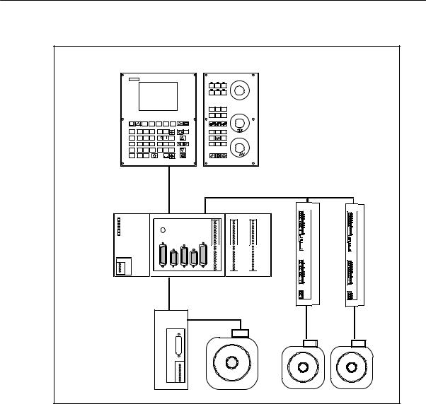
1.1Components of the SINUMERIK 802S
What is SINUMERIK?
The SINUMERIK 802S is a microprocessor–controlled numerical control system for simple machine tools with stepper motor drives (”S” = stepper).
Hardware components
It consists of the following hardware components:
SENC: Control component for a maximum of 3 stepper motor axes and an analog interface for a main spindle drive (ENC = Economical Numerical Control)
SOP020: NC operator panel with graphics display and keyboard
SMCP: machine control panel
SDI/O16: 16 binary inputs/outputs each extendable to max. 64 by using 4 modules
SINUMERIK 802S |
1-9 |
6FC5 597–2AA00–0BP2 (01.02) |
SINUMERIK 802S Control System
1.1Components of the SINUMERIK 802S
OP020 MCP
|
|
|
|
|
|
|
|
|
|
INC JOG |
REF |
|
|
|
|
|
|
|
|
|
|
AUTO SBL |
MDA |
M |
|
|
|
|
|
|
|
|
|
|
|
N |
X |
|
Y |
Z |
|
T |
D |
|
VM |
+X |
% |
|
|
|
|
||||||||
G E |
7 |
> |
8 |
9 |
+ |
|
|
K |
Pg |
-Z |
+Z |
F O |
4 |
< |
5 |
6 |
|
LA _ |
P |
R |
|
-X |
|
S Q |
1 |
|
2 |
3 = |
AF U B V |
C W |
Pg |
|
|
||
M H |
|
|
0 |
$ |
|
|
INS |
|
|
|
% |
|
|
|
|
|
|
|
|
PULSE |
|
|
|
|
|
|
X10 |
X2003 |
X2005 |
|
|
|
|
|
|
MPG |
IN |
OUT |
ERR |
|
|
|
|
|
|
|
L+ |
POK |
|
|
|
|
|
|
0 |
0 |
|
|
|
|
|
|
1 |
1 |
|
DIAG |
|
|
|
|
|
|
2 |
2 |
|
|
|
|
|
|
|
3 |
3 |
|
|
|
|
|
|
|
4 |
4 |
|
|
|
|
|
|
|
5 |
5 |
|
|
|
|
|
|
|
6 |
6 |
|
|
|
|
|
|
|
7 |
7 |
|
|
|
|
|
|
|
M |
M |
|
|
|
|
|
|
|
|
L+ |
|
|
|
|
|
|
|
8 |
8 |
|
|
|
|
|
|
|
9 |
9 |
|
|
|
|
|
|
|
10 |
10 |
DC24V X1 |
|
|
|
|
|
|
11 |
11 |
|
|
|
|
|
|
|
12 |
12 |
|
|
|
|
|
|
|
13 |
13 |
L+ |
|
|
|
|
|
|
14 |
14 |
M |
|
|
|
|
|
|
15 |
15 |
L+ |
|
|
|
|
|
|
M |
M |
M |
AXIS |
SPINDLE |
ECUODER |
RS232 |
OPI |
DI |
|
|
|
X2 |
X3 |
X4 |
X8 |
X9 |
X20 |
X2004 |
X2006 |
ECU |
|
|
|
|
|
|
DI/O |
|
|
|
|
|
External spindle |
|
|||
|
|
|
|
drive |
|
|
DRIVEs |
|
|
|
|
|
|
|
|
|
|
|
|
|
|
|
|
|
|
Stepper |
|
|
|
|
|
|
|
|
motors |
Fig. 1-1 SINUMERIK 802S hardware components (turning variant)
1-10 |
SINUMERIK 802S |
6FC5 597–2AA00–0BP2 (01.02) |
SINUMERIK 802S Control System
1.1 Components of the SINUMERIK 802S
Software components
The SINUMERIK 802S comprises the following software components, which can be ordered:
SSystem software on the permanent FLASH memory of the ENC
–Boot software,
loads the remaining system software from the permanent memory into the user memory (DRAM) and starts the system.
–MMC software (Man Machine Communication), implements all operating functions
–NCK software (NC Kernel)
implements all NC functions. This software controls an NC channel with a maximum of 3 movement axes and a spindle.
–PLC software (Programmable Logic Control), executes the Integrated PLC user program cyclically.
–Integrated PLC user program
intended to adjust the SINUMERIK 802S to the machine functions (see also Description of Functions “Integrated User Program for SINUMERIK 802S”).
SToolbox
–WinPCIN transfer program for a PC/PG (programming device) to transfer user data and programs
–Text manager
–Cycle kit for loading into the control system using WinPCIN
–User program library
–Technological machine data files
–Programming tool
SUpdate diskettes
–Update program with operator prompting system
–802S system software, packed, for loading and programming the SINUMERIK 802S via an update program.
User data
User data are:
SMachine data
SSetting data
STool data
SR parameters
SZero offsets
SCompensation data
SPart programs
SStandard cycles
Data saving Modified user data are saved for at least 50 h after power off or power failure. After then, they might get lost.
SINUMERIK 802S |
1-11 |
6FC5 597–2AA00–0BP2 (01.02) |
SINUMERIK 802S Control System
1.1Components of the SINUMERIK 802S
Warning
!To avoid data loss, the operator must carry out data saving (see Section 4.1.4).
1-12 |
SINUMERIK 802S |
6FC5 597–2AA00–0BP2 (01.02) |

SINUMERIK 802S Control System
1.2 Technical data
1.2Technical data
Connected load
Table 1-1 |
Connected load |
|
|
|
|
|
|
|
|
|
|
|
|
|
|
|
|
|
Parameter |
Min. |
|
Typ. |
Max. |
Unit |
|
|
|
|
|
|
|
|
|
|
|
Supply voltage |
20.4 |
|
|
28.8 |
V |
|
|
|
|
|
|
|
|
|
|
|
|
Ripple |
|
|
|
|
3.6 |
Vss |
|
|
|
|
|
|
|
|
|
||
Current consumption from 24 V |
|
1 |
|
A |
|
* |
||
|
|
|
|
|
|
|
||
Power dissipation of ENC |
|
15 |
|
W |
|
|
||
Power dissipation of OP020 |
|
7 |
|
W |
|
|
||
Power dissipation of MCP |
|
- |
|
|
|
|
||
Power dissipation of DI/O16 |
|
7 |
|
W |
|
** |
||
|
|
|
|
|
|
|
|
|
Start–up current |
|
|
|
2.6 |
A |
|
|
|
|
|
|
|
|
|
|
|
|
* |
Basic configuration of ENC, |
|
|
further DI/O16 |
connected |
|||
|
OP020, MCP and DI/O16, all |
|
|
will increase by 0.05 A each. |
||||
|
outputs open, |
** |
at nominal load |
|
|
|||
|
current consumption for any |
|
|
|
|
|
|
|
Weight
Table 1-2 |
Weight |
|
|
|
|
|
Component |
Weight [g] |
|
|
|
ENC component |
900 g |
|
|
|
|
DI/O16 component |
350 g |
|
|
|
|
OP020 component |
1,800 g |
|
|
|
|
MCP component |
1,200 g |
|
|
|
|
Dimensions
Table 1-3 |
Component dimensions |
|
|
|
|
|
Component |
Dimensions HxWxD [mm] |
|
|
|
ENC component |
125 x 200 x 118 |
|
|
|
|
DI/O component |
125 x 80 x 118 |
|
|
|
|
OP020 component |
300 x 250 x 50 |
|
|
|
|
MCP component |
300 x 170 x 50 |
|
|
|
|
SINUMERIK 802S |
1-13 |
6FC5 597–2AA00–0BP2 (01.02) |

SINUMERIK 802S Control System
1.2Technical data
Environmental operating conditions
Table 1-4 |
Environmental operating conditions |
|
|
|
|
|
Parameter |
|
|
|
|
Temperature range |
0...55 °C |
|
|
|
|
Permissible relative humidity |
5...95 % without condensation |
|
|
|
|
Air pressure |
|
700...1,060 hPa |
|
|
|
The operating conditions comply with IEC 1131-2.
Installation in a housing (e.g. cubicle) is absolutely necessary for operation.
Transport and storage conditions
Table 1-5 |
Transport and storage conditions |
|
|
|
|
|
Parameter |
|
|
|
|
Temperature range |
Transport: -40...70 °C |
|
|
|
Storage: –20 ... 55 °C |
|
|
|
Permissible relative air humidity |
5...95 % without condensation |
|
|
|
|
Air pressure |
|
700...1,060 hPa |
|
|
|
Transport height |
-1,000...3,000 m |
|
|
|
|
Free fall in transport package |
v 1,200 mm |
|
|
|
|
Protective quality and degree of protection
Class of protection I to IEC 536.
No PE terminal required.
Foreign matter and water protection to IEC 529.
Sfor ENC and DI/O16: IP 20
Sfor OP020 and MCP: IP 54 front
IP 00 rear
1-14 |
SINUMERIK 802S |
6FC5 597–2AA00–0BP2 (01.02) |

Installing the Control System |
2 |
2.1Installing and removing the SINUMERIK 802S
Warning
!Before performing any installation work, always first make sure that the system is disconnected from the mains!
The modules contain electrostatically sensitive devices.
It must be ensured that persons without ESD protection never touch printed circuit boards or components when handling operator and machine control panels.
Approach
Prior to installation, the machine control panel can be provided with a spindle override switch and an emergency stop button. If these are not required, the openings must be covered with the supplied self–adhesive covers.
1.Mount the spindle override switch.
2.Install the operator panel and the machine control panel.
3.Connect the panel using ribbon cable.
4.Install the DIN rail.
5.Connect the ENC and DI/O components.
Note
If you want to connect several DI/O16 components, it may be necessary to remove the right– hand connector from the housing.
6. Slide the components onto the DIN rail, tilt it down and screw it tight.
Removing the control system
The control components are removed as described above in the reverse order.
SINUMERIK 802S |
2-15 |
6FC5 597–2AA00–0BP2 (01.02) |

Installing the Control System
2.1 Installing and removing the SINUMERIK 802S
Warning
!Before removing the control components, always first make sure that the system is disconnected from the mains!
2-16 |
SINUMERIK 802S |
6FC5 597–2AA00–0BP2 (01.02) |

Installing the Control System
2.1Installing and removing the SINUMERIK 802S
Mounting dimensions
The dimensions shown below are important for installing the control components:
8 |
|
|
250 |
|
|
|
|
|
170 |
|
|
|
|
|
|
|
|
|
|
|
|
142 |
|
|
|
|
|
|
|
|
|
|
|
|
|
|
|
|
|
|
|
|
300 |
|
|
|
|
|
|
|
|
|
|
SubD |
142 |
|
|
A |
|
|
|
|
|
|
|
|
|
|
F |
|
|
|
|
|
|
|
|
8 |
|
234 |
|
|
|
|
154 |
45 |
|
|
|
|
|
|
|
8 |
||||
|
|
|
|
|
|
|
|
|
|
80 |
|
Mounting |
4,8 |
|
|
|
|
|
|
|
|
|
|
|
|
|
|
|
|
482 |
40 |
|
|
|
|
|
|
|
|
|
|
120 |
|
|
|
|
|
|
|
|
|
|
|
|
32,5 |
|
|
ENCODER1 |
ENCODER2 |
|
|
X10 |
X2003 |
X2005 |
|
|
|
|
|
IN |
OUT |
|
||||
|
|
|
X3 |
X4 |
|
|
MPG |
|
L+ |
|
|
ERR |
|
|
|
|
|
|
|
|
|
|
|
|
|
|
|
|
0 |
0 |
|
|
|
|
|
|
|
|
|
|
|
||
|
POK |
|
|
|
|
|
|
1 |
1 |
|
|
DIAG |
|
|
|
|
|
|
2 |
2 |
|
|
|
|
|
|
|
|
|
3 |
3 |
|
|
|
|
|
|
|
|
|
4 |
4 |
|
|
|
|
|
|
|
|
|
5 |
5 |
|
|
|
|
|
|
|
|
|
6 |
6 |
|
57,2 |
|
|
|
|
|
|
|
7 |
7 |
125 |
|
|
|
|
|
|
|
9 |
9 |
||
|
|
|
|
|
|
|
|
M |
M |
|
|
|
|
|
|
|
|
|
|
L+ |
|
|
|
|
|
|
|
|
|
8 |
8 |
|
|
|
|
|
|
|
|
|
10 |
10 |
|
|
DC24V X1 |
|
|
|
|
|
|
11 |
11 |
|
|
|
|
|
|
|
|
|
12 |
12 |
|
|
|
|
|
|
|
|
|
13 |
13 |
|
20 |
L+ |
|
|
|
|
|
|
14 |
14 |
|
M |
|
|
|
|
|
|
15 |
15 |
|
|
|
L+ |
|
|
|
|
|
|
M |
M |
|
|
M |
RS232 |
ENCODER3 |
SPINDLE |
AXIS |
OPI |
DI |
|
|
|
|
|
X2 |
X5 |
X6 |
X7 |
X8 |
X20 |
X2004 |
X2006 |
|
|
|
200 |
|
|
|
|
80 |
|
|
|
15 |
|
|
|
|
|
|
|
|
|
|
|
|
|
|
|
|
|
|
|
40 |
|
Fig. 2-1 Mounting dimensions for SINUMERIK 802S
SINUMERIK 802S |
2-17 |
6FC5 597–2AA00–0BP2 (01.02) |
Installing the Control System
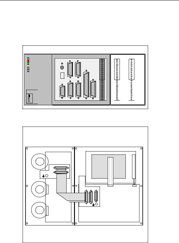
2.2Interfaces and cables
2.2Interfaces and cables
Position of the interfaces and front panel elements
|
|
ECU |
|
|
|
DI/O16 |
||
|
|
ENCODER1 ENCODER2 |
|
|
X10 |
X2003 |
X2005 |
|
|
|
X3 |
X4 |
|
|
MPG |
IN |
OUT |
ERR |
|
|
|
|
|
|
|
L+ |
|
|
|
|
|
|
0 |
0 |
|
|
|
|
|
|
|
|
||
POK |
S2 |
|
|
|
|
|
1 |
1 |
DIAG |
S3 |
|
|
|
|
|
2 |
2 |
|
|
|
|
|
|
3 |
3 |
|
|
|
|
|
|
|
|
4 |
4 |
|
|
|
|
|
|
|
5 |
5 |
|
D15 |
|
|
|
|
|
6 |
6 |
|
|
|
|
|
|
7 |
7 |
|
|
|
|
|
|
|
|
||
|
|
|
|
|
|
|
M |
M |
|
|
|
|
|
|
|
|
L+ |
|
|
|
|
|
|
|
8 |
8 |
|
|
|
|
|
|
|
9 |
9 |
|
|
|
|
|
|
|
10 |
10 |
DC24V X1 |
|
|
|
|
|
|
11 |
11 |
|
|
|
|
|
|
|
12 |
12 |
|
|
|
|
|
|
|
13 |
13 |
PE |
|
|
|
|
|
|
14 |
14 |
|
|
|
|
|
|
15 |
15 |
|
M |
|
|
|
|
|
|
||
|
|
|
|
|
|
M |
M |
|
L+ |
|
|
|
|
|
|
||
|
|
|
|
|
|
|
|
|
M |
RS232 |
ENCODER3 |
SPINDLE |
AXIS |
OPI |
DI |
X2004 |
X2006 |
|
X2 |
X5 |
X6 |
X7 |
X8 |
X20 |
||
Fig. 2-2 User interfaces
MCP |
OP020 |
|
Rear |
Rear |
|
X1202 |
CFL |
|
X1201 |
||
|
||
|
LCDsignal |
|
X1001 X1002 X1009 |
connector |
Fig. 2-3 Rear of machine control panel and operator panel
2-18 |
SINUMERIK 802S |
6FC5 597–2AA00–0BP2 (01.02) |

Installing the Control System
2.2 Interfaces and cables
Interfaces
SX1 power supply terminals (DC24V)
4–pin screw–terminal block for connecting the 24 V load power supply
SX2 RS232 interface (AXIS)
25–pin sub–D plug connector for connecting ther power sections for max. 4 stepper motor drives
SX3 spindle interface (SPINDLE)
9–pin D–Sub connector fr connecting a spindle drive with analog interface
SX4 measuring system interfaces (ENCD)
15–pin D–Sub female connector for connecting a position encoder (incremental, RS422)
SX8 RS232 drive interface (V24)
9–pin D–Sub connector
SX9 operator terminal interface (OPI)
25–pin D–Sub female connector for connecting the operator terminal
SX10 handwheel interface (MPG)
10–pin front connector for connecting the handwheels
SX20 BEROs (DI)
10–pin front connector for connecting fast inputs including BEROs and for wiring the NC READY relay
DI/O
SX2003 and X2004
10–pin front connector for connecting digital inputs
SX2005 and X2006
10–pin front connector for connecting digital outputs
LEDs
3 LEDs for fault and status displays
Operating elements
Start–up switch S1
SINUMERIK 802S |
2-19 |
6FC5 597–2AA00–0BP2 (01.02) |
Installing the Control System
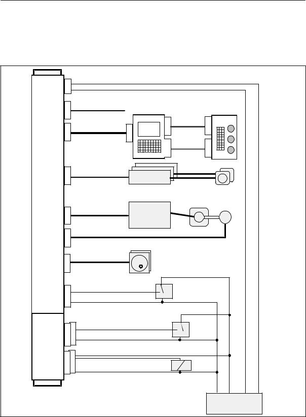
2.2Interfaces and cables
Connecting cables
The components are wired up as shown in the Connection Diagram 2-4. For the cables required, please refer to the diagram below.
DC24V |
X1 |
|
L+ |
|
|
|
|
|
|
|
|
M |
Wire (1.0...2.5) |
|
|
|
|
||||
ECU |
|
|
|
|
|
|||||
|
|
|
|
|
|
|
Machine |
|
||
|
|
|
|
|
|
|
|
|
||
|
X8 |
6FX6002-1AA01-... RS232 |
|
Control |
|
|||||
|
|
Panel |
|
|||||||
RS232 |
|
|
|
|
Op. Panel |
|
|
|||
|
|
|
|
|
X1009 |
X1002 X1001 |
1) |
X1201 |
|
|
OPI |
X9 |
6FX6002-1AA02-... |
|
|
|
|||||
|
|
|
|
Flat or round |
|
|
||||
|
|
|
|
cable 1) |
X1202 |
|
|
|||
|
|
|
|
|
|
|
||||
AXIS |
X2 |
6FX6002-3BA31-... |
STEP DRIVE |
|
|
|
|
|||
|
|
|
|
|
|
|
||||
|
|
|
|
|
|
|
STEPPER MOTOR |
|
||
|
X3 |
6FX6002-3AB01-... |
|
SPINDLE |
|
|
|
|
||
SPINDLE |
|
|
|
|
DRIVE |
|
|
|
|
|
|
X4 |
6FX6002-2CD01-... |
|
|
SPINDLE MOTOR |
|
|
|||
ENCODER |
|
|
|
|
|
ENCODER |
|
|
||
|
|
|
|
|
|
|
|
|
||
|
X10 |
6FX6002-2BB01-... |
|
|
|
|
|
|
||
MPG |
|
|
|
|
Handwheels |
|
|
|
||
|
|
|
|
|
|
|
|
|||
|
X20 |
|
IN |
|
|
|
Sensor (BERO) |
|
|
|
|
|
|
|
|
|
|
|
|||
DI |
|
M |
Wire (0.14...1.5) |
1...4 |
|
|
|
|||
|
|
|
|
|
||||||
DI/O16 |
X2003 |
X2004 |
IN |
|
|
|
|
Sensor |
|
|
|
|
|
|
1...16 |
|
|
||||
IN 0..7 |
|
Wire (0.14...1.5) |
|
|
|
|||||
M |
|
|
|
|
||||||
IN 8..15 |
|
|
|
|
|
|
|
|||
|
|
|
|
|
|
|
|
|||
|
X2005 |
X2006 |
L+ |
|
|
|
|
|
|
|
OUT0..7 |
OUT |
Wire (0.14...1.5) |
|
Actor |
|
|
||||
OUT8..15 |
|
|
|
|
||||||
M |
|
|
|
|
1...16 |
|
|
|||
|
|
|
|
|
|
|
||||
|
|
|
|
|
|
|
|
|||
|
|
|
|
|
|
|
|
M |
P24 |
M P24 |
|
|
|
|
|
|
|
|
Power Supply |
||
Fig. 2-4 SINUMERIK 802S Connection Diagram
1) Ribbon cable (included in scope of supply)
2-20 |
SINUMERIK 802S |
6FC5 597–2AA00–0BP2 (01.02) |
Installing the Control System
2.3 Connecting the individual components
2.3Connecting the individual components
Connecting the components
Note
Use only shielded cable and make sure that the shield is connected to the metal or metal plated connector casing on the control side. For the purpose of isolating the analog setpoint signal from low–frequency interference, we recommend not to ground the shield on the drive side.
The preassembled cable offered as accessories provides optimum protection against interference.
General procedure:
Proceed as follows to connect the individual components:
1.Connect the cables to the components as shown in Fig. 2-4.
2.Fix the sub–D connector in place using the knurled screws.
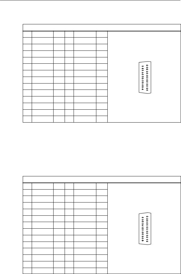
2.3.1Connecting the operator panel
Connector pin assignment on the ENC side
Operator panel interface |
|
Connector designation: |
X8 |
|
OP020 |
Connector type: |
25–pin sub–D plug connector |
SINUMERIK 802S |
2-21 |
6FC5 597–2AA00–0BP2 (01.02) |
Installing the Control System
2.3Connecting the individual components
Table 2-1 |
Pin assignment of connector X9 |
|
|
|
||||
|
|
|
|
|
|
X8 |
|
|
Pin |
Signal |
|
Type |
Pin |
Signal |
Type |
|
|
1 |
|
|
|
14 |
P24_OP |
VO |
|
|
2 |
M_OP |
|
VO |
15 |
OPD0_N |
O |
|
|
3 |
OPD0 |
|
O |
16 |
OPD1_N |
O |
|
|
4 |
OPD1 |
|
O |
17 |
OPD2_N |
O |
|
|
5 |
OPD2 |
|
O |
18 |
OPD3_N |
O |
25 |
13 |
|
|
|||||||
6 |
OPD3 |
|
O |
19 |
OPCP1_N |
O |
|
|
7 |
OPCP1 |
|
O |
20 |
OPCP2_N |
O |
|
|
8 |
OPCP2 |
|
O |
21 |
OPS_N |
O |
14 |
|
9 |
OPS |
|
O |
22 |
ENRXD_N |
I |
1 |
|
|
|
|||||||
|
|
|
||||||
10 |
ENRXD |
I |
23 |
ENTXD_N |
O |
|
|
|
11 |
ENTXD |
|
O |
24 |
ENRTS_N |
O |
|
|
12 |
ENRTS |
|
O |
25 |
P24_OP |
VO |
|
|
13 |
M_OP |
|
VO |
|
|
|
|
|
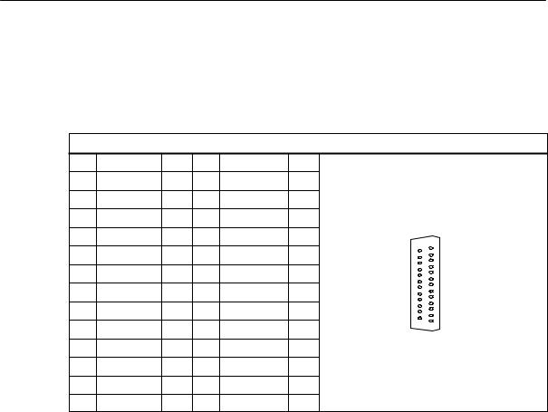
Connector pin assignment on the OP side
Operator panel interface |
|
|
|
|
||||
Connector designation: |
|
X1009 |
|
|
|
|||
|
|
|
|
|
OP020 |
|
|
|
Connector type: |
|
|
25–pin sub–D plug connector |
|
|
|||
Table 2-2 |
Pin assignment of connector X1009 |
|
|
|||||
|
|
|
|
|
|
X1009 |
|
|
Pin |
Signal |
|
Type |
Pin |
Signal |
Type |
|
|
1 |
|
|
|
14 |
P24_OP |
VI |
|
|
2 |
M_OP |
|
VI |
15 |
OPD0_N |
I |
|
|
3 |
OPD0 |
|
I |
16 |
OPD1_N |
I |
|
|
4 |
OPD1 |
|
I |
17 |
OPD2_N |
I |
|
|
5 |
OPD2 |
|
I |
18 |
OPD3_N |
I |
25 |
13 |
|
|
|
||||||
6 |
OPD3 |
|
I |
19 |
OPCP1_N |
I |
|
|
7 |
OPCP1 |
|
I |
20 |
OPCP2_N |
I |
|
|
8 |
OPCP2 |
|
I |
21 |
OPS_N |
I |
14 |
|
9 |
OPS |
|
I |
22 |
OPTXD_N |
O |
1 |
|
|
|
|
||||||
10 |
OPTXD |
|
O |
23 |
OPRXD_N |
I |
|
|
11 |
OPRXD |
I |
24 |
OPCTS_N |
I |
|
|
|
12 |
OPCTS |
|
I |
25 |
P24_OP |
VI |
|
|
13 |
M_OP |
|
VI |
|
|
|
|
|
2-22 |
SINUMERIK 802S |
6FC5 597–2AA00–0BP2 (01.02) |
|
|
Installing the Control System |
|
2.3 |
Connecting the individual components |
Signal names |
|
|
OPD[0...3] |
LCD Data 0...3 |
|
OPCP1 |
LCD Latch |
|
OPS |
LCD Frame |
|
OPCP2 |
LCD Clock |
|
OPRXD |
OP Receive Data |
|
OPTXD |
OP Transmit Data |
|
OPCTS |
OP Clear to Send |
|
ENRXD |
ECU Receive Data |
|
ENTXD |
ECU Transmit Data |
|
ENRTS |
ECU Request to Send |
|
P24_OP |
DC24V |
|
M_OP |
Ground |
|
Signal level |
|
|
RS422 / LVDS |
|
|
Signal type |
|
|
VO |
Voltage output |
|
VI |
Voltage input |
|
O |
Output |
|
I |
Input |
|
2.3.2Connecting the feed drives
Connector pin assignment on the ENC side
Feed drive interface
SINUMERIK 802S |
2-23 |
6FC5 597–2AA00–0BP2 (01.02) |
Installing the Control System
2.3Connecting the individual components
Connector designation: |
|
X2 |
|
|
||
|
|
|
|
AXIS 1-4 |
|
|
Connector type: |
|
50–pin sub–D plug connector |
|
|||
Table 2-3 |
Pin assignment of connector X1009 |
|
||||
|
|
|
|
|
X1009 |
|
Pin |
Signal |
Type |
Pin |
Signal |
Type |
|
1 |
|
|
14 |
P24_OP |
VI |
|
2 |
M_OP |
VI |
15 |
OPD0_N |
I |
|
3 |
OPD0 |
I |
16 |
OPD1_N |
I |
|
4 |
OPD1 |
I |
17 |
OPD2_N |
I |
13 |
5 |
OPD2 |
I |
18 |
OPD3_N |
25 |
|
I |
|
|||||
6 |
OPD3 |
I |
19 |
OPCP1_N |
I |
|
7 |
OPCP1 |
I |
20 |
OPCP2_N |
I |
|
8 |
OPCP2 |
I |
21 |
OPS_N |
I |
|
9 |
OPS |
I |
22 |
OPTXD_N |
14 |
1 |
O |
|
|||||
10 |
OPTXD |
O |
23 |
OPRXD_N |
I |
|
11 |
OPRXD |
I |
24 |
OPCTS_N |
I |
|
12 |
OPCTS |
I |
25 |
P24_OP |
VI |
|
13 |
M_OP |
VI |
|
|
|
|
Signal names |
|
|
PULS[1... |
4], PULS[1...4]_N |
Clock pulse, true and negated |
DIR[1...4], DIR[1...4]_N |
Direction signal, true and negated |
|
EN[1...4], EN[1...4]_N |
Servo enable, true and negated |
|
M |
|
Ground |
Signal level |
|
|
RS422 |
|
|
Signal type |
|
|
O |
Signal output |
|
Axis assignment
1X axis
2Y axis
3Z axis
4(reserved)
2-24 |
SINUMERIK 802S |
6FC5 597–2AA00–0BP2 (01.02) |

Installing the Control System
2.3 Connecting the individual components
Signals
One clock, direction and enable signal each is output per axis both as a true and a negated signal.
SPULS (CLOCK)
The clock pulses control the motor. With each rising pulse edge, the motor carries out a single step.
Thus, the angle of rotation, i.e. the distance to be traversed, is determined by the number of output pulses.
The rotational speed, i.e. the traversing speed, is determined by the pulse frequency.
SDIR (DIRECTION)
The direction of rotation of the motor is determined by the signal level.
Signal ON: |
”CCW rotation” |
Signal OFF: |
”CW rotation” |
SEN (ENABLE)
This signal is activated by the control system when the cyclic control mode is initiated.
Signal ON: |
Secondary power control enabled |
Signal OFF: |
Motor dead |
|
No readiness |
Signal parameters
All signals for stepper drives are output to the RS422 standard via differential signal cable drivers.
All outputs are eletcronically protected against short–circuit and thermal overload.
Table 2-4 |
Electrical parameters of the signal outputs for stepper drives |
|
|
||||
|
|
|
|
|
|
|
|
|
Parameter |
Min. |
Max. |
|
Unit |
at |
|
|
|
|
|
|
|
|
|
Differential output voltage |
VOD |
2 |
|
|
V |
RL = 100 Ω |
|
Output voltage ”high” |
VOH |
3.7 |
|
|
V |
IO = -20 mA |
|
4.5 |
|
|
V |
IO = -100 µA |
|||
|
|
|
|
|
|||
Output voltage ”low” |
VOL |
|
1 |
|
V |
IO = 20 mA |
|
Load resistance |
RL |
55 |
|
|
Ω |
|
|
Output current |
|
IO |
|
"60 |
|
mA |
|
Pulse frequency |
fP |
|
250 |
|
kHz |
|
|
Cable length: max. 50 m
(with asymmetric transfer 10 m)
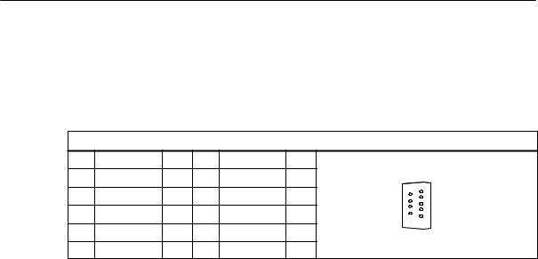
2.3.3Connecting the spindle drive (X3)
Pin assignment of the connector on the ENC side
Spindle drive interface
SINUMERIK 802S |
2-25 |
6FC5 597–2AA00–0BP2 (01.02) |
Installing the Control System
2.3Connecting the individual components
Connector designation: |
|
X3 |
|
|
|||
|
|
|
|
|
SPINDLE |
|
|
Connector type: |
|
|
9–pin D-Sub plug connector |
|
|||
Table 2-5 |
Belegung des Steckers X3 |
|
|
||||
|
|
|
|
|
|
X3 |
|
Pin |
Signal |
|
Type |
Pin |
Signal |
Type |
|
1 |
SW |
|
VO |
6 |
BS |
VO |
|
2 |
|
|
|
7 |
|
6 |
1 |
|
|
|
|
|
|||
3 |
|
|
|
8 |
|
9 |
5 |
|
|
|
|
|
|
||
4 |
|
|
|
9 |
RF.1 |
K |
|
5 |
RF.2 |
|
K |
|
|
|
|
for analog drives: |
|
|
|
|
|||
SW |
|
|
|
Setpoint |
|
|
|
BS |
|
|
|
Reference potential for setpoint (analog ground) |
|||
RF.1, |
RF.2 |
|
|
Servo enable contact |
|
||
Signal type |
|
|
|
|
|
|
|
VO |
|
|
Voltage output |
|
|
||
K |
|
|
Switching contact |
|
|
||
Drives with analog interface
Signals:
One voltage and one enable signal is provided.
SSW (SETPOINT)
Analog voltage signal in the range of "10 V to output a speed setpoint
SBS (REFERENCE SIGNAL)
Reference potential (analog ground) for the setpoint signal, internally connected to the logics ground
SRF (SERVO ENABLE)
Relay contact pair used to switch the enable signal for the power section, e.g. a SIMODRIVE unit. This signal is used by the ENC when the cyclic control mode is started.
Signal parameters
The setpoint is output as an analog differential signal.
Table 2-6 |
Electrical parameters of the spindle setpoint signal |
|
|
|
|
|
|
|
|
|
Parameter |
Min. |
Max. |
Unit |
|
|
|
|
|
Voltage range |
|
-10.5 |
10.5 |
V |
|
|
|
|
|
Output current |
|
-3 |
3 |
mA |
|
|
|
|
|
Relay contact
2-26 |
SINUMERIK 802S |
6FC5 597–2AA00–0BP2 (01.02) |
Installing the Control System
|
2.3 |
Connecting the individual components |
||
Table 2-7 |
Electrical parameters of the relay contacts |
|
||
|
|
|
|
|
|
Parameter |
|
Max. |
Unit |
|
|
|
|
|
Switching voltage |
|
50 |
V |
|
|
|
|
|
|
Switching current |
|
1 |
A |
|
|
|
|
|
|
Switching power |
|
30 |
VA |
|
|
|
|
|
|
Cable length: max. 35 m
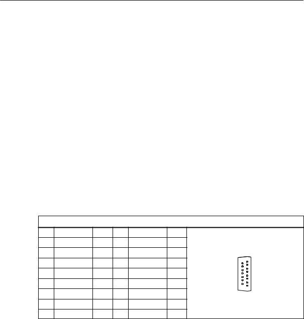
2.3.4Connecting the spindle measuring system (X4)
Pin assignment of the connector on the ENC side
Measuring system interface (incremental encoder)
Connector designation: |
|
X4 |
|
|
|
|||
|
|
|
|
|
ENCD |
|
|
|
Connector type: |
|
|
15–pin D-Sub female connector |
|
|
|||
Table 2-8 |
Pin assignment of the X4 female connector |
|
|
|||||
|
|
|
|
|
|
X4 |
|
|
Pin |
Signal |
|
Type |
Pin |
Signal |
Type |
|
|
1 |
|
|
|
9 |
M |
VO |
|
|
2 |
|
|
|
10 |
N |
I |
|
|
3 |
|
|
|
11 |
N_N |
I |
15 |
8 |
|
|
|
|
|
|
|
|
|
4 |
P5_MS |
|
VO |
12 |
B_N |
I |
|
|
5 |
|
|
VO |
13 |
B |
I |
9 |
1 |
6 |
P5_MS |
|
VO |
14 |
A_N |
I |
|
|
7 |
M |
|
VO |
15 |
A |
I |
|
|
8 |
|
|
|
|
|
|
|
|
Signal names |
|
|
|
|
|
|
||
A, A_N |
|
Track A (true and negated) |
|
|
||||
B, B_N |
|
Track B (true and negated) |
|
|
||||
N, N_N |
|
Zero mark (true and negated) |
|
|
||||
P5_MS |
|
+5.2 V supply |
|
|
|
|||
M |
|
|
Supply ground |
|
|
|
||
SINUMERIK 802S |
2-27 |
6FC5 597–2AA00–0BP2 (01.02) |

Installing the Control System
2.3Connecting the individual components
Signal level |
|
RS422 |
|
Signal type |
|
VO |
Voltage output (supply) |
I |
5V input (5V signal) |
Encoder types which can be connected
Incremental 5 V encoders can be connected directly.
Characteristics
The encoders must meet the following requirements:
Transmission method: Differential transmission with 5 V square–wave
|
signals |
||||
Output signals: |
Track A as true and negated signal (Ua1, |
|
) |
||
Ua1 |
|||||
|
Track B as true and negated signal (Ua2, |
Ua2 |
) |
||
|
Zero signal N as true and negated signal |
||||
|
(Ua0, |
|
) |
||
|
Ua0 |
||||
Max. output frequency: 1.5 MHz |
|||||
Phase offset between |
|
|
|
|
|
tracks A and B: |
90° "30° |
|
|
||
Current consumption: |
max. 300 mA |
||||
Cable lengths
The maximum cable length depends on the specification of the encoder supply and on the transmission frequency. When using preassembled cables from SIEMENS, the following values may not be exceeded to ensure interference–free operation:
Table 2-9 |
Maximum cable length with respect to the encoder supply |
||||||
|
|
|
|
|
|
|
|
Supply Voltage |
Tolerance |
|
Current |
|
Max. |
||
|
Consumption |
|
Cable Length |
||||
|
|
|
|
|
|
||
|
|
|
|
|
|
|
|
5 V DC |
|
4.75 V...5.25 V |
|
< 300 mA |
|
25 m |
|
|
|
|
|
|
|
|
|
5 V DC |
|
4.75 V...5.25 V |
|
< 220 mA |
|
35 m |
|
|
|
|
|
|
|
||
Table 2-10 Maximum cable lengths with respect to the transmission frequency |
|||||||
|
|
|
|
|
|||
Encoder Type |
|
|
Frequency |
|
Max. Cable Length |
||
|
|
|
|
|
|
||
Incremental |
|
|
1 MHz |
|
10 m |
||
|
|
|
|
|
|
|
|
|
|
500 kHz |
35 m |
||||
|
|
|
|||||
|
|
|
|
|
|
|
|
2-28 |
SINUMERIK 802S |
6FC5 597–2AA00–0BP2 (01.02) |

Installing the Control System
2.3 Connecting the individual components
2.3.5Configuration of the RS232 interface connection (X8)
Pin assignment of the connector on the ENC side
RS232 interface |
|
|
|
|
|
|
||||
Connector designation: |
|
X8 |
|
|
|
|
||||
|
|
|
|
|
|
RS232 |
|
|
|
|
Connector type: |
|
|
|
|
9–pin sub–D plug connector |
|
|
|||
Table 2-11 Pin assignment of connector X8 |
|
|
|
|
||||||
|
|
|
|
|
|
|
|
|
|
|
|
|
|
|
|
|
|
X8 |
|
|
|
|
|
|
|
|
|
|
|
|
|
|
Pin |
Name |
|
Type |
Pin |
Name |
Type |
|
|
|
|
|
|
|
|
|
|
|
|
|
|
|
1 |
|
|
|
|
6 |
DSR |
I |
|
|
1 |
|
|
|
|
|
|
|
|
|
6 |
|
2 |
RxD |
|
I |
7 |
RTS |
O |
|
|||
|
|
|
||||||||
|
|
|
|
|||||||
|
|
|
|
|
|
|
|
|
9 |
5 |
3 |
TxD |
|
O |
8 |
CTS |
I |
|
|||
|
|
|
||||||||
|
|
|
|
|
|
|
|
|
|
|
4 |
DTR |
|
O |
9 |
|
|
|
|
|
|
|
|
|
|
|
|
|
|
|
|
|
5 |
M |
|
VO |
|
|
|
|
|
|
|
|
|
|
|
|
|
|
|
|
|
|
Signal description: |
|
|
|
|
|
|
||||
RxD |
|
|
|
|
Receive data |
|
|
|
|
|
TxD |
|
|
|
|
Send data |
|
|
|
|
|
RTS |
|
|
|
|
Request to send |
|
|
|||
CTS |
|
|
|
|
Send enable |
|
|
|
|
|
DTR |
|
|
|
|
Standby output |
|
|
|
|
|
DSR |
|
|
|
|
Standby input |
|
|
|
|
|
M |
|
|
|
|
Ground |
|
|
|
|
|
Signal level |
|
|
|
|
|
|
|
|
|
|
RS232 (+ 12 V) |
|
|
|
|
|
|
|
|
|
|
Signal type |
|
|
|
|
|
|
|
|
|
|
I |
|
Input |
|
|
|
|
|
|
||
O |
|
Output |
|
|
|
|
|
|
||
VO |
|
Voltage output |
|
|
|
|
||||
Cable for WinPCIN |
|
|
|
|
|
|
||||
Table 2-12 Cable for WinPCIN: Pin assignment of the Sub–D connector |
|
|||||||||
|
|
|
|
|
|
|
|
|
|
|
|
9–Pin |
|
|
|
|
|
Name |
|
25–Pin |
|
|
|
|
|
|
|
|
|
|
|
|
|
1 |
|
|
|
|
|
Shield |
|
1 |
|
|
|
|
|
|
|
|
|
|
|
|
|
2 |
|
|
|
|
|
RxD |
|
2 |
|
|
|
|
|
|
|
|
|
|
|
|
|
3 |
|
|
|
|
|
TxD |
|
3 |
|
|
|
|
|
|
|
|
|
|
|
|
|
4 |
|
|
|
|
|
DTR |
|
6 |
|
|
|
|
|
|
|
|
|
|
|
|
|
5 |
|
|
|
|
|
M |
|
7 |
|
|
|
|
|
|
|
|
|
|
|
|
|
6 |
|
|
|
|
|
DSR |
|
20 |
|
|
|
|
|
|
|
|
|
|
|
|
|
7 |
|
|
|
|
|
RTS |
|
5 |
|
|
|
|
|
|
|
|
|
|
|
|
SINUMERIK 802S |
2-29 |
6FC5 597–2AA00–0BP2 (01.02) |

Installing the Control System
2.3Connecting the individual components
Table 2-12 Cable for WinPCIN: Pin assignment of the Sub–D connector
8 |
CTS |
4 |
|
|
|
9 |
|
|
|
|
|
2.3.6Connecting handwheels (X10)
Pin assignment of the connector on the ENC side
Handwheel interface
Connector designation: |
X10 |
|||
|
|
|
MPG |
|
Connector type: |
|
10–pin mini-Combicon plug connector |
||
Table 2-13 Pin assignment of connector |
||||
|
X10 |
|
|
|
|
|
X10 |
|
|
Pin |
Name |
Type |
|
|
1 |
A1 |
I |
|
|
2 |
A1_N |
I |
1 |
|
3 |
B1 |
I |
||
|
||||
4 |
B1_N |
I |
|
|
5 |
P5_MS |
VO |
|
|
6 |
M5_MS |
VO |
|
|
7 |
A2 |
I |
|
|
8 |
A2_N |
I |
10 |
|
9 |
B2 |
I |
|
|
10 |
B2_N |
I |
|
|
Signal names
A1, A1_N B1, B1_N A2, A2_N B2, B2_N P5_MS M
Signal level
RS422
Signal type
Track A, true and negated (handwheel 1) Track B, true and negated (handwheel 1) Track A, true and negated (handwheel 2) Track B, true and negated (handwheel 2) 5.2 V supply voltage for handwheels Supply ground
2-30 |
SINUMERIK 802S |
6FC5 597–2AA00–0BP2 (01.02) |
 Loading...