


 Loading...
INTEGRATED CIRCUITS
TEA5591
AM/FM radio receiver circuit
Product specification |
|
June 1989 |
|||||
File under Integrated Circuits, IC01 |
|
|
|
|
|
|
|
|
|
|
|
|
|
|
|
|
|
|
|
|
|
|
|
|
|
|
|
|
|
|
|

Philips Semiconductors |
Product specification |
|
|
AM/FM radio receiver circuit |
TEA5591 |
|
|
|
|
GENERAL DESCRIPTION
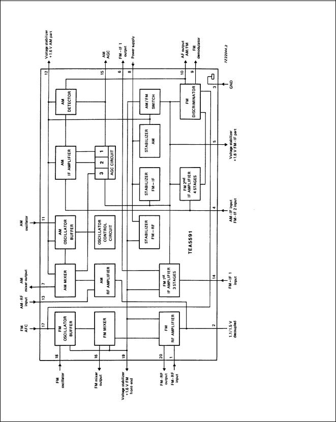
The TEA5591 is an integrated radio circuit which is designed for use in portable receivers and clock radios. The IC is also applicable to mains-fed AM an AM/FM receivers and car radio-receivers. The main advantage of this IC is its ability to operate over a wide range of supply voltages without loss of performance. The AM circuit incorporates a balanced mixer and a ‘one-pin’ oscillator, which operates in the 0.6 MHz to 30 MHz frequency range, with amplitude control. The circuit also includes an IF amplifier, a detector and an AGC circuit which controls the IF amplifier and the mixer. The FM circuit incorporates an RF amplifier, a balanced mixer and a ‘one-pin’ oscillator together with two AC coupled IF amplifiers (with distributed selectivity), a quadrature demodulator for the ceramic filter and internal AFC.
Features
∙DC AM/FM switch facility
∙Three internal separate stabilizers to enable operation over a wide range of supply voltages (1.8 to 15 V)
∙All pins (except pin 9) are ESD protected.
QUICK REFERENCE DATA
PARAMETER |
CONDITIONS |
SYMBOL |
MIN. |
TYP. |
MAX. |
UNIT |
|
|
|
|
|
|
|
Supply voltage (pin 8) |
|
VP |
1.8 |
3.0 |
15 |
V |
Supply current |
|
|
|
|
|
|
AM part |
|
IP(AM) |
− |
14 |
19 |
mA |
FM part |
|
IP(FM) |
− |
17 |
23 |
mA |
Operating ambient temperature range |
|
Tamb |
−15 |
− |
+60 |
°C |
AM performance (pin 13) |
m = 0.3 |
|
|
|
|
|
RF sensitivity |
|
|
|
|
|
|
RF input voltage |
Vo = 10 mV |
Vi |
− |
3.5 |
− |
μ V |
RF input voltage |
(S+N)/N = 26 dB |
Vi |
− |
17 |
− |
μV |
Signal plus noise-to-noise ratio |
Vi = 1 mV |
(S+N)/N |
− |
48 |
− |
dB |
AF output voltage |
|
Vo |
− |
50 |
− |
mV |
Total harmonic distortion |
|
THD |
− |
0.7 |
− |
% |
FM performance (pin 1) |
f = 22.5 kHz |
|
|
|
|
|
RF sensitivity |
|
|
|
|
|
|
RF input voltage |
|
|
|
|
|
|
−3 dB before limiting |
|
Vi |
− |
2.3 |
4.0 |
μV |
Signal plus noise-to-noise ratio for: |
|
|
|
|
|
|
RF input signal voltage (Vi) |
Vi = 3.0 μV |
(S+N)/N |
23 |
26 |
− |
dB |
|
Vi = 1 mV |
(S+N)/N |
− |
60 |
− |
dB |
AF output voltage |
Vi = 100 μV |
Vo |
75 |
90 |
− |
mV |
Total harmonic distortion |
|
THD |
− |
0.8 |
− |
% |
|
|
|
|
|
|
|
PACKAGE OUTLINE
20-lead DIL; plastic (SOT146); SOT146-1; 1996 August 14.
June 1989 |
2 |
Philips Semiconductors |
Product specification |
|
|
AM/FM radio receiver circuit |
TEA5591 |
|
|
Fig.1 Block diagram.
June 1989 |
3 |

Philips Semiconductors |
Product specification |
|
|
AM/FM radio receiver circuit |
TEA5591 |
|
|
Fig.2 Equivalent circuit diagram.
June 1989 |
4 |
Philips Semiconductors |
Product specification |
|
|
AM/FM radio receiver circuit |
TEA5591 |
|
|
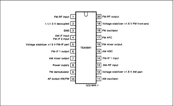
PINNING |
|
Fig.3 Pinning diagram.
June 1989 |
5 |

Philips Semiconductors |
|
|
|
Product specification |
||
|
|
|
|
|
|
|
AM/FM radio receiver circuit |
|
|
|
TEA5591 |
||
|
|
|
|
|
|
|
RATINGS |
|
|
|
|
|
|
Limiting values in accordance with the Absolute Maximum System (IEC 134) |
|
|
|
|||
|
|
|
|
|
|
|
PARAMETER |
|
CONDITIONS |
SYMBOL |
MIN. |
MAX. |
UNIT |
|
|
|
|
|
|
|
Supply voltage (pin 8) |
|
|
VP |
− |
18 |
V |
Storage temperature range |
|
|
Tstg |
−65 |
+ 150 |
°C |
Operating ambient temperature range |
|
|
Tamb |
−15 |
+ 60 |
°C |
Total power dissipation |
|
|
Ptot |
see Fig.4 |
|
|
Fig.4 Power derating curve.
June 1989 |
6 |

Philips Semiconductors |
Product specification |
|
|
AM/FM radio receiver circuit |
TEA5591 |
|
|
DC CHARACTERISTICS
All voltages are referenced to pin 3; all input currents are positive; all parameters are measured in Fig.5 at nominal supply voltage VP = 3 V; Tamb = 25 °C unless otherwise specified
PARAMETER |
CONDITIONS |
SYMBOL |
MIN. |
TYP. |
MAX. |
UNIT |
|
|
|
|
|
|
|
Supply voltage |
|
VP |
1.8 |
3.0 |
15 |
V |
Voltages (FM) |
|
|
|
|
|
|
pin 1 |
|
V1 |
− |
0.90 |
− |
V |
pin 2 |
|
V2 |
− |
1.60 |
− |
V |
pin 4 |
|
V4 |
− |
0.85 |
− |
V |
pin 5 |
|
V5 |
1.5 |
1.60 |
1.75 |
V |
pin 6 |
|
V6 |
− |
1.48 |
− |
V |
pin 9 |
|
V9 |
− |
1.05 |
− |
V |
pin 14 |
|
V14 |
− |
1.63 |
− |
V |
pin 17 |
|
V17 |
− |
0.60 |
− |
V |
pin 19 |
|
V19 |
− |
1.60 |
− |
V |
Voltages (AM) |
|
|
|
|
|
|
pin 2 |
|
V2 |
− |
1.10 |
− |
V |
pin 12 |
|
V12 |
− |
1.60 |
− |
V |
pin 15 |
|
V15 |
− |
1.54 |
− |
V |
Supply current |
|
|
|
|
|
|
AM part |
|
IP(AM) |
− |
14 |
19 |
mA |
FM part |
|
IP(FM) |
− |
17 |
23 |
mA |
June 1989 |
7 |
Loading...