


General Installation Manual
Photovoltaic Module HIT®
VBHNxxxSA series
VBHNxxxKA series
Model No.VBHNxxxSA17
xxx=330, 325VBHNxxxKA03 xxx=325, 320
VBHNxxxSA17 series |
VBHNxxxKA03 series |
Thank you for choosing Panasonic photovoltaic module HIT®. Please read this manual completely before you install or use of HIT®. With proper operation and maintenance, HIT® will provide you with clean, renewable solar electricity for many years. This manual contains important installation, maintenance and safety information. The word “module” as used in this manual refers to one or more PV modules. Retain this manual for future reference.
CONTENTS
SAFETY PRECAUTIONS |
2 |
GENERAL INFORMATION |
|
WARNING |
|
CAUTIONS |
|
MODULE SPECIFICATIONS |
3 |
MECHANICAL LOADING |
|
STANDARDS |
5 |
FIRE CLASS OF PRODUCT |
|
BYPASS DIODE |
|
INSTALLATION |
6 |
GENERAL |
|
OPERATING CONDITIONS |
|
SPECIAL CONDITIONS |
|
UNPACKING AND HANDLING |
|
MODULE INSTALLATION |
|
WIRING |
8 |
GENERAL |
|
MODULE WIRING |
|
ARRAY WIRING |
|
EARTH GROUND WIRING |
|
GROUNDING METHODS |
|
MAINTENANCE |
13 |
ANTI-REFLECTION GLASS SURFACE |
|
CLEANING |
|
DISCLAIMER OF LIABILITY |
13 |
CONTACT INFORMATION |
13 |
|
“HIT” is a trademark of the Panasonic Group.
Other product and service names listed in this manual are trademarks or registered trademarks of respective companies.

SAFETY PRECAUTIONS
All instructions should be read and understood before attempting to install, wire, operate, and maintain the module.
The installation of modules requires a great degree of skill and should only be performed by qualified licensed professionals, including, without limitation, licensed contractors and licensed electricians.
The installer assumes the risk of all injury that might occur during installation, including, without limitation, the risk of electric shock.
Before installing modules, contact the appropriate authorities to determine permissions, installation and inspection requirements, which should be followed.
Be sure that the construction or structure (roof, etc.) where the modules are being installed has enough strength.
Both roof construction and module installation design have an effect on the fire resistance of a building.
Improper installation may contribute to fire hazards. Additional devices such as ground fault, fuses, and disconnects may be required.
For a non-integral module or panel, the assembly is to be mounted over a fire resistant roof covering rated for the application.
For modules mounted on roofs, special construction or structures may be required to help provide proper installation support.
Do not install the module where flammable gases or vapors are present.
Do not use modules of different specifications in the same system.
Follow all safety precautions of other system components used.
In some areas, local electrical codes may govern the installation and use of modules.
WARNING |
CAUTIONS |
To avoid the hazard of electric shock, sparks, fire and injury
The modules generate DC electrical energy when exposed to sunlight or other light sources, so cover the entire front surface of the modules with a dense, opaque material such as a cardboard box, during installation and handling of the modules.
The shock hazard increases as modules are connected in parallel, producing higher current, and as modules are connected in series, producing higher voltages.
The shock hazard increases as modules with nominal open-circuit voltage (Voc) in excess of 50 V, and/or modules rated for maximum system voltage in excess of 50 V.
Wear suitable clothing, gloves and guards to prevent from direct contact with 30 VDC or greater.
Work only in dry conditions, with dry modules and dry tools.
Children and unauthorized persons should not be allowed near the installation of modules.
Do not puncture or damage the back sheet of a module.
Do not disassemble the module, or remove any parts installed by the manufacturer.
Do not open a junction box's lid.
Do not touch the junction box terminals.
Do not change the wiring of bypass diodes.
Do not connect or disconnect terminals while modules generate electricity and connect electrical load.
Never leave a module unsupported or unsecured.
To avoid the hazard of injury, burn and damage to the module
Use a module for its intended purpose only.
Be sure that all other system components are compatible, and they do not subject the module to mechanical or electrical hazards.
Do not artificially concentrate sunlight on a module.
Do not stand or step on a module.
When carrying a module, two or more people should carry it by its frame and wear non-slip gloves.
Do not carry a module by its wires or junction box.
Do not drop a module.
Do not drop anything on the surface of a module.
Do not hit the back sheet of a module by the connector or other things.
Do not disassemble a module, attempt any repair, open the junction box cover, nor remove any parts installed by Panasonic. There are no user serviceable parts within the module or junction box.
Do not treat the back sheet or front surface with paint or adhesives.
Do not use or install broken modules.
Do not touch a module unnecessarily. The glass surface and frames get hot.
2
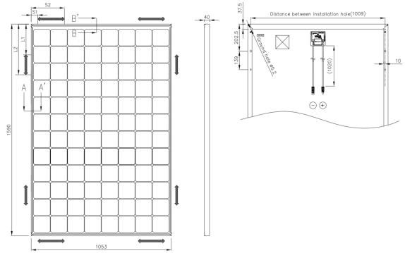
MODULE SPECIFICATIONS
Module specifications are shown in Table 1 and Figure 1. (Electrical specifications, mechanical specifications, module dimensions)
1)Rated electrical characteristics are within the range of –5% to +10% of the values measured at Standard Test Conditions (STC). STC conditions are; Irradiance of 1000W/m2, 25°C cell temperature, AM1.5 and solar spectral irradiance per IEC 60904-3. Note: At the time of shipment, Panasonic guarantees the output level of its modules to be -0/ +10% against Rated Power in SPECIFICATIONS based on factory inspection at STC conditions.
2)Under real conditions, a photovoltaic module may experience conditions that produce more current and/or voltage than reported at Standard Test Conditions. Therefore, the Isc value of modules should be multiplied by a factor of 1.25 to determine ampacity. An
additional factor of 1.25 may be required for sizing conductors, fuses, disconnects, etc. Please refer to section 690.8 of the National Electric Code (NEC) for guidelines. The Voc must be factored according to the lowest recorded ambient temperature recorded for the location where the modules will be installed. Please refer to section 690.7 of the NEC for more information regarding voltage temperature factors.
MECHANICAL LOADING
The modules should be mounted at the four (4) quarter points by the means shown in Figure 1.
This method offers a maximum load shown as “Mount Location and Load Resistance” in Figure 1 in a static state on the module surface.
Note: This mechanical loading value was tested using the mounting device specified in section “MODULE INSTALLATION”
As UL Certified Load Ratings, this module meets design loads as below.
1)Positive load with Long frame mounting
33 psf (0-450mm range from edge
75 psf (230-380mm range from edge)
2)Negative load with Long frame mounting
33 psf (0-450mm range from edge
61 psf(230-380mm range from edge)
75 psf (230-345mm range from edge)
3)Positive load with Short frame mounting
33 psf (0-250mm range from edge)
4)Negative load with Short frame mounting
33 psf (0-250mm range from edge)
Dimension in mm
Backside
Mount Locations and Load Resistance
|
L1 |
0 |
230 |
230 |
- |
|
Mounting location range |
L2 |
450 |
380 |
345 |
- |
|
S1 |
- |
- |
- |
0 |
||
|
||||||
|
S2 |
- |
- |
- |
250 |
|
Load Resistance (Positive Load) |
50 psf |
112 psf |
112 psf |
50 psf |
||
(2400 Pa) |
(5400 Pa) |
(5400 Pa) |
(2400 Pa) |
|||
|
|
|||||
|
|
|
|
|
|
|
Load Resistance (Negative Load) |
50 psf |
91 psf |
112 psf |
50 psf |
||
(2400 Pa) |
(4400 Pa) |
(5400 Pa) |
(2400 Pa) |
|||
|
|
|||||
Note) Load Resistance shown above is UL Test-Load.
Design load is a value obtained by multiplying the above value by two thirds.
Side
Front
Note) A module is installed using 4 points, symmetrical mounting within setting range (shaded).
Setting range parameters are shown in “Mount Locations and Load Resistance” table.
Figure 1. Module Dimension
3
Table 1. Model Specifications
Electrical Specifications
Model |
VBHN330SA17 |
VBHN325SA17 |
VBHN325KA03 |
VBHN320KA03 |
|
|
|
|
|
Cell Number in Series |
96 |
96 |
96 |
96 |
Rated Power, Watts (Pmax) |
330 |
325 |
325 |
320 |
|
|
|
|
|
|
58.0 |
57.6 |
59.2 |
58.7 |
Maximum Power Voltage |
|
|
|
|
|
5.70 |
5.65 |
5.50 |
5.46 |
Maximum Power Current |
|
|
|
|
Open Circuit Voltage (Voc) |
69.7 |
69.6 |
70.9 |
70.5 |
|
|
|
|
|
Short Circuit Current (Isc) |
6.07 |
6.03 |
5.94 |
5.89 |
|
|
|
|
|
Cell Type |
Silicon hetero- |
Silicon hetero- |
Silicon hetero- |
Silicon hetero- |
junction* |
junction* |
junction* |
junction* |
|
Maximum System Voltage |
600 |
600 |
600 |
600 |
Factory Installed Bypass |
|
|
|
|
Diodes |
4 |
4 |
4 |
4 |
Maximum series fuse (A) |
15 |
15 |
15 |
15 |
Silicon hetero-junction*: Monocrysttaline silicon/amorphous silicon hetero-junction Mechanical Specifications
Length, mm (inches) |
1590 (62.60) |
Width, mm (inches) |
1053 (41.46) |
Frame Depth, mm (inches) |
40 (1.57) |
Weight, kg (pounds) |
19 (41.89) |
4
STANDARDS
VBHNxxxSA and VBHNxxxKA series comply with the requirements of UL1703.
FIRE CLASS OF PRODUCT
The fire rating of this module is valid only when mounted in the manner specified in the mechanical mounting instructions.
The models in this instructions are suitable to maintain the System Fire Class Rating A when used with a Listed mounting system and a roof covering that have been rated as a Class A System when installed on a steep slope roof and/or a low slope roof with "Type 2" modules.
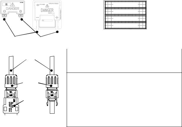
JUNCTION BOX AND TERMINALS
Modules equipped with one junction box contain terminals for both positive and negative polarity, and bypass diodes.
Each terminal is dedicated to one polarity (with the polarity symbols engraved onto the body of the junction box) (see Figure 2).
Each terminal is provided with factory installed lead cables and a latch-
ing connector for series and string connections. Always use these connectors and do not detach them from cables.
The PV module comes pre-wired. Each module has two #12 AWG type PV-wire stranded sunlight resistant output cables each terminated with connectors. The positive (+) terminal has a male connector while the negative (-) terminal has a female connector. The module wiring is solely for series connections only, i.e. male
(+) to female (-) interconnections. When making field wiring connections to the preattached connectors use only approved connectors from Table.2.
Latching connectors are type IV and made by STAUBLI ELECTRICAL CONNECTORS AG. Supplied connectors listed by UL.
In order to comply with NEC 2008, a locking sleeve needs to be used with all connectors that are exposed.
The locking sleeve (PV-SSH4) is made by STAUBLI and can only be released with a special tool also made by STAUBLI (PV-MS). Locking sleeves are not supplied with mod-
ules and must be purchased separately.
BYPASS DIODE
When the modules in series strings are shaded partially, it may cause reverse voltage across cells or modules, because the current from other cells in the same series is forced to flow through the shaded area. This may cause undesirable heating to occur.
The use of a diode to bypass the shaded area can minimize both heating and array current reduction.
All modules are equipped with factory installed bypass diodes. The factory installed diodes provide proper circuit protection for the systems within the specified system voltage, so that you do not need any other additional bypass diodes.
Specifications of bypass diode for VBHNxxxSA and VBHNxxxKA modules are as follows; Type: Number of bypass diode: 4 diodes, Number of series cells per bypass diode: 24 cells / diode (See Figure 3).
24 cells /
24 cells /
24 cells /
24 cells /
Figure 3. Number of series cells per bypass diode
Negative ( - ) |
Positive ( + ) |
Table.2 Approved connectors list
Figure 2. Junction Box
Cable
Connector
Option:
Safety lock
Negative ( - ) |
Positive ( + ) |
Figure 2. Connectors
Manufacturer |
STAUBLI ELECTRICAL CONNECTORS AG |
|
|
Contact Information |
http://ec.staubli.com |
|
|
|
Model # |
PV-KST4, PV-KBT4 followed by /2.5 or /6, followed by "I" or "II", followed by -UR. or - may be followed by additional suffixes, may be followed by suffix numbers and letters.
PV-PLS-S, PV-PLS-B, may be followed by suffix numbers and letters, may be followed by suffix numbers and letters.
Male PV connectors,
PV-KST4-EVO2/2.5, 6 or 10, followed by I, II, III or IV, followed by -UR.
Female PV connectors,
PV-KBT4-EVO2/2.5, 6 or 10, followed by I, II, III or IV, followed by –UR
5
 Loading...