


 Loading...
Voice Processing System
Installation Manual
VOICE PROCESSING SYSTEM
POWER
Model
KX-TVS50 KX-TVS80
Thank you for purchasing a Panasonic Voice Processing System, Model KX-TVS50/KX-TVS80. Please read this manual before installing, customizing, or operating the Voice Processing System.

Thank you for purchasing the Panasonic Model
KX-TVS50/KX-TVS80 Voice Processing System.
We are confident that it will provide your customer or client with many years of dependable service.
This Voice Processing System was especially tailored for the American environment. For example, it can be configured for English, a second language, or a third language:
System prompts—Recorded by the factory in English User 1 prompts—Record in any language you like User 2 prompts—Record in any language you like
These prompts guide subscribers and non-subscribers through specific VPS operations.
However, we would like to stress that for outside callers who merely need to be guided to an extension, a mailbox, or other destinations (e.g., a fax machine), they can be greeted by a Custom Service. This supports many languages as there are 12 keys on a touchtone phone and you can record up to 100 Custom Service menus. One twelfth of these menus can be recorded in one language if you desire. Another twelfth can be recorded in another language, and so on. Thus callers can be guided entirely in their native languages. For a multi-cultural United States, Custom Service is a truly powerful feature. Please see "Custom Service" in Appendix
A1 SYSTEM FEATURES for more details.
Note
This product is only for connection behind a suitable PBX and should not be connected directly to the network.
Panasonic World Wide Web Address: http://www.panasonic.com for customers in the United States or Puerto Rico.
2 |
Installation Manual |

Important Information
Important Information
SAFETY REQUIREMENTS
•Follow all product warnings, cautions, and instructions.
•Handle the unit carefully. Do not drop or otherwise expose the unit to physical shock.
•If the unit malfunctions, disconnect the unit from the telephone line and check the line by reconnecting the telephone. If the telephone operates properly, have the VPS repaired by a qualified Panasonic Factory Service Technician.
•Install the unit so that the power cord is not obstructed in any way. Do not connect this unit to an extension cord.
•Keep the unit free of dust, moisture, condensation, high temperature exposure (more than 40 °C {104 °F}) and vibration. Do not expose the unit to direct sunlight.
•Mount the unit on a stable wall surface. Do not mount the VPS inside of a separate enclosure unless it is properly ventilated.
•Read all the information contained in this manual.
•This unit is designed to operate at one specific voltage and current setting. The proper voltage and current required for this unit are listed on the product label.
•This unit is equipped with a 3-wire grounding plug. The plug will only fit into a grounded power outlet. Do not modify this plug in any way. If it cannot be inserted into the outlet, have the outlet replaced by a licensed electrician.
•Unplug and transport the unit to a service technician if the power supply cord is frayed or damaged, if the cabinet is cracked or broken, or when the unit has been exposed to moisture, has been dropped, or is not otherwise operating properly.
•Unplug the unit from its power source before cleaning.
•Do not block the vent slots and openings located on the front and top of the unit.
•Do not disassemble this product. Dangerous electrical shock could result. The unit must only be disassembled and repaired by qualified Panasonic Factory Service Technicians.
•Do not insert wires, pins, or any other material into the unit's vent slots or access points. This could result in electrical shock and serious unit malfunction.
•Do not install the unit near water or moisture, heating appliances, or electrical noise generating devices such as televisions, monitors, fluorescent lamps, or electric motors.
•Do not overload wall outlets. Overloaded outlets could result in fire and/or electrical shock.
•Do not use solvents, liquid cleaners, water, or abrasive powders to clean this unit. Use only a damp soft cloth for cleaning.
•Do not use the telephone during a lightning storm or to report a gas leak in the vicinity of the leak.
WARNING
TO PREVENT FIRE OR ELECTRICAL SHOCK, DO NOT EXPOSE THIS UNIT TO RAIN OR MOISTURE.
Installation Manual |
3 |

Important Information
When you ship the product
Carefully pack and send it prepaid, adequately insured and preferably in the original carton. Attach a postage-paid letter, detailing the symptom, to the outside of the carton. DO NOT send the product to the Executive or Regional Sales offices. They are NOT equipped to make repairs.
Product service
Panasonic Factory Servicenters for this product are listed in the servicenter directory. Consult your authorized Panasonic dealer for detailed instructions.
The serial number of this product may be found on the label affixed to the back of the unit. You should note the serial number of this unit in the space provided and retain this book as a permanent record of your purchase to aid in identification in the event of theft.
MODEL NO.:
SERIAL NO.:
For your future reference
DATE OF PURCHASE
NAME OF DEALER
DEALER’S ADDRESS
DEALER’S TEL. NO.
WARNING
THIS UNIT MAY ONLY BE INSTALLED AND SERVED BY QUALIFIED SERVICE PERSONNEL.
WHEN A FAILURE OCCURS WHICH RESULTS IN THE INTERNAL PARTS BECOMING ACCESSIBLE, DISCONNECT THE POWER SUPPLY CORD IMMEDIATELY AND RETURN THIS UNIT TO YOUR DEALER.
DISCONNECT THE TELECOM CONNECTION BEFORE DISCONNECTING THE
4 |
Installation Manual |

Important Information
POWER CONNECTION PRIOR TO RELOCATING THE EQUIPMENT, AND RECONNECT THE POWER FIRST.
THIS UNIT IS EQUIPPED WITH AN EARTHING CONTACT PLUG. FOR SAFETY REASONS, THIS PLUG MUST ONLY BE CONNECTED TO AN EARTHING CONTACT SOCKET WHICH HAS BEEN INSTALLED ACCORDING TO REGULATIONS.
CAUTION
Danger of explosion if battery is incorrectly replaced.
Replace only with the same or equivalent type recommended by the manufacturer.
Dispose of used batteries according to the manufacturer's instructions.
Note
Before you start setting or changing system parameters, we recommend that you turn off the Call Progression Mode with the OFLN command. While off, the power LED of the VPS will flash and the VPS will not answer any incoming call. After you finish programming, use the ONLN command to turn on the Call Progression Mode (normal operation). Please see
7.2.1Off-line Set (OFLN) and 7.2.2 On-line Set (ONLN) for more details.
Trademarks
•HyperTerminal is either a registered trademark or a trademark of HILGRAEVE, INCORPORATED in the United States and/or other countries.
•IBM is either a registered trademark or a trademark of International Business Machines Corporation in the United States and/or other countries.
•Procomm Plus is either a registered trademark or a trademark of DATASTORM TECHNOLOGIES, INC. in the United States and/or other countries.
•Smartcom is either a registered trademark or a trademark of Hayes Microcomputer Products, Inc. in the United States and/or other countries.
•All other trademarks identified herein are the property of their respective owners.
Installation Manual |
5 |

Important Information
TELEPHONE COMPANY AND F.C.C. REQUIREMENTS AND RESPONSIBILITIES
Notify The Telephone Company
Installation must be performed by a qualified professional installer. If required, provide the telephone company with the following technical information:
•The telephone numbers to which the system will be connected
•Make: Panasonic
•Model: KX-TVS50/KX-TVS80
•FCC Registration No.: found on the bottom of the unit
•Ringer Equivalence No.: 0.4B
•Facility Interface Code: 02LS2
•Service Order Code: 9.0F
•Required Network Interface Jack: RJ11C
Connection to the Telephone Line
The VPS unit must not be connected to coin operated telephone lines. Contact the telephone company before connecting this unit to a party line.
Telephone Service Problems
The telephone company may temporarily discontinue service if the VPS causes problems with the telephone network. Discontinued service usually occurs after prior notification. When prior notification is not practical, the telephone company must:
•Promptly notify the customer of the temporarily discontinued service.
•Provide the customer with an opportunity to correct the situation or problem.
•Inform the customer of the right to bring a complaint to the Federal Communication Commission pursuant to the procedures set forth in Subpart E of Part 68 of the FCC Telephone Equipment Rules.
Telephone Network and Terminal Equipment compatibility
Availability of Telephone Interface Information
When requested by the customer, the telephone company must provide the following information:
•technical information concerning interface parameters.
•technical information not specified in FCC rules such as the number of ringers that can be connected to a particular telephone line.
Changes in Telephone Company Communications Facilities, Equipment, Operations,
and Procedures
The telephone company may make changes to its communication facilities, equipment, operations, or procedures, when such action is reasonably required in the operation of its business, and is not inconsistent with FCC rules (FCC Telephone Equipment Rules, Part 68).
The customer shall be given adequate notice in writing when changes will:
6 |
Installation Manual |

Important Information
•render the customer's equipment incompatible with telephone company communications
•require modification or alteration of customer terminal equipment
•materially affect customer terminal equipment use or performance
Adequate notice provides the customer with the opportunity to make any necessary alterations in order to maintain uninterrupted service.
Note
This equipment has been tested and found to comply with the limits for a Class B digital device, pursuant to Part 15 of the FCC Rules. These limits are designed to provide reasonable protection against harmful interference in a residential installation. This equipment generates, uses and can radiate radio frequency energy and, if not installed and used in accordance with the instructions, may cause harmful interference to radio communications. However, there is no guarantee that interference will not occur in a particular installation. If this equipment does cause harmful interference to radio or television reception, which can be determined by turning the equipment off and on, the user is encouraged to try to correct the interference by one or more of the following measures.
—Reorient or relocate the receiving antenna.
—Increase the separation between the equipment and receiver.
—Connect the equipment into an outlet on a circuit different from that to which the receiver is connected.
—Consult the dealer or an experienced radio/TV technician for help.
Ringer Equivalence No. (REN)
Customers, before connecting terminal equipment to the telephone network, shall upon request of the Telephone Company, inform the Telephone Company of the particular line(s) to which such connection is made, the F.C.C. registration number (see the label on the back of the unit) and ringer equivalence number (REN) of the registered terminal equipment. The REN is useful in determining the quantity of devices you may connect to your telephone line and still have all of those devices ring when your telephone number is called. In most, but not all areas, the sum of the REN's of all devices connected to one line should not exceed five (5.0). To be certain of the number of devices you may connect to your line, as determined by the REN, you should contact your local telephone company to determine the maximum REN for your calling area.
CAUTION
Any change or modification made to the terminal equipment, not expressly approved by the manufacturer, could void the user's authority to operate this equipment.
When programming and/or making test calls to emergency numbers:
•Remain on the line and briefly explain to the dispatcher the reason for the call.
•Perform these tests during off-peak hours, such as early morning or late evening.
Installation Manual |
7 |

Table of Contents
Table of Contents
1 VOICE PROCESSING SYSTEM OVERVIEW
1.1 WHAT THE VPS CAN AND CANNOT DO ............................................................ |
16 |
|
1.1.1 |
Why Voice Processing? .............................................................................................. |
16 |
1.1.2 |
Basic Operations......................................................................................................... |
16 |
1.1.3 |
VPS Limitations ......................................................................................................... |
17 |
1.2 SYSTEM ADMINISTRATION, MANAGEMENT, AND USE............................... |
18 |
|
1.2.1 |
System Administration ............................................................................................... |
18 |
1.2.2 |
System Management .................................................................................................. |
18 |
1.2.3 |
Subscriber Use............................................................................................................ |
18 |
1.3 |
SYSTEM BASICS ....................................................................................................... |
19 |
1.3.1 |
General ....................................................................................................................... |
19 |
1.3.2 |
System Components ................................................................................................... |
19 |
1.3.3 Which Phone Systems are Compatible? ..................................................................... |
21 |
|
1.3.4 Installer Equipment and Software Requirements ....................................................... |
23 |
|
1.3.5 |
Specifications.............................................................................................................. |
23 |
1.3.6 |
Hardware .................................................................................................................... |
23 |
1.3.7 Flash Memory Expansion Capabilities (KX-TVS50 only) ........................................ |
23 |
|
1.3.8 Recommendations for System Configuration............................................................. |
24 |
|
1.4 |
DIGITAL INTEGRATION......................................................................................... |
25 |
1.4.1 |
General ....................................................................................................................... |
25 |
1.4.2 |
APT Integration .......................................................................................................... |
25 |
1.4.3 |
Connection Example—APT Integration .................................................................... |
25 |
1.4.4 |
DPT Integration .......................................................................................................... |
26 |
1.4.5 |
Connection Example—DPT Integration .................................................................... |
26 |
2 INSTALLATION
2.1 |
SAFETY PRECAUTIONS ......................................................................................... |
28 |
2.1.1 |
Installation .................................................................................................................. |
28 |
2.1.2 |
Wiring ......................................................................................................................... |
29 |
2.2 |
UNPACKING ............................................................................................................... |
30 |
2.3 |
MOUNTING THE VPS ON THE WALL ................................................................. |
31 |
2.4 |
FRAME GROUND CONNECTION ......................................................................... |
32 |
2.5 |
INSTALLATION STEPS ............................................................................................ |
33 |
2.6INSTALLING AN OPTIONAL EXPANSION MEMORY CARD (KX-TVS52) TO
|
THE KX-TVS50 ......................................................................................................... |
35 |
2.6.1 |
General ....................................................................................................................... |
35 |
2.6.2 |
Installing the KX-TVS52 ........................................................................................... |
35 |
2.7 |
CONNECTIONS ......................................................................................................... |
37 |
2.7.1 Connecting to the PBX ............................................................................................... |
37 |
|
2.7.2 Opening the Ferrite Core ............................................................................................ |
37 |
|
2.7.3 Connection for APT Integration ................................................................................. |
38 |
|
2.7.4 Connection for DPT Integration ................................................................................. |
38 |
|
2.7.5 Connection for Non-APT/DPT Integration ................................................................ |
39 |
|
2.8 |
TERMINAL CONNECTION..................................................................................... |
40 |
2.8.1 Requirements for Connecting Programming Terminal .............................................. |
40 |
|
2.8.2 Connecting the RS-232C Cable.................................................................................. |
40 |
|
8 |
Installation Manual |

|
Table of Contents |
|
2.8.3 |
RS-232C Signals ......................................................................................................... |
42 |
3 INTEGRATING THE VPS WITH PANASONIC KX-T PHONE |
||
|
SYSTEMS |
|
3.1 |
GUIDELINES FOR INTEGRATION ........................................................................ |
44 |
3.1.1 |
APT/DPT or Inband Signaling? .................................................................................. |
44 |
3.1.2 |
Why Integration is Important ...................................................................................... |
44 |
3.1.3 |
How the VPS and the PBX Communicate .................................................................. |
44 |
3.1.4 |
PBX Requirements for Integration.............................................................................. |
45 |
3.2 |
PBX PARAMETERS AND PORT SETTINGS......................................................... |
48 |
3.2.1 |
General Guidelines and Definitions ............................................................................ |
48 |
3.2.2 |
RS-232C Settings ........................................................................................................ |
48 |
3.2.3 |
Port Settings ................................................................................................................ |
48 |
3.2.4 |
PBX Interface Parameters ........................................................................................... |
49 |
3.3 |
CONNECTING THE VPS WITH PANASONIC KX-T SERIES PBXs ................. |
52 |
3.3.1 |
VPS Programming for Inband Integration .................................................................. |
52 |
3.3.2 |
KX-T123211D Software Verification and Programming for Inband Integration ....... |
53 |
3.3.3 |
KX-TA Series Programming for Inband Integration via the Manager’s Extension .... |
55 |
3.3.4 |
KX-TD500 Programming for Inband Integration with KX-TVS80 ........................... |
58 |
3.3.5KX-TD816, KX-TD1232, KX-TA1232 and KX-TD308 Programming for Inband
Integration via the Manager’s Extension ................................................................... |
67 |
3.3.6KX-TD816, KX-TD1232, and KX-TA1232 Programming for Inband Integration via
the Operating and Maintenance Tool ......................................................................... |
68 |
3.3.7KX-TD308 Programming for Inband Integration via the Operating and Maintenance
Tool ............................................................................................................................ |
71 |
4 INTEGRATING THE VPS WITH THE PANASONIC KX-TA |
|
|
|
SERIES PBX AND KX-TD SERIES PBX |
|
4.1 |
GUIDELINES FOR DIGITAL INTEGRATION ...................................................... |
76 |
4.1.1 Why Digital Integration is Important .......................................................................... |
76 |
|
4.2 |
CONNECTING THE VPS WITH THE PANASONIC KX-TA624......................... |
78 |
4.2.1KX-TA624 Software Verification and Programming for Digital Integration via the
Manager’s Extension.................................................................................................. |
78 |
4.3 KX-TD500 PROGRAMMING FOR DIGITAL INTEGRATION WITH KX-TVS80........... |
84 |
4.4CONNECTING THE VPS WITH THE PANASONIC KX-TD816, KX-TD1232,
KX-TA1232 AND KX-TD308..................................................................................... |
92 |
4.4.1KX-TD1232 Software Verification and Programming for DPT Integration via the
Manager’s Extension.................................................................................................. |
92 |
4.4.2KX-TD1232 Software Verification and Programming for DPT Integration via the
Operating and Maintenance Tool............................................................................... |
97 |
4.4.3KX-TD308 Software Verification and Programming for DPT Integration via the
Manager’s Extension................................................................................................ |
100 |
4.5 COMMON DIGITAL INTEGRATION FEATURES AND SETUP PROCEDURES ......... |
105 |
4.5.1 Live Call Screening (LCS) Programming ................................................................. |
105 |
4.5.2 Live Call Screening Password Assignment............................................................... |
105 |
4.5.3 Live Call Screening Password Canceling.................................................................. |
106 |
4.5.4 Live Call Screening Recording Mode Assignment via System Programming ......... |
106 |
4.5.5 Live Call Screening Private/Hands-Free Mode Assignment via Station Programming............ |
107 |
4.5.6 Live Call Screening Assignment via PC Programming ............................................ |
108 |
Installation Manual |
9 |

Table of Contents
4.5.7 Live Call Screening Button Assignment via Station Programming ......................... |
109 |
4.5.8 Live Call Screening Cancel Button Assignment via Station Programming ............. |
109 |
4.5.9 Two-Way Recording Button Assignment via Station Programming........................ |
110 |
4.5.10 Two-Way Transfer Button Assignment via Station Programming ......................... |
111 |
4.5.11 Voice Mail Transfer Button Assignment via Station Programming ....................... |
112 |
4.5.12 Button Assignment via PC Programming .............................................................. |
112 |
4.5.13 Live Call Screening Activation............................................................................... |
114 |
4.5.14 Live Call Screening Password Control ................................................................... |
115 |
4.5.15 Two-Way Recording into Mailbox ......................................................................... |
115 |
4.5.16 Two-Way Transfer into Mailbox............................................................................. |
115 |
4.5.17 A Restriction on TWR/TWT Activation ................................................................ |
115 |
5 CUSTOMIZING THE SYSTEM |
|
||
5.1 |
STARTING UP........................................................................................................... |
118 |
|
5.1.1 |
|
Before Programming ................................................................................................ |
118 |
5.1.2 |
|
Quick Setup .............................................................................................................. |
118 |
5.1.3 Starting the Quick Setup........................................................................................... |
119 |
||
5.2 |
PORT SETTING OPTIONS .................................................................................... |
126 |
|
5.2.1 Custom Service Setting Example ............................................................................. |
126 |
||
5.2.2 |
|
Custom Service Features .......................................................................................... |
128 |
5.2.3 |
|
Custom Service Programming.................................................................................. |
129 |
5.2.4 |
|
Recording Menus...................................................................................................... |
132 |
5.2.5 |
|
Checking Operation.................................................................................................. |
132 |
5.2.6 |
|
Voice Mail................................................................................................................. |
132 |
5.2.7 |
|
Mailbox Groups........................................................................................................ |
133 |
5.2.8 |
|
Extension Groups ..................................................................................................... |
133 |
5.2.9 |
|
Interview Service ...................................................................................................... |
134 |
5.2.10 |
Automated Attendant.............................................................................................. |
135 |
|
5.2.11 |
Department Dialing Service ................................................................................... |
135 |
|
5.2.12 |
Operator Service ..................................................................................................... |
136 |
|
5.3 |
SETTING PORTS ..................................................................................................... |
137 |
|
5.3.1 |
|
Port Service Menu .................................................................................................... |
137 |
5.4 |
AUTOMATED ATTENDANT PARAMETERS ..................................................... |
139 |
|
5.4.1 |
|
Automated Attendant Menu ..................................................................................... |
139 |
5.4.2 |
|
Department Dialing .................................................................................................. |
139 |
5.4.3 |
|
Operator’s Parameters............................................................................................... |
140 |
5.5 |
SETTING MAILBOXES .......................................................................................... |
143 |
|
5.5.1 |
|
Mailbox Setting Menu .............................................................................................. |
143 |
5.5.2 |
|
Entering a Mailbox ................................................................................................... |
143 |
5.5.3 |
|
Deleting a Mailbox ................................................................................................... |
147 |
5.5.4 |
|
Password Reset ......................................................................................................... |
147 |
5.5.5 |
|
Mailbox Listing ........................................................................................................ |
148 |
5.6 |
TRAINING THE SUBSCRIBER............................................................................. |
149 |
|
6 FINAL SETUP
6.1 MESSAGE MANAGER'S MAILBOX (Mailbox 998) ........................................... |
152 |
|
6.1.1 Accessing the Message Manager’s Mailbox ............................................................ |
152 |
|
6.1.2 |
Main Menu of Message Manager’s Service ............................................................. |
152 |
6.1.3 |
Company Greetings (Enter #6*998,5,1)—KX-TVS80 only .................................... |
153 |
10 |
Installation Manual |
|
|
|
Table of Contents |
|
|
||
|
|
|
|
6.1.4 Recording the Company Name (Enter #6*998,5,2)—KX-TVS80 only |
...................153 |
||
6.1.5 Custom Service Greetings (Enter #6*998,5,4).......................................................... |
153 |
||
6.1.6 Customizing User Prompts (Enter #6*998,5,6) ........................................................ |
154 |
||
6.2 |
SETTING UP MAILBOXES..................................................................................... |
155 |
|
6.2.1 |
|
Recording Personal Greetings ................................................................................... |
155 |
6.2.2 Recording the Owner’s Name ................................................................................... |
156 |
||
6.3 BACKING UP THE SYSTEM .................................................................................. |
157 |
||
7 SYSTEM MAINTENANCE AND TROUBLESHOOTING |
|||
7.1 |
INITIALIZING THE SYSTEM ............................................................................... |
160 |
|
7.2 |
UTILITY COMMANDS............................................................................................ |
162 |
|
7.2.1 |
|
Off-line Set (OFLN) .................................................................................................. |
163 |
7.2.2 |
|
On-line Set (ONLN).................................................................................................. |
163 |
7.2.3 |
|
Set Password (PASS)................................................................................................. |
163 |
7.2.4 |
|
Set Time (TIME) ....................................................................................................... |
164 |
7.2.5 Print Reports at Specified Time (PSET).................................................................... |
165 |
||
7.2.6 Error Log Display (ELOG) ....................................................................................... |
166 |
||
7.2.7 Saving the System Data to the Backup Device (SAVE)............................................ |
168 |
||
7.2.8 Loading New or Saved Data to the VPS (LOAD)..................................................... |
170 |
||
7.2.9 Print All of the VPS Parameters (GPRN) ................................................................. |
171 |
||
7.2.10 Program Version Display (VERS)........................................................................... |
171 |
||
7.2.11 Custom Service Report (CREP) .............................................................................. |
172 |
||
7.2.12 Custom Service Menu Access Count Clear (CCLR) .............................................. |
173 |
||
7.2.13 Message Waiting Lamp Retry Times (MWL) ......................................................... |
173 |
||
7.2.14 Setting Minimum Recording Length (MRL) .......................................................... |
174 |
||
7.2.15 Modified Prompt List (MPLT) ................................................................................ |
174 |
||
7.2.16 Utility Command List (HELP) ................................................................................ |
175 |
||
7.2.17 |
Quick Setup (QSET) ............................................................................................... |
176 |
|
7.2.18 Circuit Condition Display (LMON) ........................................................................ |
176 |
||
7.2.19 Touchtone Information Display (PUTD)................................................................. |
176 |
||
7.2.20 Wait for Caller ID (WCID)...................................................................................... |
178 |
||
7.3 |
SYSTEM REPORTS.................................................................................................. |
179 |
|
7.3.1 |
|
Mailbox Assignments................................................................................................ |
180 |
7.3.2 COS (Class of Service) Assignments........................................................................ |
180 |
||
7.3.3 |
|
System Service Report .............................................................................................. |
182 |
7.3.4 |
|
Call Account Report.................................................................................................. |
183 |
7.3.5 |
|
Port Usage Report ..................................................................................................... |
184 |
7.3.6 Port Usage Statistics Clear ........................................................................................ |
184 |
||
7.3.7 Flash Memory Usage Report..................................................................................... |
185 |
||
7.3.8 Flash Memory Usage Statistics Clear ....................................................................... |
186 |
||
7.3.9 |
|
Mailbox Usage Report .............................................................................................. |
186 |
7.3.10 Mailbox Usage Statistics Clear ............................................................................... |
187 |
||
7.3.11 |
Fax Call Report ....................................................................................................... |
188 |
|
7.3.12 Fax Call Statistics Clear .......................................................................................... |
188 |
||
7.4 |
TROUBLESHOOTING GUIDE............................................................................... |
189 |
|
7.5 |
SPECIFICATIONS .................................................................................................... |
193 |
|
Appendix A SYSTEM FEATURES |
|
||
A1 |
SYSTEM FEATURES................................................................................................ |
196 |
|
Installation Manual |
11 |

Table of Contents |
|
|
|
|
Appendix |
B |
SYSTEM ADMINISTRATOR'S GUIDE |
|
|
B1 |
SYSTEM NAVIGATION........................................................................................... |
226 |
||
B2 |
SYSTEM ADMINISTRATION—MAILBOXES.................................................... |
230 |
||
B3 SYSTEM ADMINISTRATION—SETTING COS (CLASS OF SERVICE) |
|
|||
|
PARAMETERS ........................................................................................................ |
237 |
||
B4 |
SYSTEM ADMINISTRATION—PORT/TRUNK SERVICE ............................... |
247 |
||
B4.1 Port Assignment........................................................................................................ |
247 |
|||
B4.2 Trunk Group Assignment.......................................................................................... |
249 |
|||
B5 |
SYSTEM ADMINISTRATION—SERVICE SETTINGS ..................................... |
252 |
||
B5.1 Automated Attendant Parameters ............................................................................. |
252 |
|||
B5.2 Custom Service ......................................................................................................... |
260 |
|||
B5.3 Caller ID Call Routing Parameters ........................................................................... |
263 |
|||
B6 SYSTEM ADMINISTRATION—SYSTEM PARAMETER SETTINGS ............ |
266 |
|||
B6.1 System Group Assignment ....................................................................................... |
266 |
|||
B6.2 Time Service |
............................................................................................................. |
269 |
||
B6.3 Holiday Setting ......................................................................................................... |
273 |
|||
B6.4 Daylight Saving ....................................................................................Time (DST) |
275 |
|||
B6.5 Prompt Setting .......................................................................................................... |
276 |
|||
B6.6 System Caller ........................................................................Name Announcement |
278 |
|||
B6.7 Other Parameters....................................................................................................... |
279 |
|||
B7 |
SYSTEM ADMINISTRATION—HARDWARE ................................SETTINGS |
291 |
||
B7.1 RS-232C Parameters ................................................................................................. |
291 |
|||
B7.2 Port Setting ............................................................................................................... |
|
292 |
||
B7.3 PBX Interface .........................................................................................Parameters |
293 |
|||
Appendix |
C |
SYSTEM MANAGER'S GUIDE |
|
|
C1 |
ACCESSING ......................................THE SYSTEM MANAGER'S MAILBOX |
302 |
||
C2 |
SETTING UP ....................................................................................MAILBOXES |
303 |
||
C3 |
SETTING COS ....................................(CLASS OF SERVICE) PARAMETERS |
306 |
||
C4 |
SETTING THE .........................................................................SYSTEM CLOCK |
313 |
||
C5 |
CHANGING THE ...................................................SERVICE MODE SETTING |
315 |
||
C6 |
CHANGING THE ....COMPANY GREETING SETTING (KX-TVS80 ONLY) |
317 |
||
C7 |
CHECKING SYSTEM .......................................USAGE (SYSTEM REPORTS) |
318 |
||
C8 |
DELIVERING .....................................................................................MESSAGES |
320 |
||
C9 |
CUSTOMIZING ................................THE SYSTEM MANAGER'S MAILBOX |
323 |
||
C10 LISTENING .........................................TO SYSTEM MANAGER MESSAGES |
324 |
|||
Appendix |
D |
MESSAGE MANAGER'S GUIDE |
|
|
D1 |
ACCESSING ...................................THE MESSAGE MANAGER'S MAILBOX |
326 |
||
D2 |
MANAGING THE ......................................GENERAL DELIVERY MAILBOX |
327 |
||
D3 |
SETTING UP .......................................MESSAGE WAITING NOTIFICATION |
329 |
||
D4 |
CUSTOMIZING .............................THE MESSAGE MANAGER'S MAILBOX |
332 |
||
D5 |
SETTING THE .........................................................................SYSTEM CLOCK |
334 |
||
D6 |
RECORDING ......................................................................................MESSAGES |
336 |
||
D7 |
REMOTE CALL ..................................................................FORWARDING SET |
341 |
||
D8 |
LIST OF PROMPTS ...........................FOR VOICE MAIL AND AA SERVICE |
344 |
||
D9 |
LIST OF MODIFIABLE ......................................................................PROMPTS |
347 |
||
12 |
Installation Manual |

|
Table of Contents |
Glossary |
............................................................................................................................399 |
INDEX............................................................................................................................... |
411 |
Installation Manual |
13 |

Table of Contents
14 |
Installation Manual |

VOICE PROCESSING SYSTEM OVERVIEW
Section 1
VOICE PROCESSING SYSTEM OVERVIEW
Installation Manual |
15 |

VOICE PROCESSING SYSTEM OVERVIEW
1.1WHAT THE VPS CAN AND CANNOT DO
1.1.1Why Voice Processing?
The VPS handles incoming and outgoing calls. When a call comes in, it answers, forwards to appropriate extensions, takes and stores messages, and notifies subscribers when messages are left. Subscribers may send and transfer messages to other subscribers within the system. The VPS is easy to use, helping callers through the system with step-by-step voice prompts.
Unlike handwritten messages or those left with answering services, VPS messages are confidential; they are stored in a mailbox and retrieved only with the subscriber's password. Other advantages of the VPS are clarity and accuracy, which are commonly lacking with written messages. The messages come directly from the caller, in the caller's own voice. To further ensure accuracy, the system allows the sender to correct or change messages before saving them. Messages can be erased or transferred by the recipient.
1.1.2Basic Operations
Greeting Callers:
The VPS greets callers with a prerecorded message that includes directions for leaving and editing messages. The VPS can list single-digit numbers for each available extension or mailbox. Callers who know the extension of the person they wish to reach may dial the extension number at any time. Callers with rotary phones are transferred to a preprogrammed destination (which is often an operator or the General Delivery Mailbox) to leave a message.
Sending Messages:
Callers can review and edit messages before leaving them in a mailbox. Subscribers can send messages to an individual or to several mailboxes at once. The message sender can then verify that the other subscriber has received the message.
Receiving Messages:
There are several different message notification methods that subscribers can use. They can choose to be notified by message waiting lamp, beeper, or a call from the system to another line. System programming determines whether a subscriber will be notified each time a message is left. (Subscribers can choose to receive message notifications differently depending on the time of day.) Mailbox parameters, which accommodate 5-100 messages, determine the maximum length of messages. If the system is connected using Digital Integration, subscribers can press a pre-assigned button to record conversations into their own mailboxes or other subscribers' mailboxes while talking on the phone. Digital Integration also allows subscribers to screen messages as they are being left, or intercept them if required.
16 |
Installation Manual |

VOICE PROCESSING SYSTEM OVERVIEW
1.1.3VPS Limitations
The VPS does not support:
UCD functions
UCD (Uniform Call Distribution) is a service that distributes calls evenly among extensions; when all extensions are unavailable, it returns to callers to say that all extensions are busy. Calls can be forwarded by the VPS to the KX-TD1232/816/308/500 floating number of a UCD group. The call then rings at the next available phone.
The VPS supports UCD functions with very limited capabilities. Because the incoming call is forwarded as an intercom path and not a DIL (direct in line), the following items will not work:
•time table
•overflow function
•DISA message from a DISA card
•IRNA
Integration with the wrong PBX or with certain Key Systems presents limitations to the VPS' standard functions. We do not recommend these systems for integration with the VPS. The section 1.3.3 Which Phone Systems are Compatible? explains problems with compatibility.
Installation Manual |
17 |

VOICE PROCESSING SYSTEM OVERVIEW
1.2 SYSTEM ADMINISTRATION, MANAGEMENT, AND USE
1.2.1System Administration
System Administration is accomplished by the installer using terminal emulation software. It concerns setting and changing system parameters and diagnosing system problems.
1.2.2System Management
Two system functions are performed by the customer: System Management and Message Management.
System Management concerns changing system parameters through the System Manager's Mailbox.
Message Management concerns recording voice prompts through the Message Manager's Mailbox. These messages include Company Greetings, Company Name, Department Dialing menu, Custom Service menus, voice labels for System Group Distribution Lists, user prompts, multilingual selection menu and System Caller Names.
1.2.3Subscriber Use
System users are called subscribers. Subscribers are assigned personal mailboxes which they can customize. Subscribers can record their names, record personal greetings, set covering extensions, record questions for an interview mailbox, set the message reception mode, set incomplete call handling status, set call transfer status, enter Personal Group Distribution Lists, set the message waiting lamp, and set notification by calling.
18 |
Installation Manual |

VOICE PROCESSING SYSTEM OVERVIEW
1.3SYSTEM BASICS
1.3.1General
The KX-TVS50 is initially configured with 2 ports and 2 h of storage; the KX-TVS80 is initially configured with 2 ports and 6 h of storage.
1.3.2System Components
Main Cabinet
AC Inlet
Power Indicator
Note
EIA port is at SELV.
VOICE PROCESSING SYSTEM
POWER
 MODE (DIP Switch)
 Port 1
 Port 2
 Ferrite Core
 Ground Terminal
RS-232C
Connector
Inside View of the Main Cabinet
KX-TVS50 |
KX-TVS80 |
Memory Card |
Memory Card |
|
Master Slave |
Position for Optional Expansion Memory Card
Installation Manual |
19 |

VOICE PROCESSING SYSTEM OVERVIEW
System Components
AC Inlet:
Connects the power cable to an AC outlet dedicated to the VPS.
Power Indicator:
Indicates the system status: when flashing, the system is off-line (not ready to receive calls).
MODE (DIP Switch):
(Check the status of this switch only at start-up.) Provides the following additional functions:
|
|
|
|
|
|
|
|
|
|
|
|
|
|
|
|
Table 1 |
|
|
|
|
|
|
|
|
|
|
|
|
|
|
|||
Position |
|
|
|
|
|
Additional Function |
||||||||||
|
|
|
|
|
|
|
|
|
|
|
|
|
|
|
|
|
|
|
|
|
|
|
|
|
|
|
|
|
|
•1 |
|
||
0 |
|
|
|
0 |
|
|
|
|
1 |
|
Normal setting. (All switches in 0 position.) |
|||||
|
|
|
0 |
|
|
|
|
1 |
|
•3 |
||||||
|
|
|
|
0 |
|
|
|
|
1 |
|
•2 |
|
||||
|
|
|
|
0 |
|
|
|
|
1 |
|
•4 |
|
||||
|
|
|
|
|
|
|
|
|
|
|||||||
|
|
|
|
|
|
|
|
|
|
|||||||
|
|
|
|
|
|
|
|
|
|
|
|
|
|
|
|
|
|
|
|
|
|
|
|
|
|
|
|
|
|
|
|
|
|
|
|
|
|
|
|
|
|
|
|
|
|
|
|
Initializes RS-232C parameters. |
||
1 |
|
|
|
0 |
|
|
|
|
|
1 |
•1 |
|||||
|
|
|
|
|
|
|
|
|||||||||
|
|
|
0 |
|
|
|
|
1 |
•2 |
RS-232C default parameters: 9,600, N, 8, 1 |
||||||
|
|
|
0 |
|
|
|
|
1 |
•3 |
|||||||
|
|
|
|
|
|
|
||||||||||
|
|
|
|
0 |
|
|
|
|
|
1 |
•4 |
|||||
|
|
|
|
|
|
|
|
|
||||||||
|
|
|
|
|
|
|
|
|
|
|
|
|
|
|
|
|
|
|
|
|
|
|
|
|
|
|
|
|
|
|
|
|
|
|
|
|
|
|
|
|
|
|
|
|
|
|
|
Auto Configuration is automatically executed and all ports are |
||
2* |
1 |
|
|
0 |
|
|
|
|
|
1 |
•1 |
|||||
|
|
|
|
|
|
|
||||||||||
|
|
0 |
|
|
|
|
|
1 |
|
•3 |
|
|||||
|
|
|
0 |
|
|
|
|
|
1 |
|
•2 |
set for Automated Attendant service. |
||||
|
|
|
|
0 |
|
|
|
|
|
1 |
•4 |
|||||
|
|
|
|
|
|
|
|
|
||||||||
|
|
|
|
|
|
|
|
|
||||||||
|
|
|
|
|
|
|
|
|
|
|
|
|
|
|
|
|
|
|
|
|
|
|
|
|
|
|
|
|
|
|
|
|
|
|
|
|
|
|
|
|
|
|
|
|
|
|
|
Auto Configuration is automatically executed and all ports are |
||
3* |
1 |
|
|
0 |
|
|
|
|
|
1 |
•1 |
|||||
|
|
|
|
|
|
|
||||||||||
|
|
0 |
|
|
|
|
|
1 |
|
•3 |
|
|||||
|
|
|
0 |
|
|
|
|
|
1 |
|
•2 |
set for Voice Mail service. |
||||
|
|
|
|
0 |
|
|
|
|
|
1 |
•4 |
|||||
|
|
|
|
|
|
|
|
|
||||||||
|
|
|
|
|
|
|
|
|
||||||||
|
|
|
|
|
|
|
|
|
|
|
|
|
|
|
|
|
|
|
|
|
|
|
|
|
|
|
|
|
|
|
|
|
|
4 |
|
|
|
|
|
|
|
|
|
|
|
|
|
|
|
Reserved. |
|
|
|
|
|
|
|
|
|
|
|
|
|
|
|
|
|
|
|
|
1• |
|
|
|
|
|
|
|
|
|
|
|
Initializes the VPS. Clears all voice data (except User 1 and |
|
|
|
|
|
0 |
|
|
|
|
|
1 |
|
|||||
5 |
|
|
2• |
|
0 |
|
|
|
|
|
1 |
|
User 2 prompts) and returns all system parameters to the default |
|||
|
|
|
|
|
|
|
|
|||||||||
|
|
3• |
|
0 |
|
|
|
|
|
1 |
|
|||||
|
|
|
|
|
|
|
|
|||||||||
|
|
4• |
|
0 |
|
|
|
|
|
1 |
|
|||||
|
|
|
|
|
|
|
|
|||||||||
|
|
|
|
|
|
|
|
|
|
|
|
|
|
|
|
setting. |
|
|
|
|
|
|
|
|
|
|
|
|
|
|
|
|
|
|
|
|
|
|
|
|
|
|
|
|
|
|
|
|
|
|
|
|
|
|
|
|
|
|
|
|
|
|
|||||
6 |
|
|
1• |
|
0 |
|
|
|
|
|
1 |
|
Test Mode (Hard Disk Drive Read/Write Test) |
|||
|
|
3• |
|
|
0 |
|
|
|
|
|
1 |
|
||||
|
|
|
2• |
|
|
0 |
|
|
|
|
|
1 |
|
|
||
|
|
|
4• |
|
0 |
|
|
|
|
|
1 |
|
|
|||
|
|
|
|
|
|
|
|
|
|
|
||||||
|
|
|
|
|
|
|
|
|
|
|||||||
|
|
|
|
|
|
|
|
|
|
|
|
|
|
|
|
|
|
|
|
|
|
|
|
|
|
|
|
|
|
|
|
|
|
7 |
|
|
|
|
|
|
|
|
|
|
|
|
|
|
|
Reserved. |
|
|
|
|
|
|
|
|
|
|
|
|
|
|
|
|
|
|
|
|
1• |
|
|
|
|
|
|
|
|
|
|
|
Initializes the VPS. Clears all voice data and returns all system |
|
|
|
|
|
0 |
|
|
|
|
|
1 |
|
|||||
8 |
|
|
2• |
|
0 |
|
|
|
|
|
1 |
|
parameters to the default setting. |
|||
|
|
|
|
|
|
|
|
|
||||||||
|
|
3• |
|
0 |
|
|
|
|
|
1 |
|
|||||
|
|
|
|
|
|
|
|
|
||||||||
|
|
4• |
|
0 |
|
|
|
|
|
1 |
|
|||||
|
|
|
|
|
|
|
|
|
||||||||
|
|
|
|
|
|
|
|
|
|
|
|
|
|
|
|
CAUTION: User 1 and User 2 Prompts will be erased! |
|
|
|
|
|
|
|
|
|
|
|
|
|
|
|
|
|
|
|
|
|
|
|
|
|
|
|
|
|
|
|
|
|
|
9 |
|
|
|
|
|
|
|
|
|
|
|
|
|
|
|
Reserved. |
|
|
|
|
|
|
|
|
|
|
|
|
|
|
|
|
|
|
|
|
|
|
|
|
|
|
|
|
•1 |
Auto Configuration is automatically executed and all ports are |
||||
10* |
2 |
|
0 |
|
|
|
|
|
1 |
|
||||||
|
|
|
|
|
|
|
||||||||||
|
0 |
|
|
|
|
|
1 |
|
•3 |
|
||||||
|
|
|
0 |
|
|
|
|
|
1 |
|
•2 |
set for Automated Attendant service. |
||||
|
|
|
|
0 |
|
|
|
|
|
1 |
|
•4 |
||||
|
|
|
|
|
|
|
|
|
|
|||||||
|
|
|
|
|
|
|
|
|
|
|
|
|
|
|
|
|
|
|
|
|
|
|
|
|
|
|
|
|
|
|
|
|
|
|
|
|
|
|
|
|
|
|
|
|
•1 |
Auto Configuration is automatically executed and all ports are |
||||
11* |
2 |
|
0 |
|
|
|
|
|
1 |
|
||||||
|
|
|
|
|
|
|
||||||||||
|
0 |
|
|
|
|
|
1 |
|
•3 |
|
||||||
|
|
|
0 |
|
|
|
|
|
1 |
|
•2 |
set for Voice Mail service. |
||||
|
|
|
|
0 |
|
|
|
|
|
1 |
|
•4 |
||||
|
|
|
|
|
|
|
|
|
|
|||||||
|
|
|
|
|
|
|
|
|
|
|
|
|
|
|
|
|
|
|
|
|
|
|
|
|
|
|
|
|
|
|
|
|
|
|
|
|
1• |
|
|
|
|
|
|
|
|
|
|
|
All service prompts are set to System Prompts (factory-recorded |
|
12 |
|
|
|
0 |
|
|
|
|
1 |
|
||||||
|
|
3• |
|
|
0 |
|
|
|
|
|
1 |
|
|
|||
|
|
|
2• |
|
|
0 |
|
|
|
|
|
1 |
|
English prompts). |
||
|
|
|
4• |
|
0 |
|
|
|
|
1 |
|
|||||
|
|
|
|
|
|
|
|
|
||||||||
|
|
|
|
|
|
|
|
|
||||||||
|
|
|
|
|
|
|
|
|
|
|
|
|
|
|
|
|
|
|
|
|
|
|
|
|
|
|
|
|
|
|
|
|
|
|
|
|
|
|
|
|
|
|
|
|||||||
13 |
|
|
1• |
|
0 |
|
|
|
1 |
|
All service prompts are set to User 1 Prompts (not recorded). |
|||||
|
|
3• |
|
0 |
|
|
|
|
|
1 |
|
|||||
|
|
|
2• |
|
0 |
|
|
|
|
|
1 |
|
|
|||
|
|
|
4• |
|
0 |
|
|
|
1 |
|
|
|||||
|
|
|
|
|
|
|
|
|
||||||||
|
|
|
|
|
|
|
|
|
||||||||
|
|
|
|
|
|
|
|
|
|
|
|
|
|
|
|
|
|
|
|
|
|
|
|
|
|
|
|
|
|
|
|
|
|
20 |
Installation Manual |
|
|
|
|
|
|
|
VOICE PROCESSING SYSTEM OVERVIEW |
|
|
|
|
|
|
|
|
|
|
|
|
|
|
|
|
|
|
|
|
|
|
|
|
|
|
Table 1 |
|
|
|
|
|
|
|
|
|
|
|
Position |
|
|
Additional Function |
|
|||
|
|
|
|
|
|
|
|
|
|
|
|
|
|
|
|
|
|
|
14 |
1• |
0 |
|
1 |
|
All service prompts are set to User 2 Prompts (not recorded). |
|
|
3• |
0 |
|
1 |
|
|
||
|
|
2• |
0 |
|
1 |
|
|
|
|
|
4• |
0 |
|
1 |
|
|
|
|
|
|
|
|
|
|||
|
|
|
|
|
|
|||
|
|
|
|
|
|
|||
|
|
|
|
|
|
|
|
|
|
|
|
|
|
|
|
|
|
|
15 |
|
|
|
|
|
Reserved. |
|
|
|
|
|
|
|
|
|
|
*1 For Panasonic KX-T series telephone systems with DPT Integration. *2 For Panasonic KX-TA624 telephone system with APT Integration. To change the position, use a pointed object, such as a pen, etc.
When setting the DIP Switch to any position (except 0):
1.Disconnect the station wire(s) and wait a few minutes.
2.Disconnect the AC cord from the VPS.
3.Set the DIP Switch.
4.Connect the AC cord to the VPS.
5.Connect the station wire(s) to the VPS and wait approximately 3.5 min.
6.Return the DIP Switch to position 0.
Ground Terminal:
Should be connected to a ground source with less than 1  resistance.
RS-232C Connector:
Connects an ASCII or VT terminal to the VPS that is necessary to program the system.
Memory Card:
(One/system) Stores the proprietary system program, and the voice prompts (about 30 min worth); has the capacity to record approximately 2 h (KX-TVS50) or 6h (KX-TVS80) of messages from callers.
Optional Expansion Memory Card (for the KX-TVS50):
The KX-TVS52 can expand the flash memory capacity of the KX-TVS50 by 2 h.
1.3.3Which Phone Systems are Compatible?
We recommend integration with the following Panasonic phone systems:
•Panasonic KX-TA624
•Panasonic KX-TD308
•Panasonic KX-TD1232
•Panasonic KX-TD816
•Panasonic KX-TA1232
Installation Manual |
21 |

VOICE PROCESSING SYSTEM OVERVIEW
•Panasonic KX-TD500 (Available for the KX-TVS80 only)
•Panasonic KX-T336
•Panasonic KX-T123211D
We cannot guarantee adequate integration of the VPS with other PBX systems or with Key Systems. If the customer does not have a recommended Panasonic PBX system, be sure that the system has the features listed below.
The PBX should have the following features for successful integration:
•Single line (tip/ring) port circuits (Some PBXs need an OPX card to provide this connection.)
•Station to station touchtone signaling
•Message Waiting Notification from an SLT (single-line telephone)
•Screened transfer from an SLT
•Message Waiting Notification on proprietary (multi-line) sets (message waiting lamp accessed by dialing on/off codes)
If the PBX does not have these features, VPS operation will be limited.
See 3.1.4 PBX Requirements for Integration. You will find the following information about each feature listed:
•Description
•Limitations of the system without the feature
•Tests to determine whether the PBX has the feature
VOICE MAIL
The recommended Panasonic PBX systems have Follow-on ID and Inband Integration. When callers are transferred to an extension that is forwarded to Voice Mail, Follow-on ID sends callers directly to the mailbox. Without Follow-on ID, the caller would have to re-enter the mailbox number when connected to Voice Mail.
Touchtone Integration enables the VPS to recognize the current state of the call and improve its call handling performance. When enabled, the PBX informs the VPS of the status of the call (busy, answered, ringing, etc.) by sending a code with touchtones before sending the normal call progress tones. For example, when a caller hangs up before making a selection, the PBX sends # 9 to the VPS port that answered. This informs the VPS that the caller has hung up. Upon receiving these digits, the VPS goes on-hook and is ready to handle another call.
Digital (APT/DPT) Integration is available when the VPS is connected to a Panasonic KXTA624 or other Panasonic KX-T series digital PBX (depending on the software version). This Digital Integration provides the VPS with more information than Touchtone Integration. This information enables the system to identify the extension number of the caller, know where from and why the call is forwarded, and recognize what the caller wants to do. Some features are available only with Digital Integration (Remote Call Forwarding Set, Live Call Screening, Two-Way Recording, Two-Way Transfer, Direct Mailbox Access, Intercom Paging, Auto Configuration, Caller Name Announcement [system/personal], Caller ID Call Routing, Personal Greeting for Caller ID, Time Synchronization with PBX).
22 |
Installation Manual |

VOICE PROCESSING SYSTEM OVERVIEW
1.3.4Installer Equipment and Software Requirements
The installer must have a laptop computer or data terminal equipped with terminal emulation software. We suggest that you use something like HyperTerminal by HILGRAEVE. Use the computer to program the VPS. Terminal emulation software enables the keyboard to be used as a data entry device.
While both the laptop and data terminal are working, the laptop allows screens to be saved in a file throughout the process. It is often helpful to retrieve these files later if technical support is needed.
1.3.5 Specifications
|
|
Table 2 |
|
|
|
Ports: |
2 ports |
|
Voice Storage (approximate): |
• |
KX-TVS50: 2 h |
|
• |
KX-TVS80: 6 h |
Custom Services: |
100 |
|
Message Retention: |
1 to 30 days or unlimited |
|
Number of Mailboxes: |
• |
KX-TVS50: 30 Subscriber and 2 Manager |
|
|
Mailboxes |
|
• |
KX-TVS80: 62 Subscriber and 2 Manager |
|
|
Mailboxes |
Number of Messages per Mailbox: |
100 maximum (programmable) |
|
|
|
|
1.3.6Hardware
•1 (KX-TVS50) or 2 (KX-TVS80) Flash Memory Card(s).
•1 Optional Flash Memory Position for KX-TVS52 card (KX-TVS50 only)
•2 Telephone Inputs (RJ11C)
•1 RS-232C Connector
•1 DIP Switch (4-bit)
1.3.7Flash Memory Expansion Capabilities (KX-TVS50 only)
Expansion of the flash memory capacity requires an optional expansion memory card (KXTVS52). The KX-TVS50 initially has 2 h memory. The KX-TVS52 increases the capacity by 2 h.
Installation Manual |
23 |

VOICE PROCESSING SYSTEM OVERVIEW
1.3.8Recommendations for System Configuration
General guideline: a ratio of 6/1 (for every 6 lines, 1 port). There are 2 questions to ask when considering how many ports are desirable:
•Are the ports answering all incoming calls or just forwarded/transferred calls?
•If they are answering incoming calls, how busy are the lines?
The guideline above (6/1) usually works well with moderate traffic. However, this may have to be modified for heavy traffic. Recommendations are outlined in the following charts.
|
Table 3 |
|
|
|
|
CO Lines |
|
Port |
|
|
|
1-6 |
|
1 |
|
|
|
7-12 |
|
2 |
|
|
|
One port may not support an Automated Attendant configuration with 5 CO lines. The preceding recommendations for Automated Attendant ports may have to be modified for heavy traffic.
|
Table 4 |
|
|
|
|
CO Lines |
|
Port |
|
|
|
1-4 |
|
1 |
|
|
|
5-8 |
|
2 |
|
|
|
24 |
Installation Manual |
VOICE PROCESSING SYSTEM OVERVIEW
1.4DIGITAL INTEGRATION
1.4.1General
There are 2 types of Digital Integration: APT Integration and DPT Integration.
APT Integration is available when the VPS is connected to a KX-TA624. DPT Integration is available when the VPS is connected to a KX-TD or KX-TA1232 digital PBX.
1.4.2APT Integration
To the Panasonic KX-TA624, the VPS ports look like proprietary telephones. The PBX thinks that the VPS is a proprietary telephone, and the VPS mimics all actions of a proprietary telephone. Communication between the VPS and the PBX through digital integration requires the proper software level in the PBX and 4-wire connections for each port. To communicate between the VPS and the PBX through APT Integration, the PBX and VPS must be programmed to work together.
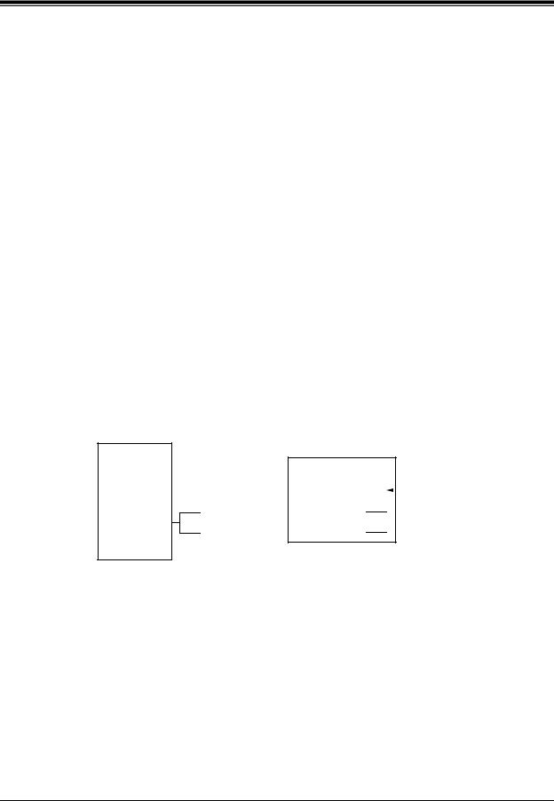
1.4.3Connection Example—APT Integration
For example, you can connect jack 7 of the KX-TA624 to Port 1 of the VPS with a 4-wire connection (see diagram below). This connection creates 1 Voice Mail extension and can only answer 1 call. This means that a fully-configured 2-port system requires 2 jacks from the PBX.
|
|
|
VPS |
|||||
|
|
|
|
|
|
|
|
|
|
|
7 |
|
|
|
|
|
Port 1 |
KX-TA624 |
|
|
|
|
|
|||
|
|
|
|
|
|
Extension 107 |
||
|
|
|
|
|
|
|||
|
|
|
|
|
|
|
|
|
8 
 Port 2
Extension 108
When APT Integration is activated, a single extension jack provides 1 single-line interface at a Port on the VPS. For example, when 1 line cord (4 wire) is connected to Port 1 on the VPS, 1 extension is provided.
Installation Manual |
25 |

VOICE PROCESSING SYSTEM OVERVIEW
1.4.4DPT Integration
To the Panasonic KX-T series PBX that uses DPT Integration, the VPS ports look like digital extensions. The PBX thinks that the VPS is a digital phone, and the VPS mimics all actions of a digital set. Another advantage of digital integration is that the 2B+D communication provides 2 VPS ports for each Digital Station port. Communication between the VPS and the PBX through digital integration requires the proper software level in the PBX and 4-wire connections for each port. To communicate between the VPS and the PBX through DPT Integration, the PBX and VPS must be programmed to work together.
1.4.5Connection Example—DPT Integration
For example, you can connect jack 15 of the KX-TD1232 to Port 1 of the VPS with a 4-wire connection (see diagram below). This connection creates 2 Voice Mail extensions and can simultaneously answer 2 calls. This means that a fully-configured 2-port system requires only 1 jack from the PBX.
VPS
KX-TD1232 |
|
15 |
|
|
|
|
|
|
|
||
|
|
|
|
|
|
|
|
|
|
|
|
Port 1
Extensions 165 and 166
When DPT Integration is activated, a single extension jack provides 2 single-line interfaces at a Port on the VPS. For example, when 1 line cord (4 wire) is connected to Port 1 on the VPS, 2 extensions are provided.
26 |
Installation Manual |

INSTALLATION
Section 2
INSTALLATION
Installation Manual |
27 |

INSTALLATION
2.1SAFETY PRECAUTIONS
Please read the following precautions before installing the VPS.
2.1.1Installation
The VPS needs to be mounted on a wall. Improper placement of the system may result in malfunction, noise, or discoloration. Avoid installing the VPS in the following places:
•in direct sunlight; in hot, cold, or humid places
•in new areas where there are thermal springs, etc. (where sulfuric gas may damage the equipment or contacts).
•where shocks or vibrations are frequent or strong.
•in dusty places or places where water or oil may come in contact with the unit.
•near high frequency generating devices such as sewing machines, elevators or electric welders.
•on or near computers, telexes, or other office equipment; near microwave ovens or air conditioners. (Ideally, the VPS should not be in the room with these items and should be at least 1.8 m {6 feet} away from televisions.)
Do not obstruct the areas around the PBX and the VPS. Both require space above for cooling and space on the sides for maintenance and inspection.
28 |
Installation Manual |

INSTALLATION
2.1.2Wiring
•To assure good quality telephone connection, it is recommended new and modifications to existing installation of customer premise wiring shall use solid twisted pair copper conductors with minimum 24 gauge that comply with the electrical specifications for Category 3 wiring as detailed in ANSI/EIA/TIA-570A Building Wiring Standards.
•Do not wire the telephone cable parallel to an AC power source, computer, etc. If cables are run near those wires, shield them with metal tubing or use shielded cables and ground the shields.
•Use protectors if running cables on the floor. Avoid running cables under carpets.
•Avoid sharing a 120 V AC power supply for computers, telexes, and other office equipment with the VPS. Induction noise from such equipment may interrupt the VPS operation.
When making any connections or removing the cover, be sure the power switch is turned off.
When installing telephone wiring, basic safety precautions should always be followed to reduce the risk of fire, electric shock and injury to persons, including the following:
•Never install telephone wiring during a lightning storm.
•Never install telephone jacks in wet locations unless the jack is specifically designed for wet locations.
•Never touch uninsulated telephone wires or terminals unless the telephone line has been disconnected at the network interface.
•Use caution when installing or modifying telephone lines.
Note
If you live in an area that can have frequent power failures, we strongly recommend that you purchase a suitable UPS (uninterruptible power supply) for your VPS (and PBX if needed). The power rating of your VPS may be found in the specifications.
Installation Manual |
29 |

INSTALLATION
2.2UNPACKING
Unpack the box and check the items below.
Table 5
Main Unit |
1 |
|
|
AC Cord |
1 |
|
|
Screws (Wall Mounting) |
3 |
|
|
Anchor Plugs (Wall Mounting) |
3 |
|
|
30 |
Installation Manual |
Loading...