


Makita GA4543C, GA4541C, GA5041C, GA4041C, GA4043C User Manual
...T |
|
PI / SC / NP |
||
ECHNICAL INFORMATION |
PRODUCT |
|||
|
GA4041C/GA4043C, GA4541C/GA4543C, |
P 1/ 14 |
||
Model No. |
|
|||
|
|
GA5041C/GA5043C |
L |
|
Description Angle Grinders 100mm (4"), 115mm (4-1/2"), |
|
|||
|
|
125mm (5") |
H |
|
CONCEPT AND MAIN APPLICATIONS |
||||
|
||||
1,400W Angle grinder series models; GA4041C/ GA4043C, GA4541C/ GA4543C and GA5041C/ GA5043C are successor models of 9560 series models, featuring:
•"Super Joint System II" developed for effective vibration absorption
•Electronic current limiter, speed control and soft start
•Mechanical brake for powerful braking
•Anti-restart function*1
•Re-designed durable gear housing
•Ergonomically best possible barrel grip
W
Dimensions: mm (")
Model No. |
GA4041C |
|
GA4541C |
|
GA5041C |
GA4043C |
|
GA4543C |
|
GA5043C |
|
|
|
|
|||
Length (L) |
|
325 (12-3/4) |
|
|
|
Width (W) |
117 (4-5/8) |
|
130 (5-1/8) |
|
140 (5-1/2) |
|
|
||||
Height (H) |
117 (4-5/8) |
|
121 (4-3/4) |
||
*1 Anti-restart function is for models, GA4041C, GA4541C, GA5041C only
 Specification
Voltage (V) |
Current (A) |
Cycle (Hz) |
Continuous Rating (W) |
Max. Output (W) |
||
Input |
Output |
|||||
|
|
|
|
|||
110 |
13 |
50/60 |
1,400 |
840 |
1,800 |
|
120 |
12 |
50/60 |
--- |
840 |
2,000 |
|
127 |
12 |
50/60 |
1,400 |
840 |
2,000 |
|
220 |
6.7 |
50/60 |
1,400 |
840 |
2,100 |
|
230 |
6.4 |
50/60 |
1,400 |
840 |
2,100 |
|
240 |
6.1 |
50/60 |
1,400 |
840 |
2,100 |
|
Model No.
Diameter Wheel size: Hole diameter
mm (")
Max. thickness
No load speed: min.ˉ¹=rpm |
|
Shock absorbing system |
|
Electronic |
Constant speed control |
Soft start |
|
|
|
control |
Electronic current limiter |
|
|
|
Anti-restart function |
|
Variable speed control by dial |
GA4041C/ GA4043C |
GA4541C/ GA4543C |
GA5041C/ GA5043C |
100 (4) |
115 (4-1/2) |
125 (5) |
16 (5/8) |
22.23 (7/8) |
|
6 (1/4)
2,800 - 11,000 Super Joint System II Yes
Yes
Yes
GA4041C, GA4541C, GA5041C: Yes/ GA4043C, GA4543C, GA5043C: No
Yes
|
Mechanical brake |
|
|
|
Yes |
|
|
|
Protection against electric shock |
|
|
Double insulation |
|
||
|
Power supply cord: m (ft) |
|
European countries except UK: 4.0 (13.2), Brazil, Australia: 2.0 (6.6) |
||||
|
|
|
Other countries: 2.5 (8.2) |
|
|||
|
|
|
|
|
|||
|
Weight according to |
|
2.6 (5.6) |
|
2.7 (5.9) |
|
2.7 (5.9) |
|
EPTA-Procedure 01/2003*2: kg (") |
|
|
||||
|
|
|
|
|
|
||
|
*2 With Side grip, Wheel cover, Inner flange, Lock nut |
|
|
|
|||
Standard equipment |
|
|
|
|
|
|
|
|
Side grip ............................................... |
|
1 |
|
|
|
|
|
Lock nut wrench .................................. |
|
1 |
|
|
|
|
|
Depressed center wheel ........................ |
|
1 (100mm for GA4041C/ GA4043C, 115mm for GA4541C/ GA4543C, |
||||
|
|
|
125mm for GA5041C/ GA5043C) |
|
|||
|
Note: The standard equipment for the tool shown above may vary by country. |
|
|||||
Optional accessories |
|
|
|
|
|
|
|
|
Depressed center wheels |
Wheel covers for wire cup brush sets |
Abrasive cut off wheels |
|
|||
|
Rubber pads |
Wire bevel brush sets |
Wheel covers |
|
|||
|
Dust collection wheel guards |
Wheel covers for wire bevel brush sets Sanding lock nut |
|
||||
|
Abrasive discs |
Diamond wheels |
etc. |
|
|||
|
Wire cup brush sets |
Dust collecting wheel guards |
|
|
|
||
P 2/ 14
 Repair
CAUTION: Repair the machine in accordance with “Instruction manual” or “Safety instructions”.
[1] NECESSARY REPAIRING TOOLS
Code No. |
Description |
Use for |
|
|
|
1R028 |
Bearing setting pipe 20-12.2 |
mounting Gear housing cover to Armature |
|
|
|
1R045 |
Gear extractor (Large) |
separate Armature from Gear housing cover |
1R232 |
Pipe 30 |
removing Coupling and Ball bearing 6903ZZ from large Spiral bevel gear |
|
|
|
1R258 |
V block |
supporting Armature and Bearing box |
1R268 |
Spring pin extractor M3 |
disassembling Shaft lock mechanism |
|
|
|
1R269 |
Bearing extractor |
removing Ball bearings 627DDW/ 696ZZ from Armature |
|
|
|
1R281 |
Round bar for Arbor 7-50 |
removing Switch knob from Switch lever |
|
|
|
1R286 |
Round bar for Arbor 12-50 |
removing large Spiral bevel gear section from Bearing box |
|
|
|
1R291 |
Retaining ring S & R pliers |
removing Retaining ring S-9 |
|
|
|
1R340 |
Bearing retainer wrench |
removing Bearing retainer 20-33 from Bearing box |
1R350 |
Ring 60 |
supporting Gear housing when disassembling Shaft lock mechanism |
|
|
|
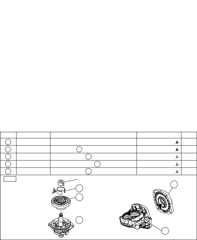
[2] LUBRICATION
Apply Makita grease to the following portions designated with the black triangle and the gray triangle to protect parts and product from unusual abrasion.
Item No. |
Description |
Portion to lubricate |
Lubricant |
Amount |
1 |
Gear housing |
Gear room |
Makita Grease SG No. 0: |
17g |
6 |
Gear housing cover |
O-ring 27.5 of 6 Gear housing cover |
Makita Grease SG No. 0: |
a little |
56 |
C-type plate |
Outer surface where 58 Coupling contacts |
Makita Grease FA No. 2: |
a little |
58 |
Coupling |
Cylindrical portion where 56 C-type plate contacts |
Makita Grease FA No. 2: |
a little |
70 |
Spindle |
Drum portion where 58 Coupling contacts |
Makita Grease FA No. 2: |
a little |
Fig. 1 |
|
Joint sleeve |
6 |
|
|
|
56 |
|
|
|
|
|
|
|
|
|
58 |
|
|


 Spiral bevel gear (large)
Ball bearing 6903ZZ 


 70
70
1
[3] DISASSEMBLY/ASSEMBLY [3] -1. Note in Disassemble (general)
Note: As listed below, the grinders use different spiral bevel gears, and they are not interchangeable. Referring to this list, therefore, be sure to use correct gears for replacement.
Model No. |
No load |
Smaller spiral bevel gear |
Larger spiral bevel gear |
||
speed: min.ˉ¹ |
(on armature shaft) |
(on spindle) |
|||
|
|
||||
GA4041 |
GA4541C |
|
|
|
|
GA4541 |
GA5041C |
11,000 |
10 teeth |
38 teeth |
|
GA5041 |
GA4543C |
||||
GA4041C GA5043C |
|
|
|
||
GA4043C |
|
|
|
|
|
GA6041 |
|
9,000 |
9 teeth |
41 teeth |
|

P 3/ 14
 Repair
[3] DISASSEMBLY/ASSEMBLY
[3] -2. Armature, Spiral bevel gear [small one]
DISASSEMBLING
(1) Remove Spiral bevel gear (small) from the drive end of Armature as drawn in Fig. 2.
Fig. 2
1.Remove Rear cover by unscrewing one 4x18 Tapping screw.
2.Shift Spiral spring from Carbon brush top.
3.Disconnect Carbon brush from commutator by pulling up.
Note: No need to remove Carbon brush in this step.
Rear cover

 4x18 Tapping screw
4.Unscrew four Tapping screws. Then separate Gear housing cover from Spacer while applying a slotted screwdriver to the notch on Gear housing cover on belly side.
Gear housing cover Gear housing |
4x50 Tapping screw |
Gear housing cover |
|
|
|
|
|
Armature |
Notch on
Gear housing cover
Spacer
5.Remove M6 Hex nut to turn it with Wrench 10 counterclockwise. Then, remove Flat washer 6 and small Spiral bevel gear from Armature.
M6 Hex nut
Flat washer 6
Spiral bevel gear (small)


 Wrench 10
6. Remove Gear housing cover with 1R045. Then, remove Compression spring 33 and Brake shoe holder complete.
Caution: Be careful that the cover and the spring may jump out from Armature side
due to recoil force by the spring.
|
Gear housing |
|
1R045 |
cover |
|
Compression |
||
|
||
|
spring 33 |
 Brake shoe

 holder complete


 Armature

P 4/ 14
 Repair
[3] DISASSEMBLY/ASSEMBLY
[3] -2. Armature, Spiral bevel gear [small one] (cont.)
DISASSEMBLING
(2)Disassemble the commutator end of Armature as drawn in Fig. 3.
Note: This step is required for the models with electronic control system of GA4041C, GA4043C, GA4541C, GA4543C, GA5041C, GA5043C.
Fig. 3
1. Pick up three tabs of |
Tabs |
|
Self lock 6 with tweezers |
||
|
||
to remove it from Armature. |
Self lock 6 |
|
|
Tweezers |
2.Remove Magnet sleeve, Wave washer 6 and Labyrinth rubber ring 22.
Magnet sleeve
Wave washer 6
Labyrinth rubber ring 22
3. Remove Ball bearing 627DDW with 1R269. |
4. Remove Flat washer 7 and |
|
Insulation washer. |
1R269 |
Flat washer 7 |
|
|
Ball bearing 627DDW |
Insulation washer |
|
ASSEMBLING
(1) Assemble the commutator end of Armature as drawn in Fig. 4.
Note: This step is required for the models with electronic control system of GA4041C, GA4043C, GA4541C, GA4543C, GA5041C, GA5043C.
Fig. 4
1. Return tabs of Self lock 6 to their |
2. Press down Self lock 6 until |
3. Magnet sleeve is stabilized |
normal shape before assembling. |
Wave washer 6 gets flat. |
between Self lock 6 and |
Then, mount Wave washer 6 to |
|
Wave washer 6 by the reaction |
|
||
the commutator end of Armature. |
|
force of Wave washer 6. |
Note: Be careful of their directions. |
Self lock 6 |
Refer to the drawings in Fig. 4. |
|
|
Magnet sleeve |
Self lock 6 |
|
Magnet sleeve |
|
Wave washer 6 |
Wave washer 6 |
|

P 5/ 14
 Repair
[3] DISASSEMBLY/ASSEMBLY
[3] -2. Armature, Spiral bevel gear [small one] (cont.)
ASSEMBLING
(2) Assemble the drive end of Armature as drawn in Fig. 5.
Fig. 5
1. Set Brake shoe holder |
2. Mount Gear housing cover to |
complete and Compression |
Armature to fit the groove of |
spring 33 to Armature. |
the cover to Compression |
|
spring 33 and Armature shaft |
Compression |
through Ball bearing 6001LLB. |
spring 33 |
Ball bearing |
|
|
Brake shoe |
Groove of Gear |
||
6001LLB |
|||
holder complete |
|
housing cover |
Armature |
Compression |
spring 33 |
3.Supporting Armature section with 2 pcs. of 1R258, press Gear housing cover to Armature section with 1R028.
 1R028
1R028
1R258


4.Set Spiral bevel gear (small) and Flat washer 6 to Armature shaft. Then, secure them with M6 Hex nut.
Flat washer 6 |
M6 Hex nut |
|
|
||
Spiral bevel |
Wrench 10 |
|
gear (small) |
||
|
 Loading...