


 Loading...
96M0994
General Purpose Digital Laser Sensor
LV Series
Instruction Manual
Safety Precautions
 Warning
•This is the product for detecting the target object. Do not use it in the safety circuit such as the human body protection circuit.
•This product does not have the explosion-proof construction Do not use it in the inflammable atmosphere such as atmosphere gas, liquid or dust.
Laser safety precautions
 Warning
•Use of controls or adjustments, or the performance of procedures other than those specified herein, may result in hazardous radiation exposure.
•The LV series product uses a laser diode as a light source.
Specifications of the laser diode change depending on the model. Refer to the tables below.
Sensor head |
LV-H32, H37, H42, H52, H62, H67 |
|
H47, H35, H64, H65, H100, H300 |
|
|
|
|
|
Wavelength |
650 nm |
|
Maximum output |
3 mW |
|
FDA class |
II |
|
IEC class |
2 |
|
 Warning labels
¡IEC CLASS 2
LV-H32 only
¡IEC (French) CLASS 2
LV-H32 only
¡DIN Klasse 2
LV-H32 only
¡Laser CLASS II warning labels(FDA CLASS II)
THIS PRODUCT COMPLIES WITH |
1-3-14,Higashi-Nakajima,Higashi |
21 CFR 1040.10 AND 1040.11 |
-Yodogawa-ku,Osaka,533-8555,JAPAN |
CAUTION |
|
|
CAUTION |
|
LASER RADIATION- |
|
|
LASER RADIATION- |
|
DO NOT STARE INTO BEAM. |
DO NOT STARE INTO BEAM. |
|||
SEMICONDUCTOR LASER |
650nm |
SEMICONDUCTOR LASER |
650nm |
|
MAXIMUM OUTPUT |
3mW |
MAXIMUM OUTPUT |
3mW |
|
PULSE DURATION |
3.5 s |
PULSE DURATION |
3.5 s |
|
CLASS II LASER PRODUCT |
|
|
CLASS II LASER PRODUCT |
|
The FDA warning label has already been stuck.
¡Aperture label
AVOID EXPOSURE
LASER RADIATION IS EMITTED
FROM THIS APERTURE.
¡Protective housing label
CAUTION
LASER RADIATION WHEN OPEN.
DO NOT STARE INTO BEAM.
Safety features
 Laser ON alarm indicator
The laser ON alarm indicator will start flashing after power is turned on. The lamp will remain ON for as long as the laser light is emitting. This alarm indicator can be seen even when wearing protective goggles.
LASER
ON
MODE SET
Laser ON alarm indicator
PH 
 BH
BH 
 %
% 

A 

B 

 Laser emission stop input (LV-21A/21AP/51M/51MP/11A)
Laser emission can be stopped by short-circuiting |
5 V DC |
|
|
between the purple and blue (GND) wires when LV-21A, |
circuit |
|
|
LV-51M or LV-11A used. When LV-21AP or 51MP is used, |
Purple |
||
short-circuit between the purple and brown (12 to 24 V |
Main |
||
|
|||
|
|
||
DC) wires to stop laser emission. |
|
Blue |
|
|
|
||
|
(Short circuit current 1 mA max.) |
||
Label location |
LV-21A/11A/51M |
|
|
|
|
||
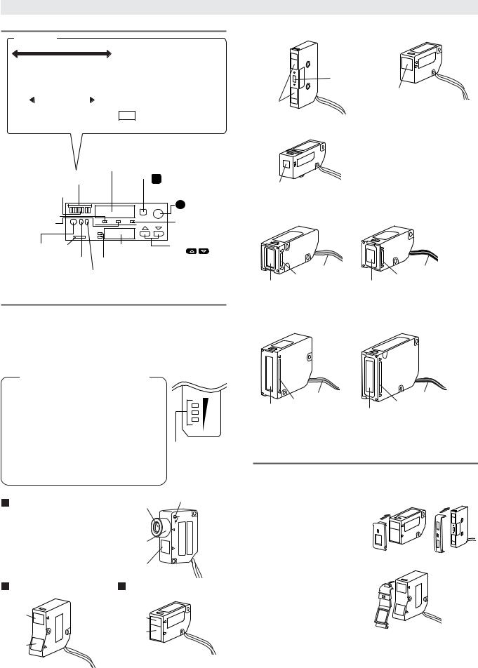
Warning labels are attached to the sensor head, as shown below.
¡LV-H32 |
|
¡LV-H37/H47 |
|
Aperture |
Protect |
Aperture |
|
housing |
|||
|
|
||
|
label |
|
|
|
Aperture |
|
|
|
label |
|
Laser CLASS II warning label
¡LV-H100 (Transmitter side)
Aperture
label  Aperture label
Aperture
Laser CLASS II warning label
¡LV-H42 |
¡LV-H52 |
|
¡LV-H300 (Transmitter side) |
Aperture |
Aperture |
|
|
|
label |
Aperture |
Aperture |
|
|
label |
|
|
|
label |
|
|
|
|
|
|
|
Aperture |
|
|
Laser CLASS II warning label |
|
Aperture |
|
|
|
|
|
|
|
II |
Laser CLASS II warning label
 Warning
Follow the safety precautions below to ensure operator safety:
•Operate the LV Series only according to the procedures described in this instruction manual.
Otherwise, injury may occur due to exposure to the laser beam.
•Do not disassemble the sensor head.
Laser emission from the LV Series is not automatically stopped if the sensor head is disassembled. If you disassemble the sensor head for inspection or repair, you may be exposed to the laser beam. If the LV Series malfunctions, contact KEYENCE immediately.
•Do not look directly at the laser beam.
Looking directly at the laser beam may result in serious eye injury.
•Protective enclosure
It is recommended that you install a protective enclosure around the sensor head to prevent any person from getting near the sensor head during operation.
•Protective goggles
It is recommended that you wear protective goggles when using the LV Series.
•Stop laser emissions before cleaning the laser emission port.
Failure to stop the laser emission may expose eyes or skin to the laser beam.
•Check the laser beam path.
To prevent exposure to the laser beam due to specular or diffuse reflection, install a screen which offers the appropriate reflectance and temperature characteristics to interrupt the reflected laser beam. Do not install the LV Series in such a way that the laser beam passes at eye height.
1
Part Names
Amplifier
Bar LED Monitor
|
|
|
|
|
|
|
|
|
|
|
|
|
|
|
The current value of received light intensity |
|
|
|
|
|
|
|
|
|
|
|
|
|
|
|
is displayed relative to the setting value, |
|
|
|
|
|
|
|
|
|
|
|
|
|
|
|
within the range -15% to +15%. |
|
|
|
|
|
|
|
|
|
|
|
|
|
|
|
Detection is generally stable when the |
15%– 10%– |
|
5%– Setting -5%– -10%– -15%– |
|||||||||||||
|
received light intensity is at least ±10% |
||||||||||||||
|
|
|
|
|
|
value |
|
|
|
|
|||||
|
|
|
|
|
|
|
|
|
|
|
|
|
|
|
different to the setting value, which is |
Light is |
Light is |
|
Light is |
|
Light is |
represented by the center bar of the |
|||||||||
steadily |
irregularly |
|
irregularly |
|
steadily |
LED monitor. |
|||||||||
received |
received |
|
interrupted |
interrupted |
|||||||||||
NOTE The illustration shows an example
of a received light intensity of +5%.
Received light intensity monitor
•Displaying received light intensity
•Displaying excess gain
•Displaying the hold value
Bar LED monitor |
|
M |
MODE button |
Displaying excess gain |
|
• Switching displays |
• Switching channels
Calibration indicator |
|
|
|
• Displaying various settings |
|
|
|
|
SET button |
|
|
|
MODE SET |
S Set up sensitivity |
Peak hold display indicator |
|
|
|
|
Bottom hold |
PH |
BH |
% |
Excess gain |
display indicator |
|
|
|
indicator |
A |
|
|
|
|
|
|
|
|
|
|
B |
|
|
|
|
Output |
|
Setting monitor |
UP/DOWN |
|
Laser ON |
button |
|
• Displaying |
button |
|
alarm |
Output A |
Channel |
setting values |
• Changing |
|
indicator |
• Displaying |
setting values |
|||
indicator |
indicator |
||||
|
• Selecting |
||||
|
|
|
settings |
||
|
|
|
between |
||
|
Output B |
|
|||
|
indicator |
|
various settings |
||
Sensor head
 Bar LED monitor (sensor head)
When A, which is closer to the amplifier, is ON, the monitor displays the excess gain of output A. When B is ON, the monitor displays the excess gain of output B.
Bar Graph LED monitor (Interlocked with amplifier)
Light is steadily |
|
|
|
|
The indicator turns on according |
received |
|
|
|
+10% to the difference between the |
|
|
|
|
|||
Setting value |
|
|
|
|
received light intensity and the |
|
|
|
|
|
setting value. The current level |
Light is steadily |
|
|
|
-10% |
of detection stability can be |
interrupted |
|
|
|
determined from this difference. |
|
Display excess
gain on Bar LED monitor
If detection becomes unstable (light cannot be "steadily received" or "steadily interrupted") due to a change in the surroundings or the target, or for any other reason, readjust the sensitivity.
LV-H32 |
Transmitter |
Focus lock |
|
|
|
Adjust the beam spot size by |
|
L |
turning the focus ring. After |
KC |
O |
|
||
|
|
|
completing the adjustment, fix by |
|
|
turning the focus lock screw. |
Focus ring |
|
|
|
|
|
Receiver |
|
LV-H37/H47 |
LV-H41/H42 |
|
Transmitter |
Transmitter |
|
|
|
|
|
Receiver |
|
Receiver |
|
|
|
LV-H51/H52 |
|
LV-H35/H62/H67 |
Transmitter
Transmitter, Receiver
Receiver
 LV-H64/H65
Transmitter, Receiver
 LV-H100
Transmitter side (T) |
Receiver side (R) |
Gray cable |
Black cable |
Red |
Blue |
Transmitter |
Receiver |
 LV-H300
Transmitter side (T) |
Receiver side (R) |
Gray cable |
Black cable |
|
Red |
Blue |
|
Transmitter |
||
Receiver |
||
|
Slit for sensor head (Option for LV-H41/H42/H47/H51/H52)
Use in accordance with the distance and target.
¡Attaching the slit |
¡LV-H41/H42 |
¡LV-H51/H52 |
Attach the slit to the transmitter |
|
|
¡Removing the slit |
|
|
Remove the slit by lifting up the |
|
|
pin on the slit with a |
|
|
screwdriver. |
|
|
|
¡LV-H47 |
|
2

Accessories
Amplifier
Amplifier |
Mounting bracket |
End unit |
LV-21A/21AP/51M/51MP/ LV-22A/22AP/52/52P
11A only |
only |
Sensor head
 LV-H32
Plastic driver |
Mounting bracket |
|
L |
KC |
O |
Mounting bracket main body Board nut
M3 x 18 screw:2
LV-H35 |
Mounting bracket |
Mounting bracket main body Board nut
M3 x 18 screw:2
 LV-H37
Magnifying glass |
Mounting bracket |
Mounting bracket main body Board nut
M3 x 18 screw:2
 LV-H41/H42
Slit (black, gray) |
Mounting bracket |
Mounting bracket main body Board nut
M3 x 18 screw:2
 LV-H47
Slit (black, gray) |
Mounting bracket |
Mounting bracket main body Board nut
M3 x 18 screw:2
 LV-H51/H52
Slit
LV-H62 |
Reflector |
Mounting bracket |
|
||
|
|
Mounting bracket |
|
|
main body |
|
|
Board nut |
|
|
M3 x 18 screw:2 |
LV-H64/H65 |
Reflector |
Mounting bracket |
|
||
|
|
Mounting bracket |
|
|
main body |
|
|
Board nut |
|
|
M3 x 18 screw:2 |
LV-H67 |
Reflector |
Mounting bracket |
|
||
|
|
Mounting bracket |
|
|
main body |
|
|
Board nut |
|
|
M3 x 18 screw:2 |
 LV-H100
Transmitter side (T) |
Receiver side (R) |
Gray cable |
Black cable |
 LV-H300
Transmitter side (T) Receiver side (R)
Gray cable |
Black cable |
Input/Output Circuit Diagram
¡LV-11A/21A/51M |
¡LV-22A/52 |
|
|
|
Brown |
|
12 to 24 V DC |
|
|
|
Black |
|
|
|
|
|
|
|
|
||
|
|
protectioncircuit |
Black |
|
|
|
|
|
|
|
Overcurrent |
Load |
5 to 40 V DC |
|
|
protectioncircuit |
(Control |
||
circuitMain |
(Control output A) |
circuitMain |
Overcurrent |
output A) |
|||||
White |
|
|
White |
||||||
|
|
|
(Control output B) Load |
5 to 40 V DC |
|
|
|
||
|
|
|
|
|
|
(Control |
|||
|
|
|
|
|
|
|
|
|
|
|
|
|
Purple(Laser radiation interruption input) |
|
|
|
output B) |
||
|
|
|
|
|
|
|
|||
|
|
|
Pink(External tuning input)* |
|
|
|
|
|
|
|
|
|
Blue |
|
0 V DC |
|
|
|
|
|
|
|
|
|
|
|
|
|
|
* LV-51M (monitor output) only is orange.
¡LV-21AP/51MP |
|
¡LV-22AP/52P |
|
||||||
|
|
|
Brown |
12 to 24 V DC |
|
|
12 to 24V DC |
|
|
|
|
protection circuit |
|
|
|
|
|||
|
Overcurrent |
Black |
|
|
|
protection circuit |
|
||
Main circuit |
(Control output A) |
Load |
Main circuit |
Overcurrent |
Black |
||||
|
|||||||||
White |
|
||||||||
|
(Control |
||||||||
(Control output B) |
Load |
||||||||
output A) |
|||||||||
Purple |
|
White |
|||||||
(Laser radiation interruption input) |
|||||||||
|
|
|
|
|
|
(Control |
|||
|
|
|
Pink* |
|
|
|
|
||
|
|
|
|
|
|
|
output B) |
||
|
|
|
(External tuning input) |
|
|
|
|||
|
|
|
Blue |
0 V DC |
|
|
|
|
|
|
|
|
|
|
|
|
|
||
|
|
¡Laser radiation interruption |
|
|
(Main unit only) |
|
|
External tuning input circuit |
Load |
|
|
|
5 to 40 V DC |
diagram |
|
|
Load |
LV-21A/11A/51M |
|
5 to 40 V DC |
|
|
|
5 V DC |
|
|
circuit |
|
|
Main |
Purple or Pink |
|
|
|
|
(Short circuit current |
Blue |
|
1 mA max.) |
|
|
LV-21AP/51MP |
|
|
|
12 to 24 V DC |
|
circuit |
Brown |
Load |
|
|
|
Main |
Purple or Pink |
Load |
|
|
|
|
|
|
(Short circuit current |
|
|
2 mA max.) |
|
* LV-51MP (monitor output) only is orange.
¡Analog output circuit diagram for monitor (LV-51M/51MP)
circuit |
Protection |
Orange |
Output for |
circuit |
|
||
|
(1 to 4 V) |
||
|
|
|
monitor |
Main |
|
Blue |
0 V |
|
|
|
3
Loading...