


 Loading...
96050E
Setup software TM-H1 for the TM-3000 Series
TM-Navigator
User’s Manual
Read this manual before using the system in order to achieve maximum performance.
Keep this manual in a safe place after reading it so that it can be referenced at any time.

Safety Precautions
This manual explains the functions, usage, and configurations for TM-H1 <TM-Navigator>, Setup software for the TM3000 Series. Read this manual carefully before starting to use the software to ensure the optimum performance and full functionality of the <TM-Navigator>. Keep this manual in a safe place for future reference.
Read the TM-3000 Series User's Manual as well as this manual when using the <TM-Navigator>. The controller portion of the TM-3000 Series is referred to as the "controller" in this manual.
Symbols
This manual indicates symbols as follows.
Reference
Provides advanced and useful information for operation.

Contents
Contents
Chapter 1 Getting Started
System Environment ......................................... |
1-2 |
Installing TM-Navigator ..................................... |
1-2 |
Before Installation ........................................ |
1-2 |
Installing TM-Navigator ............................... |
1-3 |
Uninstalling TM-Navigator ........................... |
1-3 |
Starting and Exiting TM-Navigator .................... |
1-4 |
Start ............................................................. |
1-4 |
Exit ............................................................... |
1-6 |
Connecting via USB .......................................... |
1-7 |
Connection Method ..................................... |
1-7 |
Configuring Communication Settings ......... |
1-7 |
Installing the USB Driver ............................. |
1-8 |
Connecting via Ethernet ................................... |
1-9 |
Connecting .................................................. |
1-9 |
Configuring Communication Settings ......... |
1-9 |
Chapter 4 Displaying the Measure-
ment Data
View measurement value .................................. |
4-2 |
Functions and Display ................................. |
4-2 |
View Image ........................................................ |
4-5 |
Functions and Display ................................. |
4-5 |
Functions and Usage of Re-measure |
|
(Ref.Value) ........................................... |
4-10 |
Help:Ref.Value ........................................... |
4-11 |
How to Set Re-measure (Ref.Value) .......... |
4-11 |
Inspection Areas ........................................ |
4-12 |
Data Storage ................................................... |
4-13 |
Functions and Display ............................... |
4-13 |
Image Storage ................................................. |
4-19 |
Functions and Display ............................... |
4-19 |
How to Set Re-measure (Ref.Value) .......... |
4-24 |
Chapter 2 Main Window
Main Window .................................................... |
2-2 |
Part Names and Functions .......................... |
2-2 |
Chapter 3 Operations with the Setting Files
Reading and Saving Setting Files ..................... |
3-2 |
Reading and Saving Program Files ............ |
3-2 |
Reading and Saving Environment |
|
Setting Files ........................................... |
3-3 |
Sending and Receiving Settings ....................... |
3-4 |
Sending All Settings .................................... |
3-4 |
Receiving All Settings ................................. |
3-4 |
Chapter 5 Setting Each Function
Setting Items ...................................................... |
5-2 |
Head Settings .............................................. |
5-3 |
Position Correction ....................................... |
5-9 |
Measurement Settings ............................... |
5-10 |
OUT Settings .............................................. |
5-11 |
Common Settings ...................................... |
5-15 |
Setting List ................................................. |
5-20 |
Environment Settings ....................................... |
5-21 |
Setting Methods ......................................... |
5-21 |
Appendix
USB Communication Failure ............................. |
A-2 |
Excel File ........................................................... |
A-5 |
Excel Transfer Contents of Data Storage .... |
A-5 |
Error Messages ................................................. |
A-6 |
Shortcut Key List ............................................... |
A-9 |
Software License Agreement .......................... |
A-10 |
Index ................................................................ |
A-11 |
96050E |
1 |

Contents
MEMO
2 |
- Setup software TM-H1 TM-Navigator User’s Manual - |

Chapter1
Getting Started
This chapter describes installing or uninstalling the TM-Navigator,
installing the USB driver, and connecting the controller to a computer.
System Environment . . . . . . . . . . . . . . . . . . . . . . . . . . . . . . .1-2
Installing TM-Navigator . . . . . . . . . . . . . . . . . . . . . . . . . . . . .1-2
Starting and Exiting TM-Navigator . . . . . . . . . . . . . . . . . . . .1-4
Connecting via USB. . . . . . . . . . . . . . . . . . . . . . . . . . . . . . . .1-7
Connecting via Ethernet . . . . . . . . . . . . . . . . . . . . . . . . . . . .1-9
Started Getting
- Setup software TM-H1 TM-Navigator User’s Manual - |
1-1 |

Started Getting
System Environment • Installing TM-Navigator
System Environment
The following computer environments are necessary to use the TM-Navigator.
•CPU:
Pentium III 1GHz or more (1.7GHz or more recommended)
•Supported OS: Windows 7*1 Windows Vista*2
Windows XP Professional Edition/Home Edition Windows 2000
•Memory capacity:
512MB or more (1GB or more recommended)
•Display:
XGA (1024 x 768 pixels) or greater, 256 colors or greater
•Hard disk drive space: 1GB or more
•Interface*3:
Includes one of the following: USB2.0/1.1*4 or Ethernet*5
* Use this software in recommended environments according to your OS.
*1 Compatible with each edition of Home Premium, Professional, Ultimate.
*2 Compatible with each edition of Ultimate, Business, Home Premium and Home Basic.
*3 Select one for communication. Multiple interfaces cannot be used for communication at the same time.
*4 Function is not guaranteed when connected through a USB hub.
*5 Function is not guaranteed when connected through a router or a LAN connection.
To use the Excel transmission function, install any of the following applications in addition to the above requirements.
Excel2007 / Excel2003 / Excel2002 / Excel2000
Installing TM-Navigator
This section describes how to install the TM-Navigator and "USB driver" to a computer.
Before Installation
Check the following items before installing.
Reference
•We recommend making a backup of the master disc in case the CD-ROM becomes damaged.
•Close all programs before installing.
User privileges
•For Windows XP/2000
When TM-Navigator is installed into the default folder (C:\Program Files\Keyence\TM-Navigator\), set the following access privileges.
Users must be given rights for “User” or greater in order to use TM-Navigator.
•For Windows VISTA/7
When TM-Navigator is installed into the default folder (C:\Program files\Keyence\TM-Navigator\), set the following access privileges.
Users must be given rights for "User" or greater in order to use TM-Navigator.
Free space on the hard disk
TM-Navigator can only be installed on a hard disk drive. The hard disk drive where the software will be installed must have at least 1GB of free space. If there is insufficient free space, delete unnecessary items to secure the free space.
Pre-installation Windows environment
TM-Navigator is a Windows application and the software is installed in Windows. Check that Windows 7/Vista/XP/ 2000 is installed on the computer and is working properly.
1-2 |
- Setup software TM-H1 TM-Navigator User’s Manual - |

Installing TM-Navigator
Installing TM-Navigator
Reference
Log onto the computer as a user with "Administrator" privileges for installation.
This section explains how to install TM-Navigator using the following drive configuration as an example.
C Drive: Hard drive
EDrive: CD-ROM drive
1 Start up Windows and insert "TM-H1" into the CD-ROM drive.
2Select "Run..." from the Start menu. Enter "e:\set up" into the [File name]
dialog box and click the [OK] button.
3Follow the directions on the installation program for installation.
Reference
•The driver necessary for the USB connection is installed.
•TM-Navigator installation folder
When installing TM-Navigator with the default settings, the program is installed into the following folder:
C:\Program files\Keyence\TM-Navigator\
Uninstalling TM-Navigator
Reference
Log onto the computer as a user with "Administrator" privileges for uninstallation.
1 Select Control Panel for the Start menu.
2 Select Add or Remove Programs.
3Select TM-Navigator from Currently installed programs and click the
Remove button.
[Add or Remove Programs] window appears.
4 Click [Yes].
TM-Navigator is uninstalled from the computer.
Started Getting
- Setup software TM-H1 TM-Navigator User’s Manual - |
1-3 |
Starting and Exiting TM-Navigator
Starting and Exiting TM-Navigator
|
|
|
Getting |
This section describes how to start and exit TM-Navigator. |
|
Started |
||
Reference |
||
|
• Multiple instances of TM-Navigator cannot be started |
|
|
up at the same time. |
|
|
• The USB and Ethernet interfaces on a single controller |
|
|
cannot be used at the same time. |
|
|
• Communication is disabled when the controller is in the |
|
|
"Program mode". |
Start
TM-Navigator starts up in one of the following methods:
• Start up with the default values
• Read from a file
• Read the settings of the connected controller
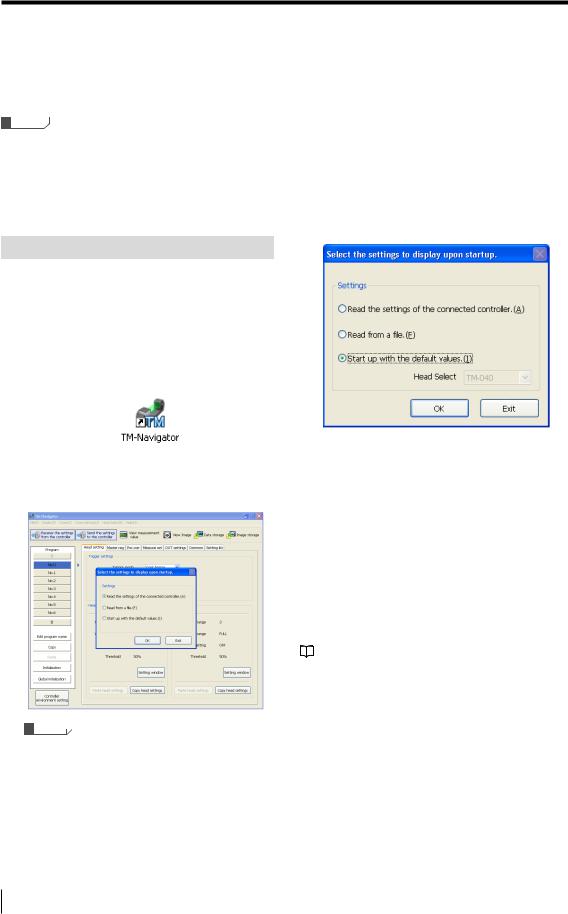
1 Click the [Start] button and then select TM-Navigator, or double-click on the TM-Navigator icon on the desktop.
TM-Navigator starts up. The main screen and the [Select the settings to display upon startup] dialog box are displayed.
Reference
Click the [Exit] button to exit TM-Navigator.
2Select the setting contents and press the [OK] button.
Step 2-1 When [Start up with the default values] is selected
Select [Start up with the default values] the first time that TM-Navigator is started up or when creating a new program.
Use the following procedure to start up.
1Select [Start up with the default values] and click the [OK] button.
TM-Navigator starts up with the default states for all setting files.
The operation when [Start up with the default values] is selected is determined based on whether the head data has been saved on the hard disc drive of the computer or not.
•If not registered (When using TM-Navigator for the first time):
Select the head model to use from the pull-down menu and start up.
•If registered:
The head data already recorded is used at start up. The
head model cannot be selected. "Help:Ref.Value" (page 4-11)
1-4 |
- Setup software TM-H1 TM-Navigator User’s Manual - |
Starting and Exiting TM-Navigator
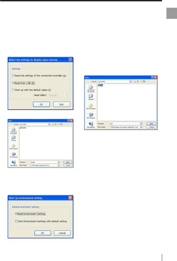
Step 2-2 When [Read from a file] is selected
When [Read from a file] is selected, TM-Navigator loads a program file and an environment setting file that have been saved on the computer.
1Select [Read from a file] and click the [OK] button.
The [Open] dialog box appears.
3Select [Read Environment Setting] or select [Start Environment Settings with
default setting].
The operation procedure will differ depending on the status that [Read Environment Setting] is selected or [Start Environment Settings with default setting] is selected.
(1) When [Read Environment Setting] is selected
Select the environment setting file (*.ens)and click the [Open] button.
The environment setting file is read and TM-Navigator starts up.
(2)[Start Environment Settings with default setting] is selected
TM-Navigator starts up with the defaults for the environment settings.
Started Getting
2 Select a program file to read and click the [Open] button.
The [Start up environment setting (2/2)] dialog appears.
- Setup software TM-H1 TM-Navigator User’s Manual - |
1-5 |
Started Getting
Starting and Exiting TM-Navigator
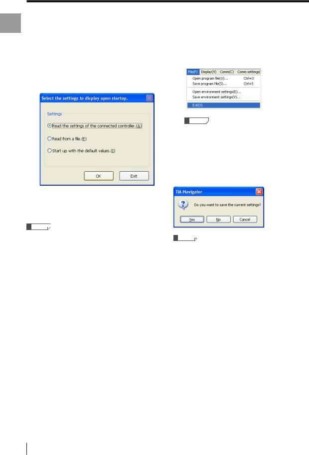
Step 2-3 When [Read the settings of the connected |
Exit |
|
controller] is selected |
||
1 Select [Exit] from the [File] menu. |
||
1 Select [Read the settings of the |
||
connected controller] and click the |
|
|
[OK] button. |
|
The setting files (environment setting file and program file) on the connected controller are read and TM-Navigator starts up.
Reference
In order to read the controller settings, communication must be established between the controller and computer beforehand.
 "Connecting via USB" (page 1-7)
  "Connecting via Ethernet" (page 1-9)
Reference
If the settings have been changed, make sure to save the program file and environment setting file before exiting TM-Navigator. The changes will be lost if the files are not saved before exiting.
 "Reading and Saving Setting Files" (page 3-2)
If the settings have been changed, a confirmation window appears.
Reference
If the [No] button is clicked, TM-Navigator exits without saving the settings.
1-6 |
- Setup software TM-H1 TM-Navigator User’s Manual - |
Connecting via USB
Connecting via USB
This section describes how to connect the controller to a computer with a USB connection.
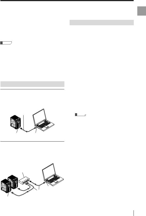
Connection Method
Use a USB cable (included).
Configuring Communication Settings
1 Start up TM-Navigator.
2 Select [PC communication setting] from the [Comm settings] menu.
The [Comm settings] dialog appears.
3Select [Communication via USB] from the [Comm settings] dialog.
Started Getting
USB connector |
USB port |
Reference
•Install the USB driver when connecting the computer
and controller with the USB interface for the first time.
 "Installing the USB Driver" (page 1-8)
•Do not remove the USB cable while the controller is running. Otherwise, the controller may not function correctly. If the communication is disabled due to accidental disconnection of the USB cable, restart both TM-Navigator and the controller.
- Setup software TM-H1 TM-Navigator User’s Manual - |
1-7 |
Started Getting
Connecting via USB
Installing the USB Driver
The driver is installed at the same time as the application software for Windows 7, Vista, XP, and 2000. Normally following operations are not necessary.
If the driver installation is cancelled while installing the application software, follow the procedure below to manually install the USB driver.
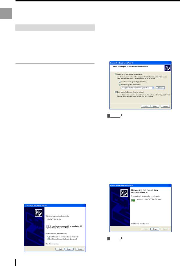
4Select [Search for the best driver in these locations.] and check the box
next to [Include this location in the
search:].
Then, enter "C:\Program Files\KEYENCE\TMNavigator\driver" in the text box and click the [Next] button.
Installing on Windows XP
Connect the controller to a computer with Windows XP. If the controller is being connected for the first time, the USB driver for the TM-3000 Series must be installed. The connection is automatically recognized after the USB driver has been installed once and does not need to be installed again.
This section explains how to install the driver for the TM3000 Series on a computer with Windows XP for the first time.
Hardware detection must be performed when installing the USB driver for the TM-3000 Series.
Use the following methods to install the driver.
1Start up Windows XP and log in as a user that has Administrator privileges
(or similar privileges that permit changing system settings).
2Connect the USB port on the computer with the USB port on the TM-3000
Series controller using the USB cable.
The message "Found New Hardware" appears and the Hardware Update Wizard starts up.
3Select [Install from a list or specific location (Advanced)], and click the
[Next] button.
Reference
"C:\Program Files\KEYENCE\TM-Navigator\driver" represents the location where TM-Navigator will be installed.
Change the location depending on the system environment.
5 Continue installation according to the on-screen instructions.
When installation of the USB driver ends successfully, the [Completing the Hardware Update Wizard] dialog appears.
6Click the [Finish] button to complete installation of the USB driver.
Reference
When installing onto a computer with Windows 2000, install the USB driver according to the wizard.
1-8 |
- Setup software TM-H1 TM-Navigator User’s Manual - |
Connecting via Ethernet
Connecting via Ethernet
This section describes how to connect the controller to a computer with an Ethernet connection. When using Ethernet communication, one computer can be connected to multiple controllers. One of the connected controllers can be selected for communication. The communication protocol is TCP / IP, while the connection uses peer-to-peer communication.
Reference
•Configure the settings so that there are different IP addresses used for the computer and each controller on the network.
•function is not guaranteed when connected through a router or a separate LAN connection.
•One computer cannot communicate with multiple controllers at the same time.
•Multiple computers cannot be connected to one controller.
•Do not set 0.0.0.0 or 255.255.255.255 for the IP address.
Connecting
Connecting one controller directly to one
computer
Use a commercial Ethernet cross cable (*) for connection. * Use cables supporting the communication speed.
Cross cable
Ethernet connector |
Ethernet port |
Connecting to two or more controllers
A 1000BASE-T / 100BASE-TX / 10BASE-T hub is required to connect to two or more controllers. Use commercial Ethernet straight cables to connect between the hub and the computer or controllers.
Hub
Ethernet port
Straight cable
Configuring Communication Settings
Set the following communication settings when communicating with Ethernet.
•IP address
Configure unique addresses for the computer and each controller. Do not set 0.0.0.0 or 255.255.255.255 for the IP address.
Ex.: When using two controllers and one computer
Controller No. 1 |
192.168.0.10 |
Controller No. 2 |
192.168.0.11 |
Computer |
192.168.0.12 |
•Subnet mask
Configure the same settings on the computer and controllers. Use the default value normally.
(Default: 255.255.255.0)
•Default gateway
Use the default value normally. (Default: 0.0.0.0)
1 Set the Ethernet settings for the controller.
Set the IP address, subnet mask, and default gateway.
For more information about configuring settings, see "TM-3000 Series User's Manual".
Reference
Restart all of the controllers after configuring the settings to activate the changes to the Ethernet settings.
2 Set the Ethernet settings (TCP / IP) for the computer.
The method for configuring the settings depends on the version of Windows. For more details, see the instruction manual for the computer or LAN card.
3 Starts up TM-Navigator.
 "Starting and Exiting TM-Navigator" (page 1-4)
4 Select [PC communication setting] from the [Comm settings] menu.
The [Comm settings] dialog appears.
Ethernet connector
Started Getting
- Setup software TM-H1 TM-Navigator User’s Manual - |
1-9 |
Started Getting
Connecting via Ethernet
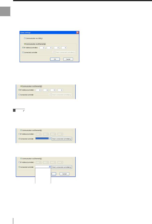
5Select [Communication via Ethernet] from the [Comm settings] dialog.
To enter the IP address for the connected controller directly
Select [IP address (controller)] and enter the IP address for the connected controller.
To search for the connected controller and specify
Reference
Turn the controller on beforehand and check that it is communicating properly.
(1)Select [Connected controller] and click the [Check connected controller] button.
(2)Search for the connected controller automatically. The detected IP address is displayed on the pull-down menu. Then, select the controller for communication.
192.168.0.10
192.168.0.11
192.168.0.13
6 Click the [OK] button.
The [Comm settings] dialog is closed.
1-10 |
- Setup software TM-H1 TM-Navigator User’s Manual - |

Chapter2
Window Main
Main Window
This chapter describes the names and functions of each part of the
TM-Navigator main window and how to operate them.
Main Window . . . . . . . . . . . . . . . . . . . . . . . . . . . . . . . . . . . . .2-2
- Setup software TM-H1 TM-Navigator User’s Manual - |
2-1 |

Window Main
Main Window
Main Window
Part Names and Functions
(1) 
(2)
(3) |
(5) |
(4)
(1)Menu bar
Displays the operational menus for TM-Navigator.
(2)Tool bar
Displays the buttons for frequently used menus, such as the displays for measurement values and communication with the controller.
TM-Navigator reads the setting data (program file and environment setting file) that is saved in the controller.
 "Receiving All Settings" (page 3-4)
TM-Navigator writes changed setting data (program file and environment setting file) to the controller.
 "Sending All Settings" (page 3-4)
Displays the value measured by the head on TM-Navigator.
Clicking [Measurement value acquisition start] button displays and updates the measurement data.
 "View measurement value" (page 4-2)
Displays the image viewed by the head on TM-Navigator.  "View Image" (page 4-5)
2-2 |
- Setup software TM-H1 TM-Navigator User’s Manual - |
Main Window
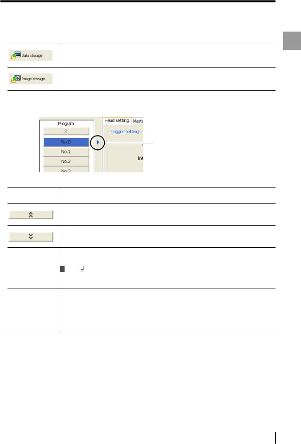
Configures the settings for storing measurement data in the controller.
Stored data can be displayed on TM-Navigator or saved as a file on the computer.  "Data Storage" (page 4-13)
Configures the settings for storing measured image data in the controller.
Stored image data can be displayed on TM-Navigator or saved as a file on the computer.  "Image Storage" (page 4-19)
(3)Setting and operation area for program settings
Switches the program No. of which the setting will be changed.
The currently displayed program
No. is shown.
No. 0 to 15
The settings for the selected program No. can be checked and changed. (Program No.)
Clicking on the selected program No. changes the color of the button to blue.
Clicking on this button displays the preceding program No.
Clicking on this button displays the following program No.
Clicking on this button displays the [Edit program name] dialog. Set the program name in this dialog box.
Edit program name |
Reference |
•Enter up to 16 characters for the program name.
•Letters and numbers can be used for the program name.
Copy |
Copies the settings* in the currently selected program No. for pasting. |
|
Paste |
Pastes the settings* that were copied by using the [Copy] button into the program No. that is |
|
being edited. |
||
|
||
|
|
|
Initialization |
Initializes the settings* in the currently selected program No. |
|
|
|
|
Global initialization |
Initializes the settings* for all of the program No. 0 to 15. |
* "Copy", "Paste", and "Initialization" act on the following settings:
•Head Settings
•Master Registration (including the master image)
•Position Correction
•Measurement Settings
•OUT Settings
•Common Settings
Window Main
- Setup software TM-H1 TM-Navigator User’s Manual - |
2-3 |

Window Main
Main Window
(4)Controller environment setting
Configures settings such as communication conditions for the controller.
 "Environment Settings" (page 5-21)
(5)Program setting area
Sets the measurement conditions for each program. The tabs toggle between each setting.
• Head Settings ................. |
"Head Settings" (page 5-3) |
• Master Registration......... |
"Master registration" (page 5-6) |
• Position Correction.......... |
"Position Correction" (page 5-9) |
• Measurement Settings .... |
"Measurement Settings" (page 5-10) |
• OUT Settings................... |
"OUT Settings" (page 5-11) |
• Common Settings ........... |
"Common Settings" (page 5-15) |
• Setting List ...................... |
"Setting List" (page 5-20) |
Reference
For more information about each setting, see "TM-3000 Series User's Manual".
2-4 |
- Setup software TM-H1 TM-Navigator User’s Manual - |

Chapter3
Operations with the Setting Files
This chapter describes receiving, loading, saving, and sending
setting files.
Reading and Saving Setting Files . . . . . . . . . . . . . . . . . . . .3-2
Sending and Receiving Settings . . . . . . . . . . . . . . . . . . . . .3-4
Files Setting the with Operations
- Setup software TM-H1 TM-Navigator User’s Manual - |
3-1 |
Files Setting the with Operations
Reading and Saving Setting Files
Reading and Saving Setting Files
There are two types of setting files used by TM-Navigator: |
Saving program files |
|
Program files (*.prs) |
||
|
||
Environment setting files (*.ens) |
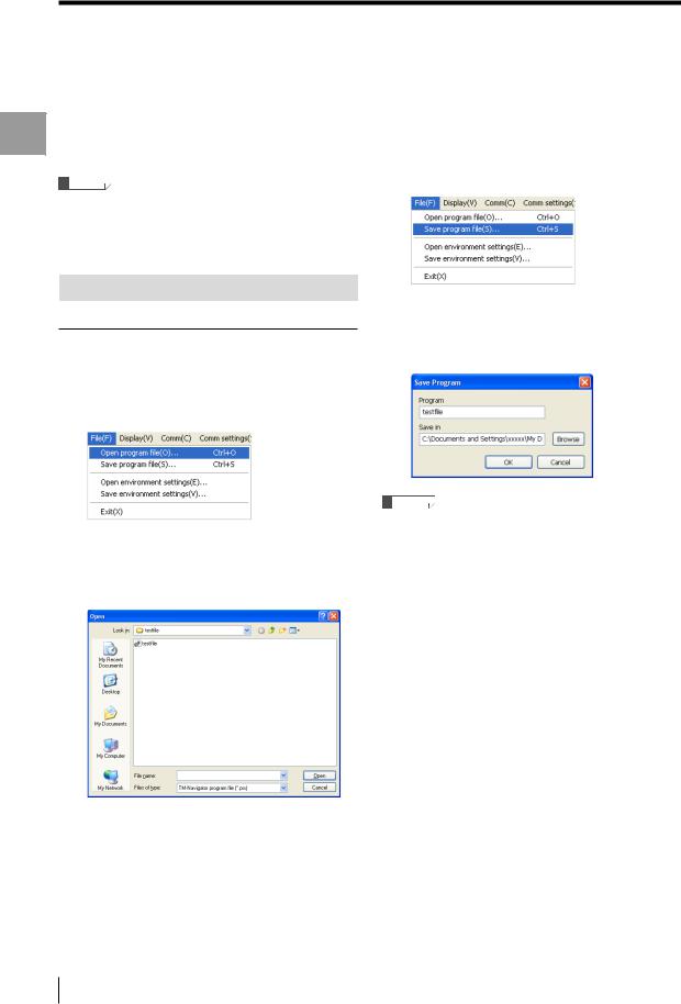
1 Select [Save program file] from the |
|
This section describes how to read setting files from the |
||
computer and save files to the computer. |
[File] menu. |
|
Reference |
The [Save] dialog appears. |
•Program files include all of the settings in program No. 0 to 15.
•Program files and environment setting files are managed separately.
Reading and Saving Program Files
Reading program files
1 Select [Open program file] from the [File] menu.
The [Open] dialog appears.
2 Enter a program name and click on the [Save] button.
The program file is saved.
2 Select a program file (*.prs) to read and click the [Open] button.
The program file is read.
Reference
•If a previously saved program file exists with the same name, the file is overwritten.
•When a master image is registered in the saved program file, the master registration image is saved in the BMP format (extension: .bmp).
3-2 |
- Setup software TM-H1 TM-Navigator User’s Manual - |
Reading and Saving Setting Files
Reading and Saving Environment Setting Files
Reading environment setting files
1 Select [Open environment settings] from the [File] menu.
The [Open] dialog appears.
2Select an environment setting file (*.ens) to read and click the [Open]
button.
The environment setting file is read.
Saving environment setting files |
|
|
1 |
Select [Save environment settings] from |
|
2 |
the [File] menu. |
Settingthe with Operations |
Enter a file name and click on the |
||
|
[Save] button. |
Files |
|
The environment setting file is saved. |
|
Reference
If a previously saved environment setting file exists with the same name, the file is overwritten.
- Setup software TM-H1 TM-Navigator User’s Manual - |
3-3 |
Files Setting the with Operations
Sending and Receiving Settings
Sending and Receiving Settings
This section describes how to transmit all settings between TM-Navigator and the controller.
Settings that are changed in TM-Navigator are updated to the controller immediately after being sent. Settings from the controller are reflected to TM-Navigator immediately after being received.
This function transmits the following data to the controller.
•All of the settings for program No. 0 to 15 (Head settings, Master registration, Position correction, Measurement settings, OUT settings, Common settings)
•Controller environment settings
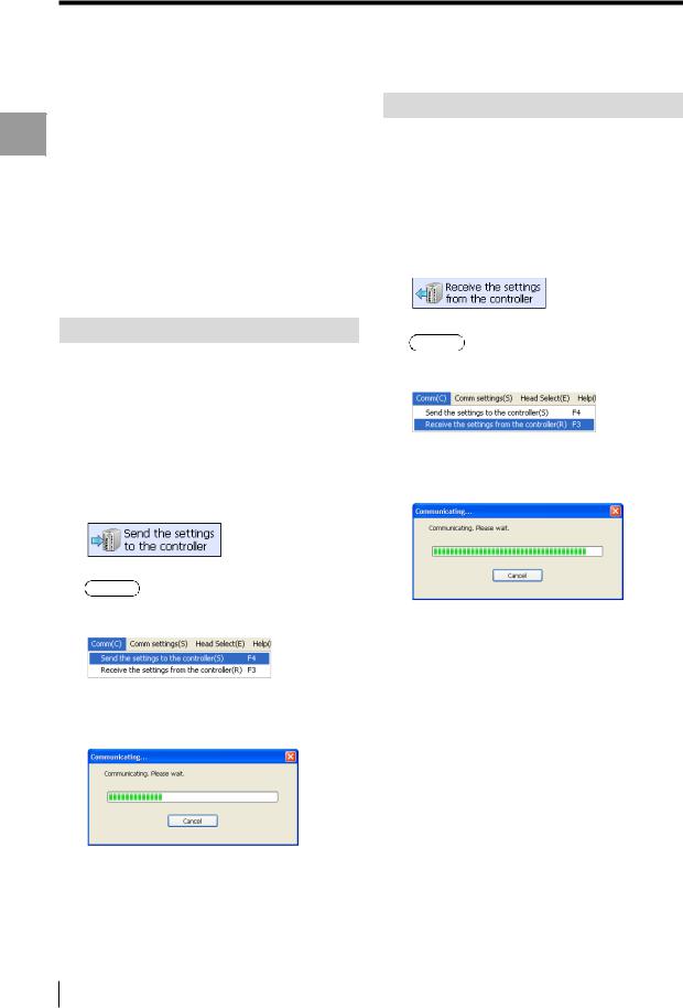
Receiving All Settings
1 Connect TM-Navigator and the controller, and check that communication is normal.
 "Connecting via USB" (page 1-7)
  "Connecting via Ethernet" (page 1-9)
2Click the [Receive settings from controller] icon of the tool bar.
Sending All Settings
1Connect TM-Navigator and the controller, and check that
communication is normal.
 "Connecting via USB" (page 1-7)
  "Connecting via Ethernet" (page 1-9)
2Click the [Send settings to controller] icon on the tool bar.
Alternative
Select [Send the settings to the controller] from the [Comm] menu.
The [Communicating] dialog appears.
The dialog closes when sending the settings is complete.
Alternative
Select [Receive the settings from the controller] from the [Comm] menu.
The [Communicating] dialog appears.
The dialog closes when receiving the settings is complete.
3-4 |
- Setup software TM-H1 TM-Navigator User’s Manual - |

Chapter4
Displaying the Measurement Data
This chapter describes how to display and operate the view
measurement value screen.
View measurement value. . . . . . . . . . . . . . . . . . . . . . . . . . . .4-2 View Image . . . . . . . . . . . . . . . . . . . . . . . . . . . . . . . . . . . . . . .4-5 Data Storage . . . . . . . . . . . . . . . . . . . . . . . . . . . . . . . . . . . . .4-13 Image Storage . . . . . . . . . . . . . . . . . . . . . . . . . . . . . . . . . . .4-19
Data Measurement the Displaying
- Setup software TM-H1 TM-Navigator User’s Manual - |
4-1 |
View measurement value
View measurement value
Data Measurement the Displaying
This section describes displaying the values measured with the controller in real time on the TM-Navigator.
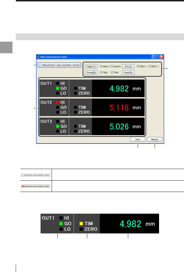
Functions and Display
The values measured by the controller can be displayed in real time in the [View measurement value] window. Measurement controls to the controller such as a trigger and timing input can also be performed.
(1)
(3)
(2)
(4) (5)
(1)[Measurement value acquisition start] button
Displays the values being measured by the controller in real time on TM-Navigator.
Displayed while the measurement value acquisition is stopped. Click this button to start receiving measurement values.
Displayed while the measurement values are being received. Click this button during measurement to stop receiving the values.
(2)View measurement value
Displays the measurement result from the controller for each OUT setting.
The values for all of the OUT settings (OUT1 to OUT16) that are set on the controller are displayed.
Tolerance evaluation output Timing/Zero display |
Measurement value |
4-2 |
- Setup software TM-H1 TM-Navigator User’s Manual - |
View measurement value
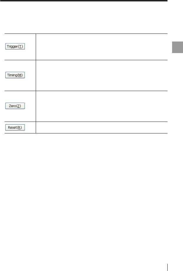
(3) Measurement control
Inputs a control signal into the connected controller.
Inputs a trigger to the specified head.
 : When inputting a trigger to only Head A
 : When inputting a trigger to only Head B
 : When inputting a trigger to both Head A and Head B
Inputs a TIMING input to the specified TIM.
Assign the TIMING input for each OUT setting by using the [Common] tab.  : When inputting TIMING on only TIM1
  : When inputting TIMING on only TIM2
 : When inputting TIMING on both TIM1 and TIM2
Inputs an auto-zero for the specified ZERO.
Assign the ZERO input for each OUT setting by using the [Common] tab.  : When inputting auto-zero on only ZERO1
 : When inputting auto-zero on only ZERO2
 : When inputting auto-zero on both ZERO1 and ZERO2
Resets the measured values that are displayed.
 For more information about each control signal, see "TM-3000 Series User's Manual".
(4)[Close] button
Closes the [View measurement value] window.
(5)[Help] button
Opens the help menu for TM-Navigator.
Data Measurement the Displaying
- Setup software TM-H1 TM-Navigator User’s Manual - |
4-3 |
View measurement value
Data Measurement the Displaying
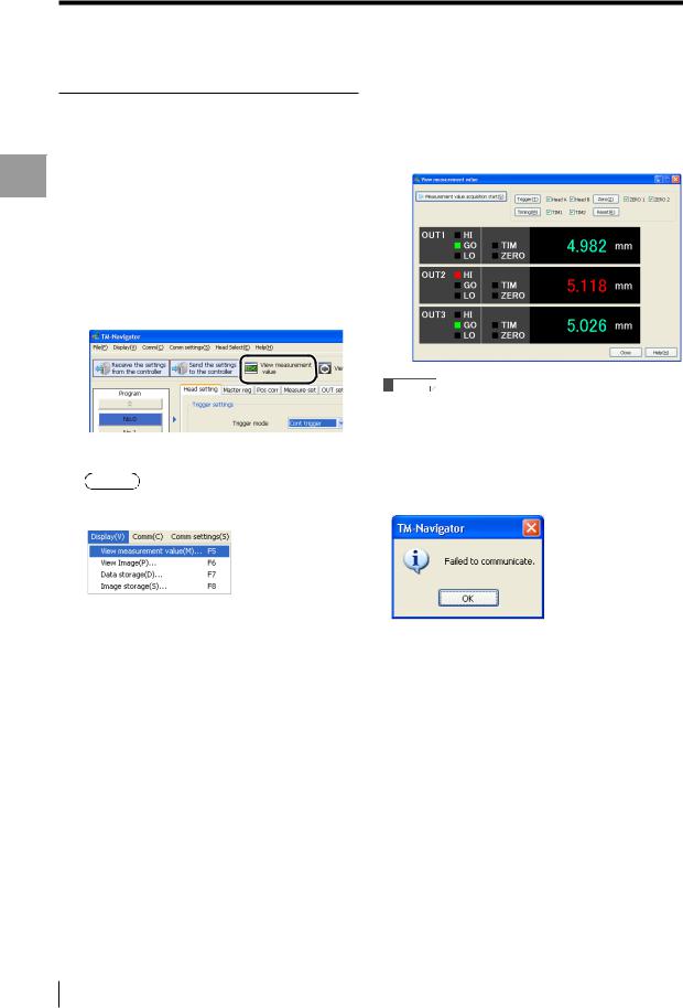
Operating the [View measurement value] window
1Connect TM-Navigator and the controller, check that communication
can be established, and then measure
the target.
 "Connecting via USB" (page 1-7)
  "Connecting via Ethernet" (page 1-9)
2Click the [View measurement value] icon on the tool bar.
The [View measurement value] window appears.
Alternative
•Select [View measurement value] from the [Display] menu.
• Press the "F-5" key.
3 Click the [Measurement value acquisition start] button.
The measurements for the OUT settings that are configured in the controller appear in the window.
Reference
•If communication is not possible between TM-Navigator and the controller, or if a head is not connected, the following dialog appears shortly after clicking the [Measurement value acquisition start] button or [Trigger] button.
Check the connection between each head and between TM-Navigator and the controller.
 For more information about the OUT settings, see "TM-3000 Series User's Manual".
4-4 |
- Setup software TM-H1 TM-Navigator User’s Manual - |
Loading...