


 Loading...
300GB
Fixed Mount 2D Code Reader
SR-750 Series
User's Manual Rev.4.0
Read this manual together with the SR-750 Series Additional Functions Manual.
Read this manual before use.
Keep this manual in a safe place for future reference.
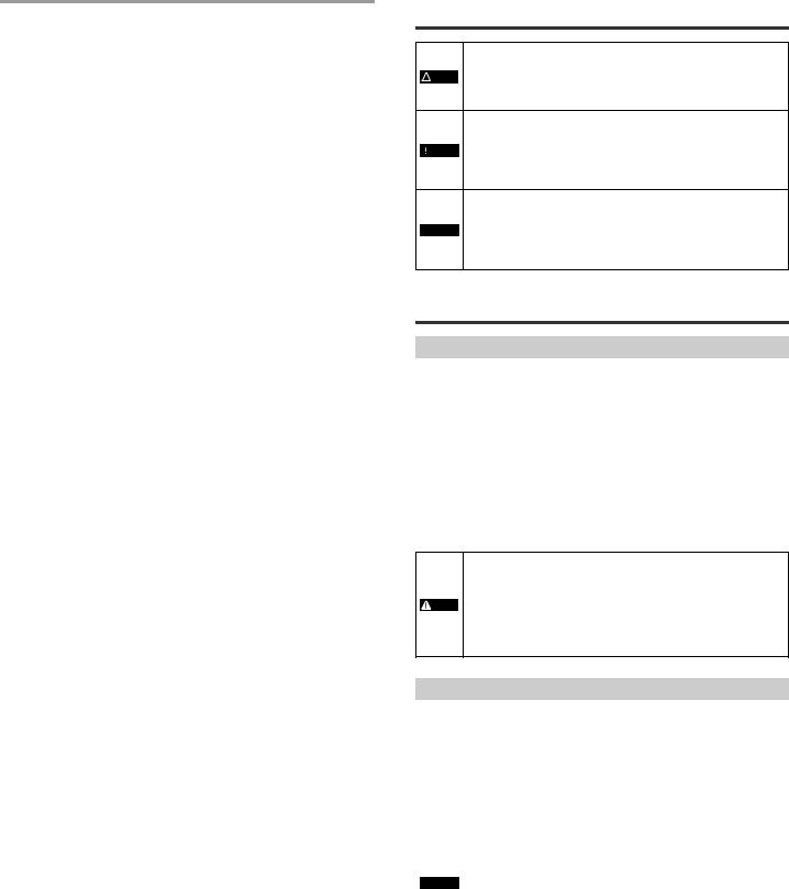
Symbols
This user's manual uses the following symbols that alert you to important messages. Be sure to read these messages carefully.
|
|
|
|
It indicates a hazardous situation which, if not avoided, will result |
|
DANGER |
|||
|
|
|
in death or serious injury. |
|
|
|
|
|
|
|
|
|
|
|
|
|
|
|
It indicates a hazardous situation which, if not avoided, could |
|
WARNING |
|||
|
|
|
result in death or serious injury. |
|
|
|
|
|
|
|
|
|
|
|
|
|
|
|
It indicates a hazardous situation which, if not avoided, could |
|
CAUTION |
|||
|
|
result in minor or moderate injury. |
||
|
|
|||
|
|
|
|
|
|
NOTICE |
|
|
It indicates a situation which, if not avoided, could result in |
|
|
|
product damage as well as property damage. |
|
|
|
|
|
|
|
|
|
|
|
 Important Cautions as to operation that is always performed are shown.
Point |
|
Cautions as to operation that can be easily performed incorrectly |
|
|
|
|
|
are shown. |
|
|
|

 Reference Matters that will help the user improve understanding of the text and useful information are shown.
 The items and pages to be referred to in this document are shown.
Introduction
This instruction manual describes the connection/wiring procedure, setting instructions, and precautions for using the "SR-750 Series 2D Code Reader". Please read this manual thoroughly before using the SR-750 Series to ensure optimum performance. Keep this manual handy for quick future reference.
Table of Contents
|
General Precautions.......................................................................... |
2 |
|
Safety Information for SR-750 Series................................................ |
2 |
|
|
|
1-1 |
Checking the Package Contents ....................................................... |
3 |
1-2 |
Part Names and Functions ................................................................ |
3 |
1-3 |
System Configuration and Setup Flow .............................................. |
4 |
|
|
|
2-1 |
Connecting the Power Source........................................................... |
6 |
2-2 |
Connecting the Control Cable and Wiring ......................................... |
6 |
2-3 |
Connecting the Ethernet Cable ......................................................... |
8 |
|
|
|
3-1 |
Using the SR-750 Series ................................................................... |
9 |
3-2 |
Quick Calibration ............................................................................. |
10 |
3-3 |
Alternate Function ........................................................................... |
11 |
3-4 |
Test Mode........................................................................................ |
12 |
3-5 |
Preset/Verification Function............................................................. |
14 |
3-6 |
Multi-I/O Function ............................................................................ |
14 |
3-7 |
Image Saving Function.................................................................... |
16 |
3-8 |
Silent Mode...................................................................................... |
18 |
3-9 |
SR-600 Compatible Output Mode ................................................... |
19 |
3-10 |
Batch Setting Code.......................................................................... |
20 |
3-11 |
Code quality verification function..................................................... |
20 |
3-12 |
Duplicate reading prevention interval reset ..................................... |
24 |
3-13 |
Edit data function/Edit image file name function.............................. |
24 |
|
|
|
4-1 |
Reading Operations......................................................................... |
26 |
4-2 |
Timing Mode.................................................................................... |
26 |
4-3 |
Data Transmission Timing............................................................... |
27 |
4-4 |
Read Mode...................................................................................... |
28 |
|
|
|
5-1 |
Installing, Starting, and Shutting Down............................................ |
30 |
5-2 |
Screen Layout ................................................................................. |
33 |
5-3 |
AutoID Network Navigator Operation Flow...................................... |
34 |
5-4 |
Details of Settings View................................................................... |
34 |
5-5 |
Sending/Receiving Configuration .................................................... |
49 |
5-6 |
Saving/Reading a Configuration File ............................................... |
49 |
5-7 |
Quick Setup Code ........................................................................... |
50 |
5-8 |
Terminal........................................................................................... |
50 |
5-9 |
LiveView .......................................................................................... |
51 |
5-10 |
ImageView....................................................................................... |
52 |
5-11 |
FileView........................................................................................... |
53 |
5-12 |
Installation Guide............................................................................. |
53 |
5-13 |
Export Reader Configuration ........................................................... |
54 |
5-14 |
Report Generator Function.............................................................. |
55 |
5-15 |
Creating Reports for the SR-750 Series.......................................... |
56 |
|
|
|
6-1 |
Before Mounting the SR-750 Series................................................ |
60 |
6-2 |
Mounting the SR-750 Series ........................................................... |
60 |
6-3 |
Adjusting the Mounting Position ...................................................... |
61 |
6-4 |
Confirming the Reading Stability ..................................................... |
61 |
|
|
|
7-1 |
Communication of the SR-750 Series ............................................. |
63 |
7-2 |
Data Communication Format........................................................... |
63 |
7-3 |
RS-232C Communication................................................................ |
67 |
7-4 |
Ethernet Communication................................................................. |
68 |
7-5 |
Socket Communication.................................................................... |
69 |
7-6 |
FTP Communication........................................................................ |
69 |
|
|
|
8-1 |
Details of Command Communication .............................................. |
71 |
8-2 |
Operation Commands ..................................................................... |
71 |
8-3 |
Details of Configuration Commands................................................ |
75 |
|
|
|
9-1 |
PLC Link .......................................................................................... |
85 |
9-2 |
Configuration ................................................................................... |
85 |
9-3 |
Device Assignment.......................................................................... |
87 |
9-4 |
Reference Program ......................................................................... |
90 |
9-5 |
PLC Link Error................................................................................. |
91 |
|
|
|
10-1 |
Master/Slave function...................................................................... |
92 |
10-2 |
Setting procedure ............................................................................ |
92 |
10-3 Multi drop link mode ........................................................................ |
93 |
|
10-4 |
Multi head mode.............................................................................. |
93 |
1 |
E SR-750 UM |
11-1 |
EtherNet/IP...................................................................................... |
94 |
11-2 |
Cyclic communication...................................................................... |
95 |
11-3 |
Message Communication.............................................................. |
101 |
11-4 |
Reference Program ....................................................................... |
105 |
|
|
|
12-1 |
PROFINET .................................................................................... |
109 |
12-2 |
Cyclic communication.................................................................... |
109 |
|
|
|
13-1 |
Installing MultiMonitor.................................................................... |
112 |
13-2 |
Using MultiMonitor......................................................................... |
113 |
|
|
|
14-1 |
Installing FileView.......................................................................... |
114 |
14-2 |
Using FileView............................................................................... |
115 |
|
|
|
15-1 |
SR-750 Series Specifications........................................................ |
116 |
15-2 |
Dimensions.................................................................................... |
117 |
15-3 SR-750 Series Field of View Size ................................................. |
118 |
|
15-4 |
Troubleshooting............................................................................. |
119 |
15-5 |
Checksum Calculation Method...................................................... |
121 |
15-6 |
ASCII Code List............................................................................. |
121 |
15-7 |
Software License........................................................................... |
122 |
15-8 Precautions on Regulations and Standards .................................. |
122 |
|
15-9 |
Copyright indications ..................................................................... |
123 |
General Precautions
•Do not use this product for the purpose to protect a human body or a part of human body.
 WARNING • This product is not intended for use as explosion-proof product. Do not use this product in a hazardous location and/or
potentially explosive atmosphere.
|
• Be sure to check that the SR-750 Series performs properly |
|
|
before starting the work or operation. |
|
|
• If the SR-750 Series malfunctions, take adequate safety |
|
CAUTION |
||
precautions to prevent various types of damage. |
||
|
•Do not use the SR-750 Series in a manner not specified herein. It may result in fire, electric shock or malfunction.
•It should be noted that functions and performances will not be
guaranteed if the SR-750 Series is used in any way not specified or described in the product specifications or it is modified.
NOTICE • When the SR-750 Series is used in combination with other devices, functions and performance may be degraded, depending on the operating conditions and environment.
Safety Information for SR-750 Series
Safety precautions on Laser product
The SR-750 Series Fixed Mount 2D Code Reader uses a visible semiconductor laser, with a wavelength of 660 nm, as a Laser pointer for adjusting the reading position.
Laser Pointer Specifications
Wavelength |
660nm |
|
Output |
60μW |
|
Pulse duration |
200μs |
|
Laser class |
Class 1 Laser Product |
|
(IEC60825-1, FDA(CDRH) Part 1040.10*) |
||
|
||
|
|
*The classification is based on IEC60825-1 standard following the Laser Notice No. 50 from FDA (CDRH).
•Use of controls or adjustments or performance of procedures other than those specified herein may result in hazardous radiation exposure.
•Do not disassemble this product. The laser radiation emission
WARNING |
from this product is not automatically stopped when it is |
|
|
|
disassembled. |
|
Precautions on Class 1 Laser Product |
|
• Do not stare into the direct or specularly reflected beam. |
Precautions on Proper Use
|
• Do not use a voltage other than that described in the |
|
specifications with the SR-750 Series. Doing so may damage to |
|
the unit. |
|
• The SR-750 Series employs 2 power connection methods, |
|
which are 24 V DC supply and supply from PoE power supply |
|
devices. When connecting the SR-750 Series to the power |
|
source, be sure to use one of these methods. Using both power |
|
sources simultaneously may cause damage to the units. |
|
• Be sure to turn off the power to devices attached to the SR-750 |
|
Series when you plug in or unplug the cables. |
|
Failure to do so may cause damage to the SR-750 Series. |
|
• Do not disassemble or modify the SR-750 Series. Doing so may |
|
damage to the unit. |
NOTICE |
• Place cables as far away as possible from high-voltage lines |
|
and power lines. Otherwise, electrical noise can be generated |
|
that may cause product failure or malfunction. |
|
• The SR-750 Series is a precision instrument. Do not impact or |
|
drop the instrument. Pay particular attention when transporting |
|
or installing the unit. |
|
• Do not hold the unit by its cable when carrying. The units may |
|
become damaged if the cables are disconnected or the units |
|
strike each other. |
|
• Do not allow water, oil, dust, or other foreign substances to |
|
stick to the scanner. This may cause read errors. |
|
Use a soft, dry cloth to wipe any substance from the scanner. |
|
(Do not use a cloth dipped in alcohol or other cleaning |
|
substance.) |
|
|
E SR-750 UM |
2 |
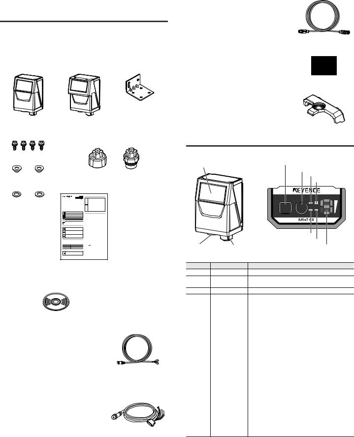
1-1 Checking the Package
Contents
The packages of the SR-750 Series main units and the SR-750 Series configuration software contain the following components.
Check that you have all the package contents before use.
SR-750 Series (Fixed mount 2D code reader)
Main unit |
Mounting bracket x 1 |
SR-750/751/750HA |
SR-752 |
Mounting screw (M4) x 4 Port cover (Power supply and control port, Ethernet connection port) x 1 each
Insulating spacer x 2
Washer x 2 |
Instruction Manual |
Precautions on Proper Use
Fixed Mount 2D Code Reader
SR-750 Series
Instruction manual
Symbols
Precautions on Regulations and Standards
CE Marking
Safety Information for SR-750 Series
General Precautions
CSA Certificate
Safety precautions on Laser product
Laser Pointer Specifications
FDA (CDRH) Regulations
FCC Regulations
IC (Industry Canada) Regulations
1
SR-H3W
AutoID Network Navigator
Cable and connector
Control cable (Power supply, I/O, RS-232C)
•OP-87224 (2 m cable)
•OP-87225 (5 m cable)
•OP-87226 (10 m cable)
NFPA79 compliant Control cable
•OP-87353 (2 m cable)
•OP-87354 (5 m cable)
•OP-87355 (10 m cable)
Control cable (NFPA79-compliant) with D-Sub9 pin (Power supply, I/O, RS-232C)
• OP-87527 (2 m cable)
• OP-87528 (5 m cable)
• OP-87529 (10 m cable)
NFPA79 compliant Ethernet cable
•OP-87359 (2 m cable)
•OP-87360 (5 m cable)
•OP-87361 (10 m cable)
Ethernet assembly plug
• OP-87362
Long distance lens
400 mm lens
• SR-75L4
600 mm lens
• SR-75L6
1-2 Part Names and Functions
This section describes the part names and functions of the SR-750 Series.
(1) Scanner |
(4) TEST button |
|
|
|
(5) TUNE button |
|
(6) POW LED |
|
(7) OK/NG/ERR LED |
|
|
|
OK/NG/ |
STB |
|
|
|
POW ERR |
|
|
|
|
|
|
|
|
|
NET IN |
|
|
|
|
(8) NET LED |
|
|
|
|
(9) IN LED |
|
(2) Power supply and (3) Ethernet port |
(10) Multiple LED indicator |
|
||
control port |
|
|
|
|
Number |
Name |
|
Function |
|
(1) |
Scanner |
Reads 2D codes and bar codes. |
|
|
(2) |
Power supply and |
Connect the control cable. |
|
|
control port |
|
|||
|
|
|
|
|
(3) |
Ethernet port |
Connect the Ethernet cable. |
|
|
|
|
Use this button to perform the following operations: |
||
|
|
• |
Run 1 reading operation. |
|
|
|
• |
Start and stop test mode. |
|
(4) |
TEST button |
• |
Run the multi-reading mode. |
|
|
|
• |
Fix the communication settings of RS-232C to the default |
|
|
|
|
values. |
|
|
|
• |
Reset PLC link error. |
|
|
|
|
||
|
|
Use this button to perform the following operations: |
||
|
|
• |
Turn on the laser pointer for reading position adjustment. |
|
|
|
• |
Start parameter tuning. |
|
(5) |
TUNE button |
• |
Display the number of parameter banks of which the |
|
|
alternate function is effective. |
|||
|
|
|
||
|
|
• |
Read the quick setup code. |
|
|
|
• |
Reset errors. |
|
|
|
• |
Start Ethernet communication BootP mode connection. |
|
|
|
|
||
(6) |
POW LED |
When the power is turned ON, the "green" light turns on. |
||
|
|
|
|
|
|
|
• |
When OK output is ON, the "green" light turns on. |
|
(7) |
OK/NG/ERR LED |
• |
When NG output is ON, the "orange" light turns on. |
|
|
|
• |
When ERR output is ON, the "red" light turns on. |
|
|
|
• |
When connected to Ethernet, the "green" light turns on. |
|
(8) |
NET LED |
• |
When the Ethernet data is sent/received, the "green" light |
|
|
|
|
turns on. |
|
(9) |
IN LED |
When an input terminal is on, this lights up. |
||
|
Multiple LED |
This displays the operation status including the bank |
||
(10) |
number upon successful reading, reading stability and |
|||
indicator |
||||
|
operation mode. |
|||
|
|
|||
300GB |
3 |
E SR-750 UM |

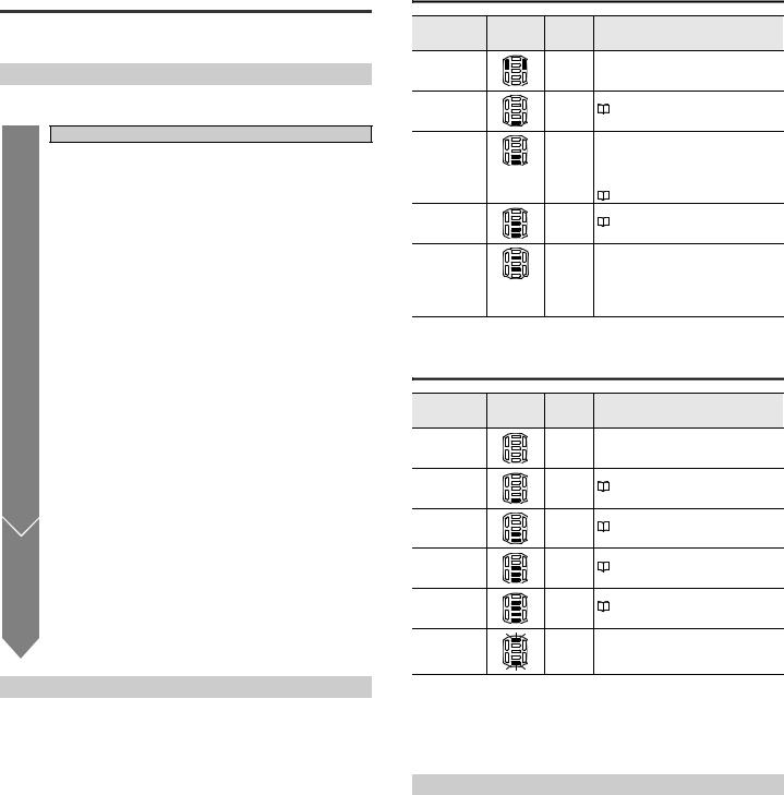
Operation status on the multiple LED indicator
Run mode
In Run mode, the multiple LED displays a number, letter, or other symbol.
Multiple LED |
Display |
Operation |
|
Meaning |
|
indicator |
content |
|
|||
|
|
|
|
||
|
0 to 10 |
When reading |
The parameter bank number is displayed |
||
|
|
successful |
(1 to 10). |
|
|
|
|
|
When the parameter bank is 10, the first |
||
|
|
|
digit value and "1" are displayed alternately. |
||
|
|
|
|
"3-3 Alternate Function (Page 11)" |
|
|
P |
Preset |
Preset successful |
|
|
|
|
|
|
"3-5 Preset/Verification Function |
|
|
|
|
(Page 14)" |
|
|
|
2 points |
Laser pointer |
The laser pointer is turned on when the |
||
|
light up |
emission |
|
button is pressed quickly. |
|
|
2 points |
Set the |
Press and hold the |
button for at least |
|
|
flashing |
communication |
6 seconds. The LED flashes and the RS- |
||
|
|
parameters of the |
232C communication condition returns to |
||
|
|
RS-232C to the |
the factory default state. |
||
|
|
default state. |
|
|
|
|
2 points |
Temporary IP |
Press the TUNE button for at least 5 |
||
|
flashing |
address setting |
seconds. The LED flashes in the |
||
|
|
mode |
temporary IP address setting mode. |
||
|
L |
TUNE button lock |
The |
button is locked according to the |
|
|
|
|
settings. The laser pointer cannot be turned |
||
|
|
|
on and quick calibration cannot be performed. |
||
|
NG |
Saving the read |
The LED lights up while the read error |
||
|
|
error image |
image is being written into the ROM. |
||
|
|
|
|
"3-7 Image Saving Function (Page 16)" |
|
|
E←→ |
Error occurred. |
This shows that an error, such as buffer |
||
|
Error code |
|
over or IP address duplication has |
||
|
|
|
occurred. |
|
|
|
|
|
E and error code (number) lights up |
||
|
|
|
alternately. |
|
|
|
All LEDs |
At power-on |
All LEDs light up for 500 ms when the |
||
|
light up |
|
power is turned on. |
|
|
Quick setup code reading mode
In Quick setup code reading mode, the multiple LED displays a number, alphabet, etc.
Multiple LED |
Display |
Meaning |
|
indicator |
content |
||
|
|||
|
C←→ Numeric |
C: Starts reading the quick setup code. |
|
|
Numeric value: The number "C" of quick setup codes being |
||
|
value |
read and the numeric value are displayed alternately. |
|
|
|
||
|
|
Reading successful or program successful |
|
|
d |
|
Reading failed or program failed
F
Test Mode
In Test mode, the multiple LED displays measurement results.
Multiple LED |
Reading rate |
Processing time |
Position |
OK/NG/ERR |
|
measurement |
|||||
status |
(ms) |
LED |
|||
(%) |
|
||||
|
|
|
|
||
5 bars lit |
|
|
|
|
|
|
90 to 100 |
Up to 99 |
LEVEL 5 |
Green |
|
4 bars lit |
|
|
|
|
|
|
70 to 80 |
100 to 199 |
LEVEL 4 |
Green |
|
3 bars lit |
|
|
|
|
|
|
50 to 60 |
200 to 299 |
LEVEL 3 |
Green |
|
2 bars lit |
|
|
|
|
|
|
30 to 40 |
300 to 399 |
LEVEL 2 |
Green |
|
1 bar lit |
|
|
|
|
|
|
10 to 20 |
400 or more |
LEVEL 1 |
Green |
|
0 bars lit |
|
|
|
|
|
|
|
Reading error |
|
Red |
Other operations
In the quick calibration operation, the multiple LED displays bars, a number, or a letter.
Action |
Multiple LED |
Display content |
Meaning |
|
indicator |
||||
|
|
|
||
|
|
Bar LEDs light up |
This shows the progress of the quick |
|
|
|
calibration. |
||
|
|
in series. |
|
|
|
|
Bar LEDs and |
The quick calibration is complete and the |
|
|
|
test mode is running. Changing the |
||
|
|
upper 2 points |
||
|
|
position of the code fluctuates the bar |
||
|
|
light up. |
||
|
|
LEDs. |
||
|
|
|
||
Quick |
|
|
Quick calibration failed |
|
calibration |
|
F |
(Data for successful quick calibration was |
|
|
|
|
not provided.) |
|
|
|
|
Quick calibration failed |
|
|
|
H |
(Data for successful quick calibration was |
|
|
|
|
provided.) |
|
|
|
|
Saving complete |
|
|
|
d |
|
Error indications on the multiple LED indicator
Display |
Description |
|
content |
||
|
||
E0, E1 |
Main unit system error |
|
* Abnormal operation of the main unit. Contact your nearest KEYENCE office. |
||
|
||
|
|
|
|
Configuration file reading error, image save error |
|
E2 |
* If the operation is not restored even after the main unit is initialized, there may |
|
|
be problems with the main unit . Contact your nearest KEYENCE office. |
|
|
|
|
E3 |
PROFINET error |
|
|
|
|
E4 |
Transmission buffer overflow |
|
|
|
|
E5 |
IP address duplication error |
|
|
|
|
E6 |
Main unit system firmware update error |
|
|
|
|
E7 |
PLC link error |
|
|
|
|
E8 |
Script error |
|
|
|
|
1-3 |
System Configuration and |
|
|
Setup Flow |
System configuration
The SR-750 Series has the following configuration.
SR-750 Series |
|
Setup PC |
|
|
|
Ethernet
AutoID Network
Navigator
Host
PC
Ethernet
EtherNet/IP
PROFINET
PLC
RS-232C
I/O terminal
E SR-750 UM |
4 |
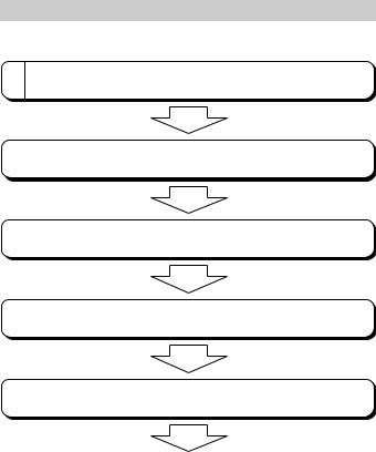
Setup Flow
This section describes the flow of the setup procedure required for starting the operation of the SR-750 Series.
1 After unpacking the package, first check the package contents.
2 |
|
Connect the SR-750 Series to a communication unit or a PC. |
3 |
|
Use the AutoID Network Navigator to configure and send settings to the |
|
||
|
||
|
SR-750 Series. |
|
4 |
|
Install the SR-750 Series according to the location. |
|
||
|
||
5 |
|
Adjust the reading conditions and make the operation settings of the SR- |
|
||
|
||
|
750 Series. |
|
|
|
|
Start operation.
5 |
E SR-750 UM |
2-1 Connecting the Power
Source
This section describes how to connect the SR-750 Series and the power source.
Power supply to the SR-750 Series
There are 2 methods employed for connecting power source to the SR-750 Series.
•Connect the power supply wire of the control cable to a 24 V DC power supply device.
•Connect to a PoE (Power over Ethernet) power supply device using the Ethernet port.
Use only one of the above methods to connect to the power source according to the usage.
Make sure to use either one of the connection methods for power supply.
NOTICE If power is supplied both from the control cable and PoE power supply device at the same time, the unit may be damaged.
Wiring when supplying 24 V to the control cable
|
|
|
|
|
|
|
|
|
|
|
|
|
|
+24 V |
Brown |
|
|
|
|
||
|
|
|
|
|
|
+ |
24 V DC ±10% |
|||
|
|
|
|
|
|
|
|
|
|
|
|
|
|
|
|
|
|
|
|
|
|
|
|
|
|
|
|
|
|
|
|
|
|
|
|
0 V |
Blue |
|
|
|
|
||
|
|
|
|
|
|
|
||||
|
|
|
|
|
|
|
|
|
|
|
|
|
|
|
|
|
|
|
|
|
|
|
|
• Use a steady power supply voltage of 24 V DC ±10%. |
||||||||
|
|
• Do not use a power supply other than 24 V DC. Otherwise, it |
||||||||
NOTICE |
may cause failure. |
|
|
|
|
|||||
• Before connecting or disconnecting cables, make sure to turn |
||||||||||
|
|
|||||||||
|
|
off power to the equipment connected to the SR-750 Series. |
||||||||
|
|
Otherwise, it may cause the failure of the SR-750 Series. |
||||||||
|
|
|
|
|
|
|
|
|
|
|
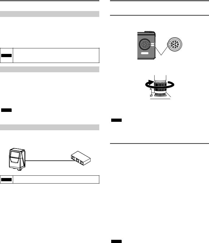
Connection when supplying power from a PoE device
Use the Ethernet cable for the SR-750 Series for connection. Connect the RJ-45 connector of the Ethernet cable to a device (switching hub, etc.) compatible with the PoE power supply feature.
SR-750 Series |
HUB compatible with PoE power supply |
Ethernet cable for the
SR-750 Series
NOTICE |
Be sure to connect with a PoE power supply device compliant |
|
with IEEE802.3af. |
||
|
2-2 Connecting the Control
Cable and Wiring
Connect the control cable to the SR-750 Series.
Control cable connection method
1 Align the dent of the cable connector with the marking position next to the control port.
POWER
Align the notch with the marking position.
2 Tighten the connector screw by turning clockwise. Set the screw tightening torque to 1.5 - 2.0 N•m.
|
When connecting the connector, insert it not to lean toward one |
|
side and securely tighten it. Under-tightening can lead to loose |
|
connector due to vibrations, resulting in poor contact. |
|
Insufficient tightening may not meet the requirements of the |
NOTICE |
protective structure. |
|
* To get a rough idea, after tightening it by hand, retighten it |
|
approximately 90° - 120° using a tool such as pliers. |
|
Do not repeatedly bend the root of the connector of control cable. |
|
Loose connection may result. |
|
|
Control cable color and the meaning of signal
The following different color lead wires are drawn out of the control cable. Solder the lead wire to the connector using the wire attached to the device to be connected.
Wire color |
Symbol |
Description |
Signal |
AWG size |
|
direction |
|||||
|
|
|
|
||
Brown |
24 V |
+24 V power |
Input |
26 |
|
supply |
|||||
|
|
|
|
||
|
|
|
|
|
|
Blue |
0 V |
Power supply |
– |
26 |
|
GND |
|||||
|
|
|
|
||
|
|
|
|
|
|
Orange |
RXD |
RS-232C |
Input |
28 |
|
Receive |
|||||
|
|
|
|
||
Yellow |
TXD |
RS-232C Send |
Output |
28 |
|
|
|
|
|
|
|
Purple |
SGND |
RS-232C GND |
– |
28 |
|
|
|
|
|
|
|
Green |
IN1 |
IN1 Input |
Input |
26 |
|
Gray |
IN2 |
IN2 Input |
Input |
28 |
|
|
|
|
|
|
|
White and blue |
INCOM |
Input common |
– |
28 |
|
mode voltage |
|||||
|
|
|
|
||
|
|
|
|
|
|
Pink |
OUT1 |
OUT1 Output |
Output |
28 |
|
|
|
|
|
|
|
Aqua blue |
OUT2 |
OUT2 Output |
Output |
28 |
|
White |
OUT3 |
OUT3 Output |
Output |
28 |
|
|
|
|
|
|
|
|
|
Output |
|
|
|
Black |
OUTCOM |
common mode |
– |
28 |
|
|
|
voltage |
|
|
|
Black tube |
FG |
FG |
– |
– |
|
|
|
|
|
|
NOTICE |
Make sure to turn the power off when attaching or removing the |
|
control cable. |
||
|
||
|
|
E SR-750 UM |
6 |
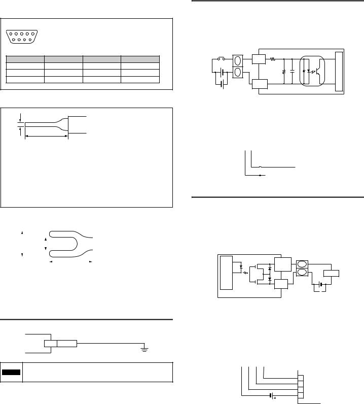
Control cable (NFPA79-compliant) with D-Sub9 pin
z RS-232C wire
The tip of the RS-232C wire is a D-sub9-pin.
5 4 3 2 1 |
D-sub9 pin (Female) |
|
|
|||
|
|
|
|
DTE specifications (Terminal definition) |
|
|
|
|
|
|
M2.6 screw |
|
|
9 |
8 |
7 |
6 |
|
|
|
|
Pin No. |
Symbol |
Description |
Signal direction |
||
|
|
2 |
|
TXD |
Data Send |
Output |
|
|
3 |
|
RXD |
Data Receive |
Input |
|
|
5 |
|
SGND |
Signal GND |
- |
z Control wire (Input/Output signal wire)
The tip of the control wire is a rod terminal.
1 mm
10 mm
Wire color |
Symbol |
Description |
Green |
IN1 |
IN1 Input |
|
|
|
Gray |
IN2 |
IN2 Input |
|
|
|
White and blue |
INCOM |
Input common |
|
|
|
Pink |
OUT1 |
OUT1 Output |
|
|
|
Aqua blue |
OUT2 |
OUT2 Output |
|
|
|
White |
OUT3 |
OUT3 Output |
|
|
|
Black |
OUTCOM |
Output common |
z Power wire
The tip of the power wire is a Y-shape terminal.
|
|
|
|
|
|
|
|
|
|
|
|
|
|
|
|
|
|
|
|
|
|
|
|
|
|
|
|
|
6.6 mm |
|
4.3 mm |
|
|
|
|
|
|
|
|
|
|
|
|
|
|
|
|
|
|
|
|
|
|
|
|
|
|
|
|
|
|
|
|
|
|
|
|
|
|
|
|
|
|
|
|
|
|
|
|
|
|
|
|
|
|
|
|
|
|
|
|
|
|
|
|
|
|
|
|
|
|
|
|
|
|
|
|
|
|
|
|
|
|
|
|
|
|
|
|
|
|
|
|
|
|
|
|
|
|
|
|
|
|
11 mm |
|
|
|
|
|
|
|
|
|
|
|
|
|
|
|
|
|
|
|
|
|
|
|
|
|
|
|
|
|
|
|
|
|
|
Wire color |
|
|
|
Symbol |
|
|
|
Description |
|
|||
|
|
Brown |
|
|
|
24 V |
|
|
+24 V Power supply |
|
|||
|
|
|
|
|
|
|
|
|
|
|
|
|
|
|
|
Blue |
|
|
|
0 V |
|
|
Power supply GND |
|
|||
|
|
|
|
|
|
|
|
|
|
|
|
|
|
|
Black tube |
|
|
|
FG |
|
|
|
FG |
|
|||
|
|
|
|
|
|
|
|
|
|
|
|
|
|
|
|
|
|
|
|
|
|
|
|
|
|
|
|
Connecting the FG wire
Be sure to provide Class D ground for the FG wire.
FG Black tube
The shield and FG wire of the control cable and the shield of the
NOTICE Ethernet cable are electrically connected via the main unit case. Provide them with a common ground.
IN1/IN2 wire connection
•The IN1 (timing) input means the input that causes the SR-750 Series to start reading.
•The IN2 (preset) input means the input that causes the SR-750 Series to register preset data.
IN1/IN2 inputs operate by voltage inputs.
Contact |
|
|
|
or |
|
|
|
non-contact |
10kΩ |
Photocoupler isolation |
|
IN1 (Green) |
|||
Internal |
|||
+ |
|
||
IN2 (Gray) |
|
|
|
|
5.6kΩ |
circuit |
|
INCOM |
|
||
(White and blue) |
|
|
• |
Input rating |
: |
15 - 26.4 V DC |
• |
Repetitive peak off-state current : |
0.2 mA |
|
Connecting a photoelectric sensor manufactured by KEYENCE
Connection example when the IN1 terminal is used as the trigger input terminal.
INCOM |
IN1 |
|
|
|
|
||||
(Whiteandblue) |
(Green) |
|
Photoelectric Sensor (NPN) |
||||||
|
|
|
|
|
|
|
|
|
|
|
|
|
|
|
|
|
|
Brown (red) |
|
|
|
|
|
|
|
|
|
Black (white) |
|
|
|
|
|
|
|
|
|
Blue (black) |
|
|
|
|
|
|
|
|
|
|
|
Connecting the OUT1/OUT2/OUT3 wires
•The OUT1 (OK) output is used as an output for successful reading and verification of OK as a result of checking against the preset data.
•The OUT2 (NG/ERROR) output is used as an output for reading failure and verification of NG reading as a result of checking against the preset data.
•OUT3 (BUSY) is output any time the trigger input cannot be accepted. For example, a busy signal will be output at initial start-up, during the key operation,
reading operation, etc.
The output form of each signal is photo MOS relay.
Internal |
OUT1(Pink), |
|
OUT2(Aquablue), |
|
|
|
|
|
|
OUT3(White) |
|
circuit |
|
Load |
OUT COM |
+ |
|
|
(Black) |
|
|
|
|
|
|
|
|
|
• Maximum rated load |
: 30 V DC (1 output maximum 50 mA, 3 outputs |
||
|
total 100 mA or less) |
||
•Leakage current when OFF : 0.1 mA or less
•Residual voltage when ON : 1 V or less
Connection with KEYENCE PLC (Programmable controller)
OUT |
OUT |
OUT |
OUT |
COM |
1 |
2(Aqua |
3 |
(Black) |
(Pink) |
blue) |
(White) |
PLC
 0002
0002
 0001
0001
 0000
0000
 C
C
7 |
E SR-750 UM |
Wiring the RS-232C signal line
Connect to host devices (PC, PLC, etc.) as illustrated below:
Connection to a PC
PC |
|
RxD |
2 |
TxD |
3 |
GND(SG) |
5 |
RTS |
7 |
CTS |
8 |
DTR(ER) |
4 |
DSR(DR) |
6 |
D-Sub 9 pin |
|
(female) |
|
#4-40 screw |
|
SR-750 Series
Yellow TxD
Orange RxD
Purple SGND
Connection to the handheld programmer for the KEYENCE KV Series
Handheld programmer |
SR-750 Series |
||||
|
|
|
|
|
|
RD |
|
3 |
|
Yellow |
TxD |
|
|
||||
SD |
|
5 |
|
Orange |
RxD |
|
|
||||
SG |
|
4 |
|
Purple |
SGND |
|
|
||||
|
Modular |
|
|
||
Connector
Connection to the KV-L21V/L20V/L20R/N10L
KV-L20V/L20R (Port 1) |
SR-750 Series |
KV-L20V/L20R (Port 2) |
||||||||||
|
|
KV-N10L |
|
|
|
|
|
|
||||
|
|
|
|
|
|
|
|
|
|
|
|
|
RD |
2 |
|
|
|
|
Yellow |
TxD |
SD |
3 |
|
||
SD |
|
3 |
|
|
|
|
Orange |
RxD |
RD |
|
5 |
|
|
|
|
|
|||||||||
RS |
|
7 |
|
|
|
|
Purple |
SGND |
SG |
1 |
|
|
CS |
8 |
|
|
|
|
|
|
|
|
|
|
|
ER |
4 |
|
|
|
|
|
|
|
|
|
|
|
DR |
|
6 |
|
|
|
|
|
|
|
|
|
|
SG |
5 |
|
|
|
|
|
|
|
|
|
|
|
|
|
|
|
|
|
|
|
|
|
|||
D-Sub 9 pin (female)
#4-40 screw
Connection to the QJ71C24N/-R2
QJ71C24N/-R2 |
|
SR-750 Series |
|||||
|
|
|
|
|
|
|
|
RD |
2 |
|
|
|
Yellow |
TxD |
|
|
|
|
|||||
SD |
|
3 |
|
|
|
Orange |
RxD |
|
|
|
|||||
RS |
7 |
|
|
|
Purple |
SGND |
|
|
|
|
|||||
CS |
8 |
|
|
|
|
|
|
|
|
|
|
|
|||
ER |
4 |
|
|
|
|
|
|
|
|
|
|
|
|||
DR |
|
6 |
|
|
|
|
|
|
|
|
|
|
|||
SG |
|
5 |
|
|
|
|
|
|
|
|
|
|
|||
CD |
1 |
|
|
|
|
|
|
|
|
|
|
|
|||
D-Sub 9 pin (male)
M2.6 screw
Connection to the SYSMAC Series PLC
CJ1W-SCU (-V1)
CS1W-SCU -V1
CS1W-SCB -V1
CP1W-CIF01
|
|
PLC |
|
|
|
SR-750 Series |
|
|
|
|
|
|
|
|
|
SD |
|
2 |
|
|
|
Yellow |
TxD |
RD |
|
3 |
|
|
|
Orange |
RxD |
RS |
|
4 |
|
|
|
Purple |
SGND |
|
|
|
|||||
CS |
5 |
|
|
|
|
|
|
|
|
|
|
|
|||
SG |
9 |
|
|
|
|
|
|
|
|
|
|
|
|||
D-Sub 9 pin (male)
M2.6 screw
Wiring with the N-R4 Series
N-R4 |
|
|
SR-750 Series |
||
|
|
|
|
|
|
RD |
3 |
|
|
Yellow |
TxD |
|
|
||||
RS |
4 |
|
|
Orange |
RxD |
|
|
||||
SD |
7 |
|
|
Purple |
SGND |
CS |
8 |
|
|
|
|
|
|
|
|
||
GND |
12 |
|
|
|
|
Round connector 12-pin (male)
SR-750 Series
Yellow TxD
Orange RxD
Purple SGND
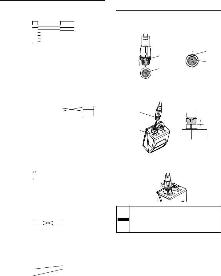
2-3 Connecting the Ethernet
Cable
Connect the Ethernet cable to the SR-750 Series in the following procedure.
1 Preparation of Ethernet cable
First, rotate the connector screw and align the protrusion position with the positioning pin position in the connector.
|
View from the connector side |
|
protrusion |
|
protrusion |
connector screw |
positioning pin |
|
|
|
positioning pin |
|
Rotate the connector screw so that the |
|
protrusion and the positioning pin come |
|
to the above position. |
2 Connect to the SR-750 main unit
Align the protrusion position of the connector screw with the white mark position of the SR-750 Series Ethernet port. Then, insert straight to avoid tilting the connector.
protrusion
Approx. 4 mm
white mark
POWER
ETHERNET
Approx. 4 mm of clearance remains when inserted fully.
3 Tighten the connector
Rotate the connector screw in the arrow direction until it stops (approx. 180 degrees) and tighten it.
|
POWER |
|
ETHERNET |
|
• When connecting the connector, insert it straight so it does not |
|
tilt. Otherwise, the connector pin may be damaged. |
|
• Tighten the connector screw correctly. If it is not tightened |
NOTICE |
properly, the connector may become loose due to vibration, etc. |
|
and connection failure may occur. |
|
• Do not repeatedly bend the root of the connector of Ethernet |
|
cable. Loose connection may result. |
E SR-750 UM |
8 |
3-1 Using the SR-750 Series
This section describes basic uses for performing reading operation using the SR750 Series.
Basic steps
Before using the SR-750 Series, register codes and conduct read test by performing the following steps:
(1) Read condition setting
Perform the quick calibration on the SR-750 Series.
• 3-2 Quick Calibration
• 5-4 Details of Settings View
|
(2) Read test |
|
Once the quick tuning is complete, confirm that reading is stable. |
|
Using the test mode of the SR-750 Series, confirm the reading |
|
stability and the read processing time. |
|
• 3-1 Using the SR-750 Series (TEST Button Operation). |
|
• 3-4 Test Mode |
|
• 5-8 Terminal |
|
|
Preparations |
(3) Determination of operation |
Function leading to stable read |
|
|
Let's consider the usage of the SR-750 Series. |
|
The SR-750 Series has functions that lead to stable operation or |
|
reduction in control man-hours. |
|
• 3-3 Alternate Function |
|
• SR-750 Series Operations |
|
Function leading to reduction in control man-hours |
|
• 3-5 Preset/Verification Function |
|
• 3-6 Multi-I/O Function |
|
• 3-8 Silent Mode |
|
• Edit data function and edit image file name function |
|
• Duplicate reading prevention interval reset |
|
• Master/Slave function |
|
Connection method with a control device |
|
• Connection and Wiring |
|
• SR-750 Series Communication Specifications |
|
|
|
(4) Start of Operation |
|
Once the operation procedure and installation conditions have been |
|
determined, you can start the operation. |
Startof Operation |
The SR-750 Series has the functions that are useful for analyzing |
read errors, etc. that occur during operation. |
|
• 3-7 Image Saving Function |
|
|
• Matching function |
|
• 3-11 Code quality verification function |
|
• 7-2 Data Communication Format |
|
• 7-6 FTP Communication |
SR-750 Main Unit Buttons
The SR-750 Series main unit has 2 buttons for registering and adjusting the reading operation.
• TUNE button : used for turning on the laser-aimer, starting quick calibration and reading the quick setup code
• TEST button : used for starting the test mode and changing the RS-232C communication settings to the default condition.
According to the operating status of each button, the status is also displayed on the multiple LED.
This section describes the operation procedure of the 2 buttons.
TUNE Button Operation Procedure
|
Multiple |
|
|
Operation |
LED |
Lighting |
Action |
|
indicator |
|
|
Press once |
|
|
The laser pointer emits a laser beam. |
quickly |
|
- |
(Reading is disabled while the laser pointer is |
(less than 1 s) |
|
|
on.) |
Press for 2 |
|
Illuminates |
Activates the quick calibration function. |
seconds |
|
1 time |
"3-2 Quick Calibration (Page 10)" |
|
|
|
|
Press for 3 |
|
|
The number of parameter banks (0 to 10) for |
seconds |
|
|
which the alternate function can be used is |
|
|
Illuminates |
shown on the multiple LED indicator. When the |
|
|
2 times |
number of registered parameter banks is 10, "0" |
|
|
|
and "1" are displayed alternately. |
|
|
|
"3-3 Alternate Function (Page 11)" |
Press for 4 |
|
Illuminates |
Activates the batch setting reading mode. |
seconds |
|
3 times |
"3-10 Batch Setting Code (Page 20)" |
|
|
|
|
Press for 5 |
|
|
Activates the temporary IP address setting |
seconds |
|
|
mode. |
|
|
Illuminates |
* Only in this mode, the operation does not |
|
|
3 times |
finish even if the TUNE button is briefly |
|
|
|
pressed once. Assign the temporary IP |
|
|
|
address or turn the power on again. |
*To quit an action/mode, press the  button once briefly.
To quit the quick calibration, hold down the  button for at least 2 seconds.
TEST Button Operation Procedure
|
Multiple |
|
|
Operation |
LED |
Lighting |
Action |
|
indicator |
|
|
Press once |
|
|
One reading operation is performed. |
quickly |
|
Illuminates |
|
(less than 1 s) |
|
|
|
Press for 2 |
|
Illuminates |
Activates the reading rate test mode. |
seconds |
|
1 time |
"Reading rate test mode" (Page 12) |
|
|
|
|
Press for 3 |
|
Illuminates |
Activates the tact measurement test mode. |
seconds |
|
2 times |
"Read time test mode (Page 13)" |
|
|
|
|
Press for 4 |
|
Illuminates |
Activates the bar code position test mode. |
seconds |
|
3 times |
"Code position measurement test mode" |
|
|
(Page 13) |
|
|
|
|
|
Press for 5 |
|
Illuminates |
Runs the multi 1 read mode. |
seconds |
|
4 times |
"4-4 Read Mode (Page 28)" |
|
|
|
|
Press for 6 |
|
Illuminates |
Sets the communication settings of RS-232C to |
seconds |
|
the default state temporarily. |
|
|
|
5 times |
|
*To quit an operation, press the  button once briefly.
*The default state of the RS-232C communication settings is as follows.
•The default settings for the RS-232C communication
Baud rate : 115200 bps |
Header |
: None |
|
Data bits |
: 8 bit |
Terminator |
: CR |
Parity |
: Even |
Stop bit length |
: 1 bit |
Operation of I/O terminals
The default settings of the I/O terminals of the SR-750 Series are as follows:
Terminal |
Function |
|
Input terminal |
IN1 |
Trigger input |
|
|
|
|
IN2 |
Preset input |
|
|
|
Output terminal |
OUT1 |
OK |
|
|
|
|
OUT2 |
NG/ERROR |
|
|
|
|
OUT3 |
TRG BUSY |
|
|
LOCK BUSY |
|
|
MODE BUSY |
|
|
ERR BUSY |
|
|
|
*Functions of each terminal can be changed according to the settings.
 "3-6 Multi-I/O Function (Page 14)"
9 |
E SR-750 UM |
3-2 Quick Calibration
This section describes the Quick Calibration function.
Quick Calibration
The SR-750 Series automatically adjusts parameters for reading the target codes through the main unit button operation or AutoID Network Navigator and store the settings in its internal memory.
This function is called "Quick Calibration".
Set the calibration condition by using AutoID Network Navigator or sending the setting commands.
Setting items of calibration conditions
•Camera settings
Set the brightness adjustment mode, exposure on high speed mode, offset and dynamic range.
•Tuning options
Set the tuning method, multi read and inverse read.
Quick Calibration Function Operation
The following are the quick calibration methods.
•Using the main unit buttons
•Using the input terminal
•Using AutoID Network Navigator Each operation method is described.
Activation using the button on the panel
Use the button on the panel of the SR-750 Series to activate the quick calibration. When the  button is held down for 2 seconds in Quick Calibration mode, the quick calibration is canceled and the SR-750 Series returns to Run mode.
1 Set up the SR-750 Series and prepare the code that is going to be read.
2 Press the  button quickly to start the laser pointer emission and adjust the reading position.
After the adjustment, press the  button quickly to turn off the laser pointer.
*When SR-75L4 or SR-75L6 is attached, the emission of the laser pointer is not visible.
Focal distance : SR-750HA |
: 38 mm |
SR-750 |
: 60 mm |
SR-751 |
: 100 mm |
SR-752 |
: 250 mm |
3 Press and hold the  button for two seconds to perform quick calibration.
During the quick calibration, the multiple
LED indicator illuminates as shown on the 
 Illuminating LEDs increase upward.
right.
4 After the calibration, the reading rate measurement is performed automatically.
Once the calibration finishes successfully, the |
Illuminates |
SR-750 Series starts the reading rate |
|
measurement. |
|
Check the level of reading stability on the |
Reading rate |
multiple LED indicator. |
Test result display |
If the reading failure continues for a certain period of time, the quick calibration is performed again.
If the calibration fails, "F" or "H" is displayed
By pressing the  button, you can perform the quick calibration again.
• F: Displayed when the quick calibration failed.
• H: Displayed when the quick calibration was
completed successfully but the reading failed and another quick calibration was attempted but failed. By pressing the  button, you can register
the result of the successful calibration.
5 Press the  button and select the parameter bank in which to register the parameters.
Every time the |
button is pressed, the |
Parameter bank No. |
||
parameter bank number changes by one. |
|
|
|
|
When the initial settings have been changed |
Indicates whether the |
|
||
for the parameter bank being displayed, the |
|
|||
initial settings have |
|
|
||
OK/NG/ERROR LED illuminates in red. |
|
|
||
been changed or not. |
||||
When the parameter bank number is 10, "0" |
Green: Not changed. |
|
Red: Changed |
||
and "1" are displayed alternately. |
||
|
6 When the parameter bank in which to register the parameters is determined, press the  button to register the parameters.
When the parameters are registered successfully, the multiple LED indicator shows "d".
Activation using the input terminal
By assigning "Quick Calibration Operation" to an input terminal, you can use that terminal to activate the quick calibration.
1 Turn on the input terminal to which the function has been assigned.
The quick calibration starts.
2 "1" is displayed.
Parameter bank 1 is overwritten with the
calibration result and the TUNING OK output  turns on. Illuminates in green
When the calibration fails, the OK/NG/ERROR LED illuminates in red, the ERROR signal is
output, and the calibration operation ends.
Illuminates in red 
Point |
When the input terminal is used to activate the quick calibration, |
|
|
|
the calibration result is automatically written to parameter bank |
|
No. 1. |
3 Turn off the input terminal.
E SR-750 UM |
10 |
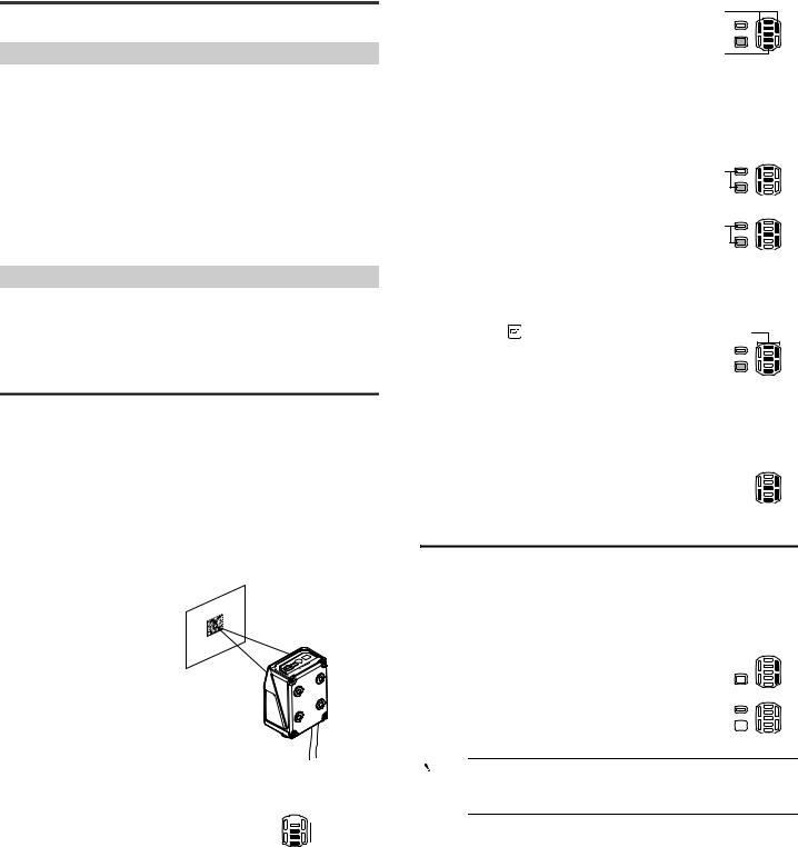
Activation using AutoID Network Navigator
Quick calibration is performed using AutoID Network Navigator. Confirming the actual scanned image, you can operate calibration.
1 Connects the SR-750 Series to the AutoID Network Navigator
The following screen will appear when the SR-750 Series is detected. Confirm that the indicator displayed on the left of the reader name lights up in green or blue.
Lights up in green or blue
2 Click the [Pointer] button.
The laser pointer of the SR-750 Series lights up. Adjust the center of the code to the position where the laser pointer emitted.
3 Click the [Monitor] button.
Looking at real-time scanned images, you can confirm the code positions. Adjust the brightness using the "Brightness adjustment bar" on the right. After the code position is determined, press the "Monitor" button to finish the setting.
Brightness adjustment bar
4 Click [Calibration] button.
The most appropriate scan condition is automatically set according to the code. Settings are registered with bank, and the operation finishes.
5 Perform the reading test.
Perform the reading rate test and processing time test, and confirm the reading stability of the calibration result.
• Reading rate test display screen |
• Processing time test display screen |
3-3 Alternate Function
This section describes the alternate function.
Alternate Function
The SR-750 Series can perform the reading operation while switching between multiple parameter banks that are registered for the code being read.
The function that performs reading operation with the most appropriate parameter while automatically switching the parameter bank - this is called "Alternate Function".
Even when there are fluctuations in printing conditions or reading distance, since it operates by switching between multiple parameter banks during a single read operation, a stable read operation is provided.
By default, read operation is performed using the parameter bank 0 (bank for read quick setup code).
Parameter banks
The SR-750 Series sets parameters necessary for code recognition such as scan conditions and filter conditions.
Location where this setting is stored is called a "Parameter Bank".
The SR-750 Series has 10 parameter banks. Multiple optimal parameters can be registered according to work conditions and printing conditions.
The following settings are stored in the parameter bank.
• Code type............................ |
Set the version of the code to be read, the number of |
|
codes, and the output length limitation function. |
• Internal light/External light... |
Set whether or not to use internal lighting and |
|
external lighting. |
•Scan conditions................... Set exposure time, gain, and dynamic range.
•Filter .................................... Set the filter condition to be used.
•Others ................................. Set the alternate, decoding area, algorithm, etc.
Alternate Function Operations
The following flow chart illustrates operations that occur during the alternate function:
|
|
Start reading |
|
|
|
Select parameter bank |
YES |
|
|
|
|
|
|
Scanning |
|
NO |
|
Decoding |
|
|
|
|
|
Reading success |
YES |
Was reading |
|
|
|
||
|
|
successful? |
|
|
|
|
YES |
|
|
NO |
|
|
|
Decode timeout |
Retry possible? |
|
|
period remains? |
|
|
|
|
|
|
|
NO |
NO |
|
|
|
Level trigger Read error YES turned off?
or One-shot timeout?
* Reading starts from the bank set as the "Alternate start bank".
 Important Since the alternate function cycles through the parameter banks one at a to determine the optimal settings, overall processing time may increase. (The processing time depends on the decode timeout period setting.)
The alternate function is turned off by default. The function is enabled automatically after the Tuning operation has been performed on any of the parameter banks.
The alternate function is disabled in the following cases:
•When using the read mode in the burst mode
•When the alternate function is turned off for all parameter banks
•When the bank specify trigger input command (LON01 to 10) is sent to directly specify the parameter bank for reading.
11 |
E SR-750 UM |
Bank prioritizing function
When the alternate setting order is set to "Begin with successful bank", the next reading starts from the parameter bank of the most recent successful reading. When codes with similar conditions are read in sequence, prioritizing according to the last successful bank may result in a shorter reading processing time.
Operation of the bank prioritizing function when parameter banks 1 to 4 are used
The reading order is changed to start reading from the parameter bank of the previous successful reading.
Reading |
Parameter bank |
|
|
Reading |
Parameter bank |
|||
order |
No. |
|
|
|
order |
No. |
||
1 |
|
1 |
|
|
|
1 |
3 |
|
|
|
|
||||||
|
|
|
|
|
|
|
|
|
|
|
|
|
|
|
|
|
|
2 |
|
2 |
|
|
2 |
1 |
||
|
|
|
Reading |
|
|
|
||
|
|
|
|
|
|
|||
3 |
|
3 |
3 |
2 |
||||
|
|
|
||||||
Success |
||||||||
|
|
|
|
|
|
|||
|
|
|
|
|
|
|
|
|
4 |
|
4 |
|
|
4 |
4 |
||
|
|
|
|
|
|
|
|
|
|
|
|
|
|
|
|
|
|
Point |
|
The bank prioritizing function is effective only in Operation mode. |
|
|
|
|
|
The reading order is reset to the default setting when one of the |
|
|
following operations is performed: |
|
|
• Stopping the power supply |
|
|
• Entering the test mode |
|
|
• Entering Setting mode or Test mode |
|
|
• Changing the alternate setting |
|
|
|
3-4 Test Mode
This section describes the test mode of the SR-750 Series.
SR-750 Series Test Mode
Function |
|
Description |
Reading rate test mode |
Offline |
Scans codes 10 times and measures the |
|
|
reading rate according to the number of times |
|
|
that the code was read correctly. |
|
|
|
|
Offline |
This test mode checks the number of |
|
|
successful decodes against the number of |
|
|
decodes attempted while the trigger input is |
|
|
turned ON. |
|
|
|
Read time test mode |
Offline |
This test mode measures the amount of |
|
|
decode time that it takes to read a code and |
|
|
outputs the result every 10 decodings are |
|
|
performed. |
|
Offline |
This test mode measures the amount of time |
|
|
that it takes to read a code and outputs the |
|
|
result when the trigger input turns OFF. |
|
|
|
Code position measurement |
Offline |
In this test mode, the level that indicates how |
test mode |
|
far the code shifts from the center of the field of |
|
|
view is measured. |
|
|
|
For more information about the TEST button operations of the SR-750 Series or the multiple LED status display, refer to  "3-1 Using the SR-750 Series (Page 9)".

 Reference • It is also possible to perform the test mode by specifying a parameter bank.
 "8-2 Operation Commands (Page 71)"
•If no parameter banks have setting values, the test mode is performed for the parameter bank 0 (bank for read quick setup code).
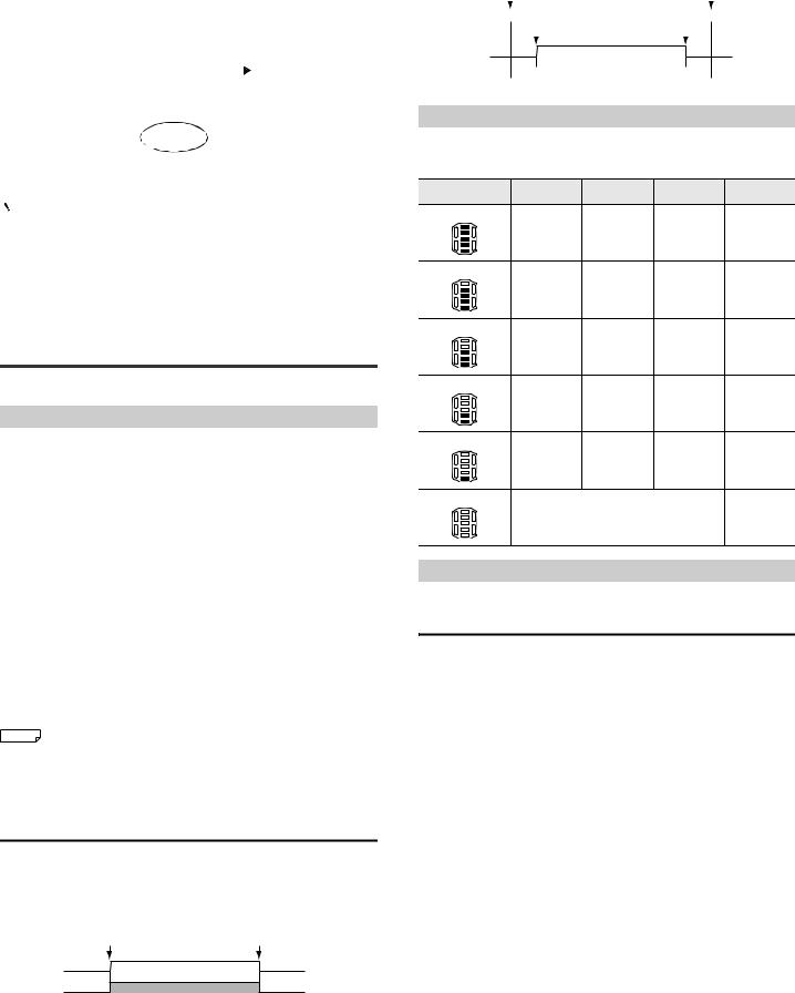
Online and offline modes
Offline mode
Offline mode is useful for fine-tuning the installation position, distance or angle during initial setup.
Data is continuously output as long as the test is active. The test result data is output in real time.
Activate the test. |
Stop the test. |
Test operations
Testing
Testing
Online mode
Online mode is useful for troubleshooting issues during run-time operation. Online test mode can only be enabled through serial command input.
 "8-2 Operation Commands (Page 71)"
To begin the test, turn the timing input on. To end the test and output results, turn the timing input off.
|
Activate the test. |
|
Stop the test. |
||||||
Test commands |
|
|
|
|
|
|
|
|
|
|
|
|
|
|
|
|
|
|
|
|
|
|
|
|
|
|
|||
|
|
|
Timing ON |
Timing OFF |
|
|
|||
|
|
|
|
||||||
Timing operation |
|
|
|
|
|
|
|
|
|
|
|
|
|
|
|
|
|
|
|
|
|
|
|
|
|
|
|
|
|
|
|
|
|
|
|
|
|
|
|
Testing |
|
|
|
|
|
Testing |
|
|
|
|
|
|
|
|
|
|
|
|
|
Test Mode Measurement Status
The measurement status of the test mode can be checked on the multiple LED indicator.
The multiple LED displays the following symbols during test mode.
Multiple LED status |
Reading rate |
Processing |
Code position |
OK/NG/ |
|
(%) |
time (ms) |
measurement |
ERROR LED |
||
|
|||||
5 bars lit |
|
|
|
|
|
|
90 to 100 |
Up to 99 |
LEVEL5 |
Green |
|
4 bars lit |
|
|
|
|
|
|
70 to 80 |
100 to 199 |
LEVEL4 |
Green |
|
3 bars lit |
|
|
|
|
|
|
50 to 60 |
200 to 299 |
LEVEL3 |
Green |
|
2 bars lit |
|
|
|
|
|
|
30 to 40 |
300 to 399 |
LEVEL2 |
Green |
|
1 bar lit |
|
|
|
|
|
|
10 to 20 |
400 or more |
LEVEL1 |
Green |
|
0 bars lit |
|
|
|
|
|
|
|
Reading error |
|
Red |
Test Mode Details
This section describes the advanced details of each test mode.
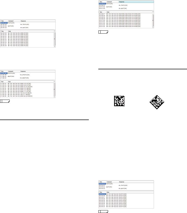
Reading rate test mode
This test mode scans codes and measures the number of successful reads. The offline mode scans 10 times and outputs the number of successful reads.
The offline test mode outputs the reading rate which is obtained from the number of decodes against the number of decodes attempted while the trigger input is ON.
The parameter bank switches while scanning, just as when reading with the alternate function. When reading is successful, the parameter bank used for reading is fixed and the reading rate is calculated.
When a read error occurs, the test mode switches to another parameter bank and continues the measurement.
E SR-750 UM |
12 |
Starting reading rate test mode
The following procedures can be used to start and stop the reading rate test mode:
•Start: Hold the  button for 2 seconds. Stop: Tap the button once briefly.
•Start: Send the TEST1 (#TEST1) command from the control host. Stop: Send the QUIT command (#QUIT) from the control host.
•Using AutoID Network Navigator or direct serial commands, assign "TEST" and "Reading rate test mode" to one of the IN terminals.
Start: Turn the input on Stop: Turn the input off
Reading rate test mode output data
Offline mode
The offline mode outputs data in the following format every 10 reading operations.
Read data |
: |
a |
: |
b |
% |
: |
d |
|
|
|
|
|
|
|
|
a = Parameter bank numbers (01 to 10)
b = Reading rate (1 to 100)
d = Average brightness value in code region
(0 to 255)
Online mode
The online mode outputs data in the following format when the trigger input is turned off.
Read data |
: |
a |
: |
b |
% |
: |
c |
: |
d |
|
|
|
|
|
|
|
|
|
|
a = Parameter bank numbers (01 to 10)
b = Reading rate (1 to 100)
c = Number of decoding successes/ Number of decoding operations
d = Average brightness value in code region
(0 to 255)
|
Reference |
• When starting test mode, the data addition function is inactive. |
•When TEST1nn (#TEST1nn) (nn: Parameter bank No.) is sent, the reading rate test mode is run for the bank with the specified parameter bank number.
Read time test mode
This test mode measures the amount of time that it takes to read a code and outputs the result.
The parameter bank switches while scanning, just as when reading with the alternate function. If reading is successful, the amount of time required from the start of reading until the completion of reading is measured and output. If the decoding fails, the read time becomes 0 ms.
Starting read time test mode
The following procedures can be used to start and stop read time test mode:
•Start: Hold the  button for 3 seconds. Stop: Tap the button once briefly to finish.
•Start: Send the TEST2 (#TEST2) command from the control host. Stop: Send the QUIT command (#QUIT) from the control host to finish.
•Assign "TEST" and "Reading rate test" to one of the IN terminals. Start: Turn on the input
Stop: Turn off the input
Read time test mode output data
Offline mode
The offline mode outputs data in the following format every 10 successful decodings or every time the decoding fails.
Online mode
The online mode outputs data in the following format when the trigger input is turned off.
(The format is the same for offline and online modes.)
Read data |
: |
a |
: |
now = b ms |
: |
max = c ms |
: |
min = d ms |
|
|
|
|
|
|
|
|
|
a = Parameter bank No. (00 to 10)
b = Latest reading time c = Maximum read time
(Maximum value of the read operation from starting the read time test mode to outputting data)
d = Minimum read time (Maximum value of the read
operation from starting the read time test mode to outputting data)
* The values for b, c, and d will be zero suppressed.
|
Reference |
• When starting test mode, the data addition function is inactive. |
•When TEST2nn (#TEST2nn) (nn: Parameter bank No.) is sent, the read time test mode is run for the bank with the specified parameter bank number.
•When the TEST2nn (#TEST2nn) command is sent or when there is only 1 parameter bank for reading, the specified decode timeout period is ignored and read operation is performed with a decode timeout period of 2550 ms. If it has been determined that the image cannot be decoded, measurement of the image is stopped without waiting for the decode timeout period expiration.
Code position measurement test mode
This test mode measures how far the code shifts from the center of the field of view.
This test mode can be used to perceive the amount of displacement and adjust both the code position and the SR-750 Series installation location.
Ideal position (LEVEL5) |
|
Shifted position (LEVEL1) |
|
|
|
The center of the code should coincide with |
The code is displaced from the center of the |
the center of the field of view. |
field of view. |
Starting code position measurement test mode
The following procedures can be used to start and stop code position measurement mode:
•Start: Hold the  button for 4 seconds. Stop: Tap once briefly to finish.
•Start: Send the TEST3 command from the control host. Stop: Send the QUIT command from the control host.
•Assign "TEST" and "Positioning Test" to one of the IN terminals. Start: Turn the input on
Stop: Turn the input off
Code position measurement test mode output data
During code position measurement test mode, data of the average of 10 scans (the fractional portion is dropped) is sent to the computer in the following format after scanning 10 times:
Read data |
: |
a |
: |
level = b |
|
|
|
|
|
a = Parameter bank No. (00 to 10)
b = Position level (0 to 5)
|
Reference |
• When starting test mode, the data addition function is inactive. |
•The code position measurement test mode does not run in online mode.
•When TEST3nn (nn: Parameter bank No.) is sent, the code position test mode is run for the bank with the specified parameter bank number.
13 |
E SR-750 UM |
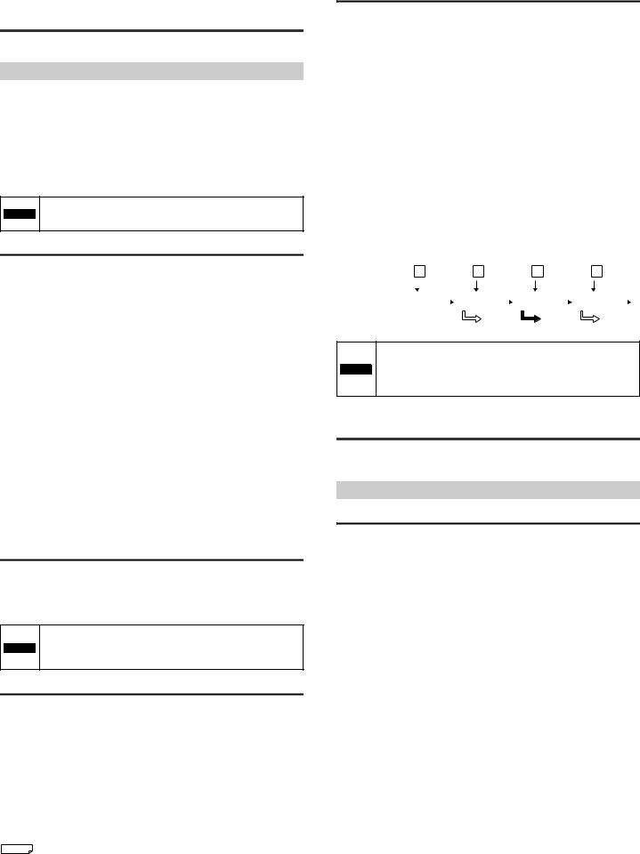
3-5 Preset/Verification
Function
This section describes the preset/verification function.
Preset/Verification Function
This function allows the SR-750 Series to verify the read code data against the registered code data (preset data), and output an OK/NG signal to indicate whether or not they match. This allows the SR-750 Series to perform simple detection of different codes without a sensor or other devices.
One set of preset data can be stored in the SR-750 Series (maximum 494 digits). The starting digit (starting position) and range (number of digits) for the verification can be set in the preset data, so even codes with more than 494 digits can be verified.
*If the multi 2 read mode or multiple read mode is set, the preset verification function cannot be used.
The verification starts at the specified starting position on the
NOTICE preset data and continues for the specified number of digits. Data cannot be verified at multiple points.
Registering preset data
Use one of the following procedures to register preset data with the SR-750 Series:
•Read a target code by turning on the external input terminal.
*You need to assign the preset data input function to the external input terminal in advance.
 "3-6 Multi-I/O Function (Page 14)"
•Set with the AutoID Network Navigator  "5-4 Details of Settings View (Page 34)"
•Set with a setup command  "8-3 Details of Configuration Commands (Page 75)"
Output data format for the preset registration result
The following output data format is used when the preset data is registered.
PR |
|
nn |
: |
|
Result data |
|
nn = Preset registration result (00 to 05) |
|
|
|
|
|
|
|
|
|
|
|
|
|
|
|
|
|
|
|
nn |
|
|
|
Description |
|
Result data |
||
00 |
Preset registration success |
|
Read data |
|||||
|
|
|
|
|
|
|||
01 |
Preset read failure |
|
|
|
Read error data |
|||
|
|
|
||||||
02 |
The preset effective digit is specified as 0. |
|
||||||
|
|
|
||||||
03 |
The number of digits of read data is less |
|
||||||
than the number of digits for preset start. |
|
|||||||
|
|
|||||||
|
|
|
[null] |
|||||
|
The preset registration is not possible |
|
||||||
04 |
because the operation mode is set to multi |
|
||||||
|
2 or multiple read. |
|
|
|
|
|||
|
|
|
|
|||||
05 |
Two or more "!" exist in preset data. |
|
|
|||||
|
|
|
|
|
|
|
|
|
Output terminal operation
The output terminals perform the following operation:
•Reading successful and matches preset data ............. OK is output
•Reading successful but does not match preset data ... NG is output
•Read error.................................................................... ERROR is output
•Preset data is registered successfully.......................... PRESET OK is output
By default, the PRESET OK output is not assigned to any of the OUT1 to OUT3 terminals. To connect the PRESET OK output to an
NOTICE external device, assign the PRESET OK output to an appropriate OUT terminal.
Functions of "!" and "?" in the preset data (wild cards)
Registering "!" or "?" with the preset data increases the flexibility when comparing and verifying the code data against the preset data.
"!" .......This character represents an unlimited number of digits and can be used when any character for any number of digits is OK. If the preset data is "A B C!", all codes that begin with "ABC" are verified as a match. If the preset data is "!ABC", all codes that end with "ABC" are verified as a match. A maximum of 1 "!" can be registered with the preset data.
"?" ......This character represents 1 digit and can be used when any one character is OK. If the preset data is "A B??5 6", any 2 characters positioned in ?? are verified as a match. If the preset data has not been registered, "!" is registered instead. Consequently, OK is output when a barcode is read successfully and ERROR is output when reading fails, regardless of the data of the bar code.

 Reference By default, the PRESET output is not assigned to any of the OUT1 to OUT4 terminals. To connect the PRESET OK output to an external device, you need to assign the PRESET OK output to an appropriate OUT terminal.
Sequence Verification Function
This function allows verification of codes including numerical values which change in series, such as workpiece serial numbers.
When the verification is OK, a value is added to/subtracted from the preset value. When the verification is NG, neither addition nor subtraction is performed.
When the sequence verification is set, the first data read after the setup or poweron is used as the preset data, and the numerical data for the number of digits set is verified.
When the PRESET input terminal is turned on during the automatic increment verification, the current preset value is cleared, and the data to be loaded next is used as the first load data.
The sequence verification requires the following settings:
•Verification method .........Select "Sequential".
•Starting digit ....................Set the number of digits where the value verification
|
starts. |
• No. of digits ("Length") .... |
For the numerical verification, the acceptable number |
|
of digits is 1 to 9 digits. |
• Increment ........................ |
Enter a value used to add to or subtract from the read |
|
code value. (-9999 to 9999) |
The following is the operation example when the starting digit is the third one, two digits are referenced and an increment of +2 is specified:
|
|
First reading |
Reading + Verification |
Reading + Verification |
Reading + Verification |
||||||||||||||||
Data |
|
A0 96 B··· |
|
|
A0 98 B··· |
|
A0 96 B··· |
|
|
A0 00 B··· |
|||||||||||
|
Preset value |
|
|
Verification |
|
|
Verification |
Verification |
|||||||||||||
|
|
||||||||||||||||||||
|
+2 |
|
|
|
|
|
|
Numerical value |
|
|
Numerical value |
||||||||||
|
|
|
|
|
|
|
|
|
|
+ 2 |
|
|
|
|
|
|
|
+ 2 |
|
||
Preset value |
|
98 |
|
|
|
98 |
|
00 |
|
|
|
00 |
|||||||||
|
|
|
|
|
|
|
|
|
|
|
|
|
|
||||||||
|
|
|
|
|
|
|
|||||||||||||||
|
|
|
|
|
|
|
|
|
"Verification |
|
"Verification |
|
"Verification |
||||||||
|
|
|
|
|
|
|
|
|
OK" |
|
NG" |
|
|
OK" |
|||||||
The following restrictions are placed on the sequence verification function:
NOTICE • The verification results in NG when a value other than a numerical value is read.
• The preset data cannot be registered through communication.
3-6 Multi-I/O Function
You can assign various operating conditions to the I/O terminals of the SR-750 Series. This section describes operations available with the Multi-I/O function.
Function and Operation of the Input Terminals (IN1 and IN2)
Functions assigned to the input terminals
Only 1 of the following functions can be assigned to each of the input terminals IN1 and IN2:
•Trigger input: Use as the input terminal to start/stop reading codes.
•Preset data input: Use as the input terminal to register preset data.
•Start test mode: Use as an input terminal to activate the specified test mode. (This function cannot be used to start the online test mode.)
•Clear PLC link error: Use as the terminal to clear the PLC link error.
•Tuning operation: Use the terminal to activate the quick calibration function.
•None: Select this option when the terminal is not used as an input terminal. Use AutoID Network Navigator or setup command to change the setting or assign the desired function.
*By default, the functions are assigned as follows: IN1: Trigger input
IN2: Preset input
E SR-750 UM |
14 |

Input terminal status and operation
The table below shows the relationship between the status of the input terminal and the operation of the assigned function.
Function assigned to the |
ON |
OFF |
|
input terminal |
|||
|
|
||
Trigger input (TIMING) |
Start reading. |
Stop reading. |
|
|
|
|
|
Preset input (PRESET) |
Start preset data registration. |
Finish preset data registration. |
|
|
|
|
|
Start test mode. (TEST) |
Activate the test mode. |
Quit the test mode. |
|
|
|
|
|
Stop PLC error |
Stop error |
― |
|
|
|
|
|
Tuning operation (TUNING) |
Start quick calibration |
Quit quick calibration |
|
|
|
|
Synchronous IN LED
Users can set the SR-750 Series to illuminate its IN LED when the IN1 or IN2 terminal turns on. When both IN1 and IN2 terminals synchronize with the IN LED, the LED illuminates based on the OR condition of the terminal status.
(By default, only the IN1 terminal synchronizes with the LED.)
Input polarity setting
The polarity of the input terminal can be selected from "N.O. (normally open) contact" or "N.C. (normally closed) contact".
(By default, "N.O. contact" is selected.)
The same input polarity is set for IN1 and IN2.
Power-on trigger setting
Normally, the input terminal recognizes the change in the input signal (ON/OFF) after the SR-750 Series is turned on and its operation stabilizes.
The input terminal does not operate if the input signal turns on before the operation stabilizes (approximately 500 ms after power on).
If "Power-on trigger" is enabled, the SR-750 Series recognizes the input ON status during the start-up period, and after the operation stabilizes, it performs the operation specified for the input signal.
(By default, "Power-on trigger" is disabled.)
Operation of Norm. open and Norm. closed
Norm. open (Normally open)
• Normal
Timing input
 ON
ON
Reading operation
Norm. closed (Normally closed)
• Normal
Timing input
 ON
ON
Reading operation
• Power-on trigger setting
Timing input
 ON
ON
Reading operation
Required input duration setting
Users can set the "Required input duration", which is the period required for the ON status of the input terminal to be recognized. The function assigned to the input terminal is activated after the input stays on for specified time or longer. (Required input duration setting range: Selectable from 1 ms, 2 ms or 10 ms; default setting is 1 ms.)
Function and Operation of the Output Terminals (OUT1, OUT2 and OUT3)
Functions assigned to the output terminals
The following functions can be assigned to the output terminals (OUT1 to OUT3). You can assign one or more functions to each output terminal.
Result output
This function outputs judgment results according to the SR-750 Series operation.
• OK.................... |
This signal is output when a bar code is read successfully or |
|
when the comparison/verification against preset data matches. |
• NG.................... |
This signal is output when the comparison/verification against |
|
the preset data does not match. |
•ERROR ............ This signal is output when a read error occurs.
•STABLE............ This signal is output when reading is stable ("Matching level
assessment function" or "Code quality verification function" is enabled and the matching level or Code quality verification result exceeds the set threshold).
• UNSTABLE ...... This signal is output when reading is unstable ("Matching level assessment function" or "Code quality verification function" is enabled and the matching level or Code quality verification result falls below the set threshold).
• PRESET OK .... This signal is output when the preset data is registered successfully.
• TUNING OK ..... This signal is output when the calibration is complete.
Operation output
This output function notifies that the SR-750 Series is currently running.
• TRG BUSY.......... During the start-up period, trigger input, preset data registration, calibration, test mode, or while images are being sent to FTP, bank numbers are being displayed, live view data are being sent, monitoring is being performed, while the laser pointer is on, images are being saved to ROM, the quick setup codes are being read or being scripted
•LOCK BUSY ....... Forced trigger lock is being applied.
•MODE BUSY....... The quick setup code is being read, during test mode
•ERR BUSY.......... Error occurred (buffer full, setting save error)
External light control output
• EXT. LIGHT......... |
This signal is output to control external illumination. |
|
|
|
|
|
• The result outputs (OK, NG, ERROR, STABLE, UNSTABLE, |
|
|
PRESET OK, TUNING OK) and the outputs in operation (TRG |
|
|
BUSY, LOCK BUSY, MODEBUSY, ERR BUSY) and EXT.LIGHT |
|
NOTICE |
cannot be set for the same terminal. |
|
|
• EXT.LIGHT can be assigned to OUT3 only. Also, when |
|
|
EXT.LIGHT is assigned to OUT3, no other output can be |
|
|
assigned to OUT3. |
|
Output terminal operation
The output terminals operate differently depending on the assigned function. There are three types of operations as shown below:
OK, NG, ERROR, STABLE, UNSTABLE, PRESET OK, and TUNING OK output
The above signals turn on the output for the specified output ON time when the respective event occurs.
|
ON |
|
Event occurrence |
|
|
OK/NG/ERROR |
ON |
|
STABLE/UNSTABLE |
|
|
PRESET OK/TUNING OK |
|
Period of time set for output ON time |
*For the above output functions, a higher priority is assigned to the output of the function which occurred last.
Consequently, when the next operation occurs during the output ON time of the previous operation, the signal is switched to output the signal of the higher priority function.
15 |
E SR-750 UM |
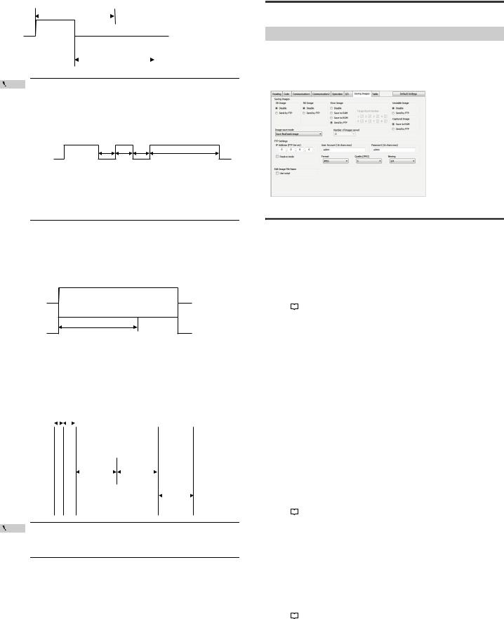
Timing diagram (When OUT1 outputs an OK signal and then OUT2 outputs a NG signal)
|
Period of time set for output ON time |
|
|||||
|
|
|
|
|
|||
|
ON |
|
|||||
OUT1 |
|
|
|
|
|
|
|
(OK) |
|
|
|
|
|
|
|
OUT2 |
|
ON |
|
|
|
|
|
|
|
|
|
|
|||
|
|
|
|
|
|
|
|
|
|
Period of time set for output ON time |
|
||||
(NG) |
|
|
|
||||
|
|
|
|
|
|
|
|
Point |
If the same operation occurs again within the period of the output |
|
ON time, the output turns off for 10 ms and then turns on again to output the signal of the next operation. (If the same operation occurs continuously at short intervals, the output turns on for at least 10 ms before it turns off and then turns on again.)
Timing diagram (When OUT1 outputs signals continuously)
OUT1 |
ON |
|
|
|
10 ms |
10 ms |
10 ms |
||
(OK) |
||||
|
|
Period of time set for output ON time |
||
|
|
|
Other than the example described above, the signal is switched when any of the following events occurs:
•Change to Test mode/Read quick setup mode
•Laser pointer is turned on
•Error
•Buffer full
TRG BUSY, LOCK BUSY, MODE BUSY and ERR BUSY output
The above signals are retained until the corresponding event ends.
(The period is not affected by the period of time set for the output ON time.)
Event occurrence |
Event end |
Event occurrence |
|
TRG BUSY/ |
ON |
|
LOCK BUSY/ |
||
|
||
MODE BUSY/ |
Period of time set for output ON time |
|
ERR BUSY |
*If multiple BUSY outputs are assigned to one output terminal, the output signal is turned off when all events finish.
EXT.LIGHT (external illumination) output
The above signal is output in synchronization with the scan timing.
The output polarity can be selected from "N.O. (normally open) contact" or "N.C. (normally closed) contact".
The timing diagram shows the operation for the N.O. contact:
Input pulse width |
Scan delay time |
|
|
|
|
|
|
|
|
|||||||
|
|
|
|
|
|
|
|
|
|
|
|
|
|
|
|
|
Trigger input |
|
|
|
|
|
|
|
|
|
|
|
|
|
|
|
|
|
|
|
|
|
|
|
|
|
|
|
|
|
|
|
||
|
|
|
|
|
|
|
|
|
|
|
|
|
|
|
|
|
EXT.LIGHT output |
|
|
|
|
|
|
|
|
|
|
|
|
|
|||
|
|
|
|
|
|
|
|
|
|
|
|
|
||||
|
|
|
|
|
|
|
|
|
|
|
|
|
|
|
|
|
|
|
|
|
|
|
|
0.09 to 9.99 ms |
|
Approx. 16 ms |
|||||||
Scanning |
|
|
|
|
|
|
|
|
|
|
|
|
||||
|
|
|
|
|
|
|
|
|
|
|
|
|
||||
|
|
|
Exposure time |
Image capture time |
|
|
|
|
|
|||||||
|
|
|
|
|
|
|
|
|
|
|
|
|
Decode timeout |
|
|
|
|
|
|
|
|
|
|
|
|
|
|
|
|
period |
|||
Decoding |
|
|
|
|
|
|
|
|
|
|
|
|
|
|
||
|
|
|
|
|
|
|
|
|
|
|
|
|
||||
Point |
• EXT. LIGHT can be assigned to OUT3 only. |
|
•When EXT. LIGHT is assigned to OUT3, no other output can be assigned to OUT3.
3-7 Image Saving Function
This section describes the image saving function of the SR-750 Series.
Image Saving Function
The image saving function is used to save the scan image into RAM/ROM of the SR-750 Series based on the image saving mode settings or to send to PC via FTP communication.
Saved images can be used for analyzing causes of read error, etc.
• AutoID Network Navigator setting screen
Type of images to be saved
Latest image
The SR-750 Series stores a scanned image to RAM temporarily and performs decoding process for the image data.
The image before decoding process is called the "Latest image".
•The "Latest image" saves up to 10 images to RAM in one time reading operation.
•The type of image of the "Latest image" is set to "L" for the file name.
•To confirm the "Latest image", use the image view function and file view function
of the AutoID Network Navigator.
Refer to |
|
"5-10 ImageView (Page 52)""5-11 FileView (Page 53)" |
|
Judged image
An Image for which decoding process is performed and the read result is judged is called "Judged image".
The "Judged image" can be set for each judged result.
• Read OK, Verification NG, Unstable image
|
: Not save or FTP transmission |
• Read error |
: Not save, RAM save, ROM save or FTP |
|
transmission |
The "Judged image" is saved according to the following rules.
•The number of judged images to be saved varies according to the reading operation and image saving mode. (Max. 10)
•The type of image for the file name of the "Judged image" is set as follows according to the judged result.
Reading success |
: S |
Reading error |
: E |
Verification NG |
: N |
Unstable image |
: W |
Decoding process |
: X....... The image was scanned in the burst read mode, |
not performed |
but the decoding process was not performed. |
•To confirm the "Judged image" saved into RAM/ROM, use the image view function and file view function of the AutoID Network Navigator.
Refer to |
|
"5-10 ImageView (Page 52)""5-11 FileView (Page 53)" |
|
Capture image
This is an image scanned using the capture function of the SR-750 Series. One image is saved with one-time capture operation.
You can select either RAM or FTP transmission as the save destination for capture images.
•Capture operation can be performed using the image view function or operation command.
•The type of image is set to "C" for the file name of the "Capture image".
•To confirm the "Capture image" saved into RAM, use the image view function and file view function of the AutoID Network Navigator.
Refer to |
|
"5-10 ImageView (Page 52)""5-11 FileView (Page 53)" |
|
E SR-750 UM |
16 |

Image file name
An image file name is set in the following format.
(1) |
_ |
(2) |
_ |
(3) |
_ |
(4) |
. |
(5) |
|
|
(1) Image count value (3 bytes) |
IMG |
: When saved in ROM/RAM |
||||||||
|
|
|
|
|
|
|
000 to 999 |
: When sent via FTP |
||
|
|
|
|
|
|
|
|
|
|
• The number is counted from 000 |
|
|
|
|
|
|
|
|
|
|
at startup. |
|
|
|
|
|
|
|
|
|
|
• The counter value is |
|
|
|
|
|
|
|
|
|
|
incremented each time one |
|
|
|
|
|
|
|
|
|
|
image is sent. |
|
|
|
|
|
|
|
|
|
|
• When the counter value of 999 is |
|
|
|
|
|
|
|
|
|
|
incremented, the value returns to |
|
|
|
|
|
|
|
|
|
|
000. |
(2) Image type (1 byte) |
S |
: OK image |
||||||||
|
|
|
|
|
|
|
L |
: Latest |
||
|
|
|
|
|
|
|
E |
: Error image |
||
|
|
|
|
|
|
|
W |
: Unstable image |
||
|
|
|
|
|
|
|
N |
: Comparison NG |
||
|
|
|
|
|
|
|
C |
: Captured image |
||
|
|
|
|
|
|
|
X |
: No decoding process |
||
(3) Operation number (2 bytes) |
00 |
|
|
: Latest |
||||||
|
|
|
|
|
|
|
01 to 10 |
: From timing ON/OFF to specified |
||
|
|
|
|
|
|
|
|
|
|
number |
|
|
|
|
|
|
|
#1 to #8 |
: Burst number |
||
(4) Bank number (2 bytes) |
01 to 10 |
|
||||||||
(5) Image file extension |
ROM/RAM |
: bmp |
||||||||
|
|
|
|
|
|
|
FTP |
: bmp or jpg |
||
When the edit image file name function is enabled
When sending images via FTP transmission with [Edit image file name] – [Use script] set to Enable, image file names can be freely changed.
For the edit image file name function, refer to  "3-13 Edit data function/Edit image file name function (Page 24)".
Image save mode
The following 3 image save modes are available:
•Save final bank image
•Save images after timing input ON
•Save images of the specified number before trigger input OFF This section describes each mode.
Save the latest bank image
In this mode, the SR-750 Series performs reading operation and saves the image at the timing when the read result is judged.
Depending on the reading mode of the SR-750 Series, saved images and the determination timing for images to be saved are as follows.
Refer to  "4-4 Read Mode (Page 28)"
Read OK/Comparison NG (When the preset/comparison function is used)/Unstable image
(1)When the reading mode is the single read mode or multi 1 read mode
Only successfully read images of both the latest images and judged images are saved.
(This is the example of when the parameter banks 1 to 3 are used.)
Trigger input
Latest image |
|
|
|
|
|
|
|
|
|
|
|
|
|
|
|
|
|
|
|
|
|
|
|
|
|
|
|
Parameter bank |
|
Bank |
|
Bank |
|
Bank |
|
Bank |
Bank |
|
|
|
|
|
|
1 |
|
2 |
|
3 |
|
1 |
|
2 |
|
|
|
Reading |
|
|
|
|
|
|
|
|
|
|
|
|
|
|
Failed |
|
Failed |
|
Failed |
|
Failed |
|
Success |
|
|
|
|
Success/Failed |
|
|
|
|
|
|
|
|
|||||
|
|
|
|
|
|
|
|
|
|
|
|
|
|
|
|
|
|
|
|
|
|
|
|
|
|
|
|
Judged image |
|
|
|
|
|
|
|
|
|
Bank |
|
|
|
|
|
|
|
|
|
|
|
|
|
2 |
|
|
|
|
|
|
|
|
|
|
|
|
|
|
|
|
|
Images to be saved
(2)When the reading mode is the multi 2 read mode
Judged images and parameter bank images successfully read are all saved. For the latest images, only the image obtained last is saved.
(This is the example of when the parameter banks 1 to 3 are used.)
Trigger input
Latest image |
|
|
|
|
|
|
Parameter bank |
Bank |
Bank |
Bank |
Bank |
Bank |
|
|
1 |
2 |
3 |
1 |
2 |
|
Reading |
Failed |
Failed |
Success |
Success |
Success |
|
Success/Failed |
||||||
|
|
|
|
|
||
Judged image |
|
|
Bank |
Bank |
Bank |
|
|
|
|
3 |
1 |
2 |
Images to be saved
(3)When the reading mode is the burst read mode
For the latest images, all burst scanned images are saved.
For the judged images, only the images that can be decoded are saved. (This is the example of when the burst execution bank is 1 and the number of burst scans is 5.)
Trigger input |
|
|
|
|
|
|
|
|
|
Latest image |
Scanning Scanning Scanning Scanning Scanning |
|
|
|
|
||||
1 |
2 |
3 |
4 |
5 |
|
|
|
|
|
|
|
|
|
|
|||||
Parameter bank |
Bank Bank Bank Bank Bank |
|
|
|
|
||||
1 |
1 |
1 |
1 |
1 |
|
|
|
|
|
|
|
|
|
|
|||||
Reading |
|
|
|
|
Scanning 1 |
Scanning 2 |
Scanning 3 |
Scanning 4 |
Scanning 5 |
Success/Failed |
|
|
|
|
Failed |
Failed |
Success |
- |
- |
|
|
|
|
|
|
|
|
|
|
Judged image |
|
|
|
|
|
|
Bank |
|
|
|
|
|
|
|
|
1 |
|
|
|
|
|
|
|
|
|
|
|
|
Images to be saved |
Read error
(1)When the reading mode is the single read mode or multi 1 read mode When a reading error occurs, all parameter bank images used for reading operation are saved one by one as judged images.
For the latest images, only the image obtained last is saved.
Trigger input
Latest image |
|
|
|
|
|
|
Parameter bank |
Bank |
Bank |
Bank |
Bank |
Bank |
|
|
1 |
2 |
3 |
1 |
2 |
|
Reading |
Failed |
Failed |
Failed |
Failed |
Failed |
|
Success/Failed |
||||||
|
|
|
|
|
||
Judged image |
|
|
Bank |
Bank |
Bank |
|
|
|
|
3 |
1 |
2 |
Images to be saved
17 |
E SR-750 UM |

(2)When the reading mode is the multi 2 read mode
In the multi 2 read mode, if reading judgments (Success or Failed) differ among parameter banks, the judged images of parameter banks that were judged as reading error are saved.
For the latest images, the image obtained last is saved.
Trigger input
Latest image |
|
|
|
|
|
|
Parameter bank |
Bank |
Bank |
Bank |
Bank |
Bank |
|
|
1 |
2 |
3 |
1 |
2 |
|
Reading |
Failed |
Failed |
Failed |
Success |
Failed |
|
Success/Failed |
||||||
|
|
|
|
|
||
Judged image |
|
|
Bank |
|
Bank |
|
|
|
|
3 |
|
2 |
Images to be saved
(3)When the reading mode is the burst read mode
If a read error occurs in the burst read mode, the judged images for the save target burst numbers are only saved.
For the latest images, all burst scanned images are saved.
Trigger input
Latest image
Parameter bank
Reading
Success/Failed
Judged image
Scanning |
Scanning |
Scanning |
Scanning |
Scanning |
|
|
|
|
1 |
2 |
3 |
4 |
5 |
|
|
|
|
Bank Bank Bank Bank Bank |
|
|
|
|
||||
1 |
1 |
1 |
1 |
1 |
|
|
|
|
|
|
|
|
Scanning 1 |
Scanning 2 |
Scanning 3 |
Scanning 4 |
Scanning 5 |
|
|
|
|
Failed |
Failed |
Failed |
Failed |
Failed |
|
|
|
|
Save |
|
Save |
|
Save |
|
|
|
|
target |
|
target |
|
target |
|
|
|
|
|
|
|
|
Images to be saved |
If the trigger input turns off before the decoding process for scanned images are not complete, the judged images as save targets are saved with the type of image "X" (Decoding process not performed).
|
Trigger input |
|
|
|
|
|
|
|
|
|
|
|
|
|
|
|
|
|
NOTICE |
Reading |
|
|
|
|
|
|
|
|
|
|
|
|
|
|
|
|
|
|
|
|
|
|
|
|
|
|
|
|
|
|
|
|
|
|||
|
Scanning 1 |
Scanning 2 |
Scanning 3 |
Scanning 4 |
Scanning 5 |
|
|
|
|
|||||||||
|
Success/Failed |
|
Failed |
Failed |
Failed |
Failed |
Failed |
|
|
|
|
|||||||
|
|
|
|
|
|
|
|
|
|
|
|
|
|
|
|
The type of image is "X" |
||
|
|
|
|
|
|
|
|
|
|
|
|
|
|
|
|
because decoding process |
||
|
Judged image |
Save |
|
Save |
|
|
Save |
|
is not performed. |
|||||||||
|
|
|
target |
|
target |
|
|
target |
|
|||||||||
|
|
|
|
|
|
|
|
|
|
|
|
|
|
|
|
|
|
|
|
|
|
|
|
|
|
|
|
|
|
|
|
|
|
|
Images to be saved |
||
|
|
|
|
|
|
|
|
|
|
|
|
|
|
|
|
|||
Save images of the specified number after trigger input ON
When the read result is judged, the SR-750 Series saves images of the specified number after the reading operation began.
Image saving timing
The timing when images to be saved are determined is the same as the timing when Read OK/Verification NG/Read error is judged.
The number of images to be saved can be specified by using AutoID Network Navigator or setting commands for both the latest images and judged images. (Max. 10 for each)
Trigger input |
|
|
|
|
|
|
|
|
|
|
|
|
|
|
Latest image |
|
|
|
|
|
|
|
····· |
|
|
|
|
||
|
|
|
|
|
|
|
|
|
|
|
|
|
||
|
Latest |
|
Latest |
|
Latest |
|
Latest |
Latest |
|
Latest |
|
|
||
|
|
1 |
|
2 |
|
3 |
|
4 |
|
n-1 |
|
n |
|
|
|
|
|
|
|
|
|
|
|
|
|
|
|
|
|
Parameter bank |
|
Bank |
|
Bank |
|
Bank |
|
Bank |
····· |
Bank |
|
Bank |
|
|
|
|
1 |
|
2 |
|
3 |
|
1 |
|
3 |
|
1 |
|
|
Judged image |
|
|
|
|
|
|
|
|
|
|
|
|
|
|
|
Judged |
|
Judged |
|
Judged |
|
Judged |
····· |
Judged |
|
Judged |
|
|
|
|
|
1 |
|
2 |
|
3 |
|
4 |
n-1 |
|
n |
|
|
|
|
|
The SR-750 Series saves images of the specified number (n) after the trigger input |
||||||||||||
|
|
turns ON. |
|
|
|
|
|
|
|
|
|
|
|
|
|
• When the reading mode is the multi 1 read mode, image saving |
|
|
is impossible with this operation. |
|
|
• When the reading result can be judged before reaching the |
|
NOTICE |
specified number, the images until that point are saved. |
|
• When the reading mode is the burst read mode, up to 8 images |
||
|
||
|
are saved. In the burst read mode, the SR-750 Series saves |
|
|
images of the specified number (burst scan count) for both the |
|
|
latest images and judged images. |
|
|
|
Save images of the specified number before trigger input OFF
When the read result is judged or the trigger input turns OFF, the SR-750 Series saves images of the specified number before then.
Image saving timing
The timing when images to be saved are determined is the same as the timing when Read OK/Verification NG is determined, or the trigger input turns OFF and Read error is determined.
The number of images to be saved can be specified by using AutoID Network Navigator or setting commands for both the latest images and judged images. (Max. 10 for each)
Trigger input
Latest image
Parameter bank
Judged image
|
Latest |
|
Latest |
|
Latest |
|
Latest |
····· |
Latest |
|
Latest |
|
|
1 |
|
2 |
|
3 |
|
4 |
|
n-1 |
|
n |
|
|
|
|
|
|
|
|
|
|
|
|
|
|
|
Bank |
|
Bank |
|
Bank |
|
Bank |
····· |
Bank |
|
Bank |
|
|
1 |
|
2 |
|
3 |
|
1 |
|
3 |
|
1 |
|
|
|
|
|
|
|
|
|
|
|
|
|
|
|
Judged |
|
Judged |
|
Judged |
|
Judged |
····· |
Judged |
|
Judged |
|
|
1 |
|
2 |
|
3 |
|
4 |
n-1 |
|
n |
|
The SR-750 Series saves images of the specified number going back from the image with the read result judged or the image when the trigger input turns OFF.
•Image number is counted in the obtained order as 1, 2, 3···.
•When the reading mode is the multi 1 read mode, image saving is impossible with this operation.
•When the reading result can be judged before reaching the specified number, the images until that point are saved.
NOTICE |
• When the reading mode is the burst read mode, up to 8 images |
|
|
|
are saved. In the burst read mode, the SR-750 Series saves |
|
images of the specified number (burst scan count) for both the |
|
latest images and judged images. |
3-8 Silent Mode
This section describes the silent mode of the SR-750 Series.
Silent mode
A typical code reader outputs data of the result when the code is read or the read error code when it is not read.
The SR-750 Series can be configured to restrain data communication and not to output the result data to the host computer.
This function is called "Silent mode".
For example, if the application only uses the OK, NG or Read Error terminal outputs, this information can be suppressed.
By configuring the SR-750 Series not to send all data, it eliminates the time required for data transmission to/from the host computer. As a result, overall reading time can be reduced.
Timing diagram (when OK/NG/ERROR data is restrained)
(When reading is successful) (When reading failed)
Trigger input
Code
Scanning + decoding
Data communication
OK/NG/ERROR output |
OK/NG |
ERROR |
TRG BUSY output
Only data is not sent as shown above, but the OUT output terminal performs normal operation.
*Even with the silent mode set, images can be saved with the condition set using the image save function.
Refer to  "3-7 Image Saving Function (Page 16)"
E SR-750 UM |
18 |
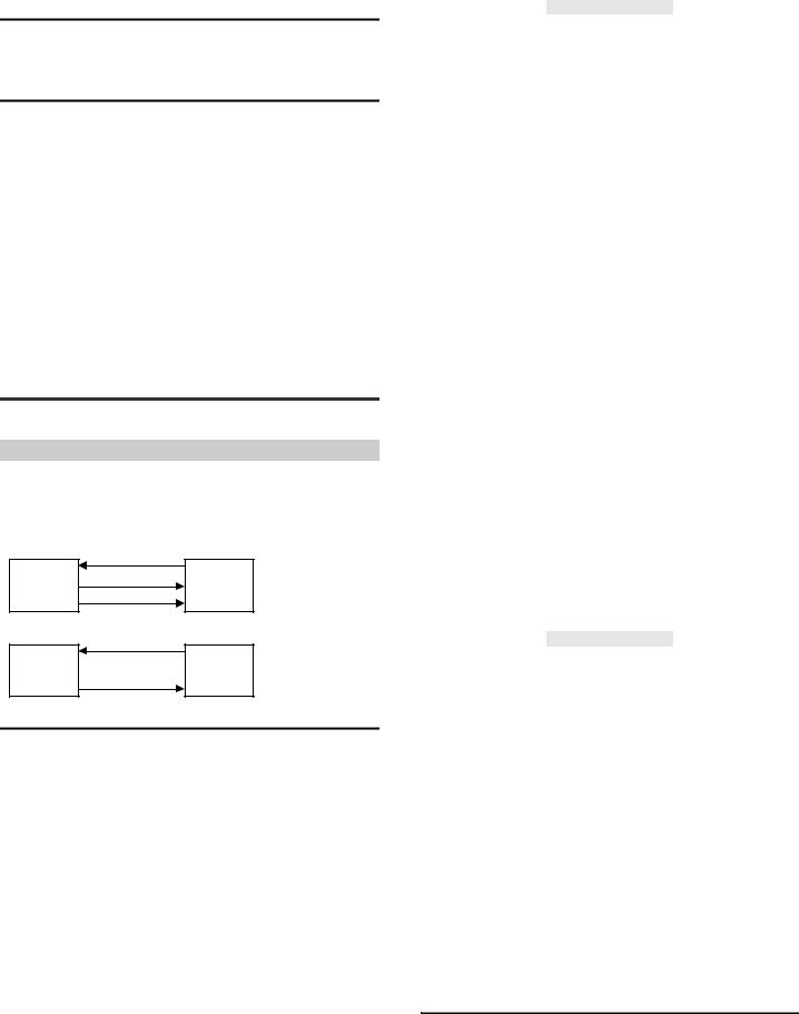
Silent mode setting procedure
The following 2 procedures for setting silent mode are available:
•Setting using the AutoID Network Navigator
•Setting with a command
Data subject to data communication restraint
By configuring the SR-750 Series, the following data communication can be restrained.
Setting items and setting details using the AutoID Network Navigator
Setting item |
Data subject to output restraint |
|
Read (Comparison) OK |
Read data |
|
Read data judged as Comparison OK as a result of preset verification. |
||
|
||
|
|
|
Comparison NG |
Preset Comparison NG data |
|
Read data judged as Comparison NG as a result of preset verification. |
||
|
||
|
|
|
Read ERROR |
Read error data |
|
|
|
|
Stable Reading (OK/NG) |
Stable reading data |
|
|
Read data whose matching level or Code quality verification |
|
|
result is judged as more than the threshold |
|
|
|
|
Unstable Reading (OK/NG) |
Unstable reading data |
|
|
Read data whose matching level or Code quality verification |
|
|
result is judged as less than the threshold |
|
|
|
|
Preset Result |
Preset registration result data |
|
|
|
|
Test Mode |
Measured data in test mode |
3-9 SR-600 Compatible Output Mode
This section describes the SR-600 compatible output mode of the SR-750 Series.
SR-600 compatible output mode
The SR-750 Series supports the Ethernet communication, so the operation command format and response code format have been changed from the previous SR-600 Series. When using the SR-750 Series in the SR-600 Series operation process or using the control program for the SR-600 Series, setting the SR-600 compatible output mode to Enable results in reduction in man-hours for program change.
• Standard mode
|
(1) LON |
SR-750 |
(2) OK, LON |
PC or PLC |
(3)Read data
•SR-600 compatible output mode
(1)LON
SR-750 |
PC or PLC |
(2) Read data
SR-600 compatible output mode functions
Commands and responses set to Enable in the SR-600 compatible output mode are as follows.
Operation commands
Command |
Command |
SR-750 Series normal output |
SR-600 Compatible output |
|||
name |
Response |
Error code |
Response |
Error code |
||
|
||||||
Trigger input ON |
LON |
|
|
|
|
|
|
|
OK, LON |
ER, LON, ee |
(N/A) |
(N/A) |
|
Trigger input ON |
LONbb |
|||||
(Bank settings) |
LON, bb |
|
|
|
|
|
|
|
|
|
|
|
|
Trigger input OFF |
LOFF |
OK, LOFF |
ER, LOFF, ee |
(N/A) |
(N/A) |
|
|
|
|
|
|
|
|
Start preset data |
PRON |
OK, PRON |
ER, PRON, |
(N/A) |
(N/A) |
|
registration |
ee |
|||||
|
|
|
|
|||
|
|
|
|
|
|
|
End preset data |
PROFF |
OK, PROFF |
ER, PROFF, |
(N/A) |
(N/A) |
|
registration |
ee |
|||||
|
|
|
|
|||
|
|
|
|
|
|
|
Start reading the |
RCON |
OK, RCON |
ER, RCON, |
OK |
ERRee |
|
quick setup code |
ee |
|||||
|
|
|
|
|||
|
|
|
|
|
|
|
End reading the |
RCOFF |
OK, RCOFF |
ER, RCOFF, |
OK |
ERRee |
|
quick setup code |
ee |
|||||
|
|
|
|
|||
|
|
|
|
|
|
|
Check the quick |
|
OK, RCCHK, |
ER, RCCHK, |
Obtained |
|
|
setup code |
RCCHK |
Obtained |
ERRee |
|||
ee |
value |
|||||
reading status |
|
value |
|
|||
|
|
|
|
|||
|
|
|
|
|
|
|
|
|
OK, INCHK, |
ER, INCHK, |
|
|
|
|
INCHK, m |
Obtained |
|
|
||
|
ee |
|
|
|||
Check the input |
|
value |
Obtained |
|
||
|
|
ERRee |
||||
terminal status |
INmCHK |
OK, INmCHK, |
ER, INmCHK, |
value |
||
|
||||||
|
Obtained |
ee |
|
|
||
|
|
value |
|
|
||
|
|
|
|
|
||
|
|
|
|
|
|
|
Output terminal |
OUTON, m |
OK, OUTON |
ER, OUTON, |
|
|
|
ON control |
ee |
Obtained |
|
|||
|
|
ERRee |
||||
(individual |
OUTmON |
OK, OUTmON |
ER, |
value |
||
|
||||||
control) |
OUTmON, ee |
|
|
|||
|
|
|
|
|
|
|
Command |
Command |
SR-750 Series normal output |
SR-600 Compatible output |
|||
name |
Response |
Error code |
Response |
Error code |
||
|
||||||
Output terminal |
OUTOFF, m |
OK, OUTOFF |
ER, OUTOFF, |
|
|
|
OFF control |
|
|
ee |
Obtained |
|
|
|
|
|
ERRee |
|||
|
|
ER, |
||||
(individual |
|
OK, |
value |
|||
OUTmOFF |
OUTmOFF, |
|
||||
control) |
OUTmOFF |
|
|
|||
|
ee |
|
|
|||
|
|
|
|
|
||
|
|
|
|
|
|
|
Output terminal |
|
|
ER, ALLON, |
|
|
|
ON control |
ALLON |
OK, ALLON |
OK |
ERRee |
||
ee |
||||||
(batch control) |
|
|
|
|
||
|
|
|
|
|
||
|
|
|
|
|
|
|
Output terminal |
|
|
ER, ALLOFF, |
|
|
|
OFF control |
ALLOFF |
OK, ALLOFF |
OK |
ERRee |
||
ee |
||||||
(batch control) |
|
|
|
|
||
|
|
|
|
|
||
|
|
|
|
|
|
|
Soft reset |
RESET |
OK, RESET |
(N/A) |
OK |
(N/A) |
|
|
|
|
|
|
|
|
Clearing the |
BCLR |
OK, BCLR |
(N/A) |
OK |
(N/A) |
|
send buffer |
||||||
|
|
|
|
|
||
|
|
|
|
|
|
|
Check reading |
|
OK, NUM, |
|
Obtained |
|
|
NUM |
Obtained |
ER, NUM, ee |
ERRee |
|||
history |
value |
|||||
|
value |
|
|
|||
|
|
|
|
|
||
|
|
|
|
|
|
|
Capture |
SHOTbb |
OK, SHOT, |
ER, SHOT, ee |
OK |
ERRee |
|
SHOT, bb |
File name |
|||||
|
|
|
|
|||
|
|
|
|
|
|
|
Start tuning |
TUNE, bb |
OK, TUNE |
ER, TUNE, ee |
OK |
ERRee |
|
|
||||||
TUNEbb |
||||||
|
|
|
|
|
||
Cancel tuning |
TQUIT |
OK, TQUIT |
ER, TQUIT, |
OK |
ERRee |
|
ee |
||||||
|
|
|
|
|
||
|
|
|
|
|
|
|
Obtain the |
|
OK, |
ER, |
Obtained |
|
|
BANKORDER |
BANKORDER, |
BANKORDER, |
ERRee |
|||
alternate order |
value |
|||||
|
Obtained value |
ee |
|
|||
|
|
|
|
|||
|
|
|
|
|
|
|
|
BANKCLR, |
|
|
|
|
|
Initialize the |
bb |
OK, |
ER, |
OK |
ERRee |
|
parameter bank |
BANKCLRb |
BANKCLR |
BANKCLR, ee |
|||
|
|
|||||
|
b |
|
|
|
|
|
|
|
|
|
|
|
|
Save setting |
SAVE |
OK, SAVE |
ER, SAVE, ee |
OK |
ERRee |
|
|
|
|
|
|
|
|
Initialize the |
DFLT |
OK, DFLT |
ER, DFLT, ee |
OK |
ERRee |
|
settings |
||||||
|
|
|
|
|
||
|
|
|
|
|
|
|
|
|
OK, |
|
|
|
|
Obtain the |
CMDSTAT |
CMDSTAT, |
(N/A) |
Obtained |
(N/A) |
|
command status |
Obtained |
value |
||||
|
|
|
||||
|
|
value |
|
|
|
|
|
|
|
|
|
|
|
|
|
OK, |
|
|
|
|
Obtain the error |
ERRSTAT |
ERRSTAT, |
(N/A) |
Obtained |
(N/A) |
|
status |
Obtained |
value |
||||
|
|
|
||||
|
|
value |
|
|
|
|
|
|
|
|
|
|
|
Erase error |
ICLR, bb |
OK, ICLR |
ER, ICLR, ee |
OK |
ERRee |
|
images |
ICLRbb |
|||||
|
|
|
|
|||
|
|
|
|
|
|
|
Test mode commands
Command |
Command |
SR-750 Series normal output |
SR-600 Compatible output |
|||
name |
Response |
Error code |
Response |
Error code |
||
|
||||||
Start reading |
TEST1 |
|
ER, TEST1, |
|
|
|
rate test mode |
TEST1, bb |
OK, TEST1 |
OK |
ERRee |
||
ee |
||||||
(offline) |
|
|
|
|
||
TEST1bb |
|
|
|
|||
|
|
|
|
|||
|
|
|
|
|
|
|
Start reading |
#TEST1 |
|
ER, #TEST1, |
|
|
|
rate test mode |
#TEST1, bb |
OK, #TEST1 |
OK |
ERRee |
||
ee |
||||||
(online) |
|
|
|
|
||
#TEST1bb |
|
|
|
|||
|
|
|
|
|||
|
|
|
|
|
|
|
Start processing |
TEST2 |
|
ER, TEST2, |
|
|
|
time test mode |
TEST2, bb |
OK, TEST2 |
OK |
ERRee |
||
ee |
||||||
(offline) |
|
|
|
|
||
TEST2bb |
|
|
|
|||
|
|
|
|
|||
|
|
|
|
|
|
|
Start processing |
#TEST2 |
|
ER, #TEST2, |
|
|
|
time test mode |
#TEST2, bb |
OK, #TEST2 |
OK |
ERRee |
||
ee |
||||||
(online) |
|
|
|
|
||
#TEST2bb |
|
|
|
|||
|
|
|
|
|||
|
|
|
|
|
|
|
Start position |
#TEST3 |
|
ER, TEST3, |
|
|
|
test mode |
#TEST3, bb |
OK, TEST3 |
OK |
ERRee |
||
ee |
||||||
(offline) |
|
|
|
|
||
#TEST3bb |
|
|
|
|||
|
|
|
|
|||
|
|
|
|
|
|
|
End test mode |
QUIT |
OK, QUIT |
ER, QUIT, ee |
OK |
ERRee |
|
(offline) |
||||||
|
|
|
|
|
||
|
|
|
|
|
|
|
End test mode |
#QUIT |
OK, #QUIT |
ER, #QUIT, ee |
OK |
ERRee |
|
(online) |
||||||
|
|
|
|
|
||
|
|
|
|
|
|
|
* bb |
: Parameter bank No. |
|
|
|
||
ee |
: Error code |
|
|
|
||
m |
: Pin No. |
|
|
|
|
|
Obtained value : Value obtained after command operation
How to set the SR-600 Series compatible output mode
Change the setting according to the following methods to set the SR-600 Series compatible output mode to Enable.
•Change the setting using AutoID Network Navigator.
On the AutoID Network Navigator, select [Table] tab - [Others] - [Trigger command response] - [Specify response character], and then specify SR-600 compatible. (Page 48)
•Send the setting command to set
19 |
E SR-750 UM |
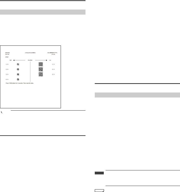
3-10 Batch Setting Code
This section describes the quick setup code.
Quick Setup Code
Users can print the settings specified with AutoID Network Navigator as 2D code and read the code with the SR-750 Series to change all the settings at once. When printing the quick setup code, use the AutoID Network Navigator quick setup code printing function.
Since the settings of the SR-750 Series can be changed by reading the quick setup code, you can easily change the settings even in a location where a computer cannot be used.
Print image
Point |
|
When reading the quick setup code with the high-resolution type |
|
|
|
|
|
unit (SR-750HA), you must use a printer with high print quality. |
|
|
When a printer with low print quality is used, the cells in the 2D |
|
|
code may bleed and become unreadable. |
|
|
|
How to read quick setup codes
Use one of the following methods to read the quick setup code
Reading the quick setup code using the TUNE button
1 Press and hold the TUNE button on the SR-750 Series for at least 4 seconds.
When the quick setup code reading operation starts, "C" and "O" are displayed alternately on the multiple LED indicator of the SR-750 main unit.
2 Read the quick setup code.
According to the code reading status, values displayed on the multiple LED indicator of the SR-750 main unit change.
3 When all quick setup codes are read, "d" is displayed on the multiple LED indicator of the SR-750 main unit.
4 Press the TUNE button once briefly to finish the quick setup code reading operation.
•While reading the quick setup code, the TRG BUSY and MODE BUSY outputs turn ON.
•To cancel the quick setup code reading operation, press the TUNE button once briefly.
When "F" is displayed on the multiple LED display, press the TUNE button once briefly again.
Sending the quick setup code reading commands
Send the quick setup code reading command (RCON) to read the quick setup code.
1 Send the "RCON" command from the control device.
When the SR-750 Series receives the command normally, it returns "OK, RCON", and "C" and "0" are displayed alternately on the multiple LED indicator of the SR-750 main unit.
2 Read the quick setup code.
According to the code reading status, values displayed on the multiple LED indicator of the SR-750 main unit change.
3 When all quick setup codes are read, "d" is displayed on the multiple LED indicator of the SR-750 main unit.
4 Send the "RCOFF" command from the control device.
When the SR-750 Series receives the command normally, it returns "OK, RCOFF", and the quick setup code reading operation finishes. (After the setting is reflected, "d" on the multiple LED goes off.)
•While reading the quick setup code, the TRG BUSY and MODE BUSY outputs turn ON.
•To cancel the quick setup code reading operation, send the "RCOFF" command.
3-11 Code quality verification function
This section describes the Code quality verification function.
Code quality verification function for the SR-750 Series
The Code quality verification function evaluates the level (High/Low) of total grade based on the verification result output and the set threshold by verifying the 2D code scanned with the SR-750 Series according to the marking quality evaluation specified by a third-party institution.
The SR-750 Series provides the following 2D code verifications according to the Code quality verification standards.
Standards |
Description |
|
|
This is the 2D code marking quality evaluation standard |
|
ISO/IEC15415 |
established by International Organization for Standardization. |
|
|
This is mainly used to evaluate 2D codes printed on labels. |
|
|
|
|
|
This is the DPM (Direct Part Marking) 2D code marking quality |
|
|
evaluation standard established by Automatic Identification |
|
ISO/IEC TR 29158 |
Manufacturers. |
|
(AIM DPM-1-2006) |
This is based on ISO/IEC15415. |
|
|
This was also standardized by International Organization for |
|
|
Standardization in 2011. |
|
|
|
|
|
This is the DataMatrix code marking quality evaluation |
|
SAE AS9132 |
standard established by SAE (Society of Automotive |
|
|
Engineers) and used by the aerospace industry. |
|
|
|
|
|
This is the DataMatrix code marking quality evaluation |
|
SEMI T10-0701 |
standard established by SEMI (Semiconductor Equipment and |
|
Materials International) and printed on semiconductor-related |
||
|
||
|
materials. |
|
|
|
 Important Note that this Code quality verification function is designed to evaluate marking quality of the standards-compliant 2D codes of the images scanned with the SR-750 Series, but cannot be used as an official 2D code verification device.

 Reference When you select ISO/IEC15415, you can perform code quality verification of standalone PDF 417 and Micro PDF codes. For information on the verification items, see
  "Code Verification of Japanese Pharmaceutical Drugs" in the "SR-750 Series Additional Functions Manual."
E SR-750 UM |
20 |
Code quality verification function settings
This section describes the setting method of the Code quality verification function and the setting items.
Setting method for the Code quality verification function
To use the Code quality verification function, you need to enable the verification settings you wish to use.
(1)Setting using the AutoID Network Navigator.
Press the "Code quality verification" button on the "Operation" tab in the Settings view, and then check the desired verification standard.
(2)Setting using the setup commands
Send commands that enable the verification functions you wish to use.
 "8-3 Details of Configuration Commands - Reading operation setting (Page 77)"
Point |
|
When the Code quality verification function is enabled, the decode |
||
|
|
|
|
|
|
|
time becomes longer than when it is disabled. |
||
|
|
Perform calibration after enabling the Code quality verification |
||
|
|
function or set the decode timeout period required for reading. |
||
|
|
Use the tact measurement test mode to confirm there is no |
||
|
|
problem with reading time for operation. |
||
|
|
( |
|
"3-4 Test Mode" (Page 12)) |
|
|
|
||
|
|
|
|
|
Append Code quality verification result data
To append the Code quality verification result data, the additional data setting and data format setting are required.
Additional data setting
Select "Operation" - "Additional data" on the "Table" tab in the Settings view, and then set verification results you wish to append as data to "Enable".
 "5-4 Details of Settings View - [Table] tab (Page 43 or later)"
 "3-11 Code quality verification function - Verification items description (Page 21 or later)"
Data format setting
Make the setting relating to the data format.
Set the following three items. |
|
• Select expression of grades |
: Set the grade indication of the verification |
|
result to either Alphabet or Numeric. |
|
(ISO/IEC15415 and ISO/IEC TR 29158 |
|
(AIM DPM-1-2006) only) |
• Append detailed verification result : Set whether to append verification items of
|
each standard to the total grade. |
|
(ISO/IEC15415, ISO/IEC TR 29158 (AIM |
|
DPM-1-2006) and SAE AS9132 only) |
• Append values |
: Set whether to append evaluation values of |
|
each verification item used for verification |
|
result evaluation. |
|
(ISO/IEC15415, ISO/IEC TR 29158 (AIM |
|
DPM-1-2006) and SAE AS9132 only) |
 "7-2 Data Communication Format (Page 63)"
Code quality verification function Evaluation standard
Evaluation by the Code quality verification function is made for the total evaluation grade.
Evaluation standards are as follows.
ISO/IEC15415, ISO/IEC TR 29158 (AIM DPM-1-2006)
High: Verification result >= Threshold value
Low: Verification result < Threshold value
SAE AS9132
High: Verification result = Pass
Low: Verification result = Fail
 Important SEMI T10-0701 does not offer total evaluation grade and cannot make evaluations.
This means that functions that can be used after evaluation cannot be used with SEMI T10-0701.
Functions that can use evaluation results of the Code quality verification function
STABLE terminal output, UNSTABLE terminal output
STABLE terminal output......... This is output when the total evaluation grade is the threshold value or more.
UNSTABLE terminal output ... This is output when the total evaluation grade is less than the threshold value.
( "3-6 Multi-I/O Function (Page 14)")
Saving images of unstable reading
When the total evaluation grade is less than the threshold value, scanned images are saved according to the setting (If the FTP transmission is set, images are sent to the connection destination.).
( "3-7 Image Saving Function (Page 16)")
Silent mode
When the total evaluation grade is more or less than the threshold value, data communication can be restrained using the silent mode.
( "3-8 Silent Mode (Page 18)")
Point |
|
When multiple verifications are in process, these functions |
|
|
|
|
|
operate in priority to the result which is less than the threshold |
|
|
value. |
|
|
|
Note when using the Code quality verification function
Code quality verification results may change according to the setting of the parameter bank for scanning. If the color or contrast of the 2D code and background change, consider preparing the parameter bank setting used as standard and performing the Code quality verification using the setting.
Verification items description
ISO/IEC 15415
|
Decode success/failure |
DEC (Decode) |
|
Description |
Evaluates whether decoding is possible or not. |
|
|
|
|
|
|
Calculation |
― |
― |
|
formula |
|||
|
|
||
|
|
|
|
Criterion |
― |
|
|
Symbol contrast |
SC (Symbol Contrast) |
|
Evaluates the difference between the |
|
Description |
maximum brightness value (Rmax) and |
|
minimum brightness value (Rmin) in the code |
|
|
|
|
|
|
area. |
|
Calculation |
SC = (Rmax-Rmin)/255 |
|
Rmax : Maximum brightness value |
|
|
formula |
|
|
Rmin : Minimum brightness value |
|
|
|
|
|
|
|
|
|
A : more than 0.70 |
|
|
B : 0.55 to 0.70 |
|
Criterion |
C : 0.40 to 0.55 |
|
|
D : 0.20 to 0.40 |
|
|
F : less than 0.20 |
|
|
|
|
21 |
E SR-750 UM |
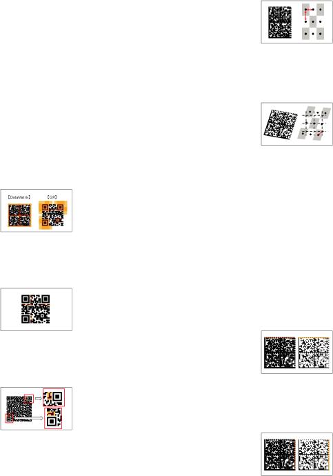
|
Modulation |
MOD (Modulation) |
Description |
Evaluates the variation degree in cell |
|
brightness |
|
|
|
|
|
|
|
|
|
Each cell's MOD = 2 ½ (abs (R-GT)/SC) |
|
Calculation |
R : Brightness value |
― |
formula |
GT : Binarization threshold value |
|
|
SC : Symbol contrast |
|
|
|
|
Criterion |
― |
|
|
Reflectance margin |
RM (Reflectance Margin) |
||
|
Evaluates the variation degree in cell |
|
||
Description |
brightness with black and white of the correct |
|
||
|
cell considered. |
|
||
|
|
|
|
|
|
[White cell] |
|
|
|
|
R >= GT → MARGIN = 2 ½ (R-GT)/SC |
|
||
|
R < GT → MARGIN = 0 |
|
||
|
[Black cell] |
|
― |
|
Calculation |
R < GT → MARGIN = 2 ½ (GT-R)/SC |
|||
|
||||
formula |
R >= → MARGIN = 0 |
|
||
|
MARGIN : Margin of each cell |
|
||
|
R |
: Brightness value |
|
|
|
GT |
: Binarization threshold value |
|
|
|
SC |
: Symbol contrast |
|
|
|
|
|
|
|
Criterion |
|
― |
|
|
|
Fixed pattern damage |
FPD (Fixed Pattern Damage) |
|
Evaluates the degree of the fixed pattern |
|
Description |
damage (area on the right) dependent on the |
|
|
code type. |
|
|
|
|
Calculation |
― |
|
formula |
|
|
|
|
|
|
|
|
Criterion |
― |
|
|
|
|
|
Format information damage |
FID |
|
(Format Information Damage) |
|
|
|
|
Description |
Evaluates the format information damage |
|
degree of QR code. |
|
|
|
|
|
|
|
|
Calculation |
― |
|
formula |
|
|
|
|
|
|
|
|
Criterion |
― |
|
|
|
|
|
|
|
|
Version information damage |
VID |
|
(Version Information Damage) |
|
|
|
|
|
Evaluates the version information damage |
|
Description |
degree of QR code (Model 2, version 2 and |
|
|
later versions). |
|
|
|
|
Calculation |
― |
|
formula |
|
|
|
|
|
|
|
|
Criterion |
― |
|
|
|
|
|
|
Axial nonuniformity |
AN (Axial Nonuniformity) |
Description |
Evaluates the distortion degree in vertical and |
|
|
horizontal size of the code. |
|
||
|
|
||
|
|
|
|
|
AN = abs (Xavg = Yavg)/((Xavg = Yavg)/2) |
|
|
Calculation |
|
Xavg : Average cell size in horizontal |
|
|
direction |
|
|
formula |
|
|
|
|
Yavg : Vertical cell size in horizontal |
|
|
|
|
|
|
|
|
direction |
|
|
|
|
|
|
A : less than 0.06 |
|
|
|
B : |
0.06 to 0.08 |
|
Criterion |
C : |
0.08 to 0.10 |
|
|
D : |
0.10 to 0.12 |
|
|
F : |
more than 0.12 |
|
|
Grid nonuniformity |
GN (Grid Nonuniformity) |
|
Description |
Evaluates the maximum position slip of each |
|
|
cell |
|
|
|
|
|
|
|
|
|
|
|
Calculation |
GN = Hmax/X |
|
|
Hmax : Maximum position slip amount |
|
||
formula |
|
||
X |
: Cell size |
|
|
|
|
||
|
|
|
|
|
A : less than 0.38 |
|
|
|
B : 0.38 to 0.50 |
|
|
Criterion |
C : 0.50 to 0.63 |
|
|
|
D : 0.63 to 0.75 |
|
|
|
F : more than 0.75 |
|
|
|
|
|
|
|
Unused error correction |
UEC |
|
|
(Unused Error Correction) |
||
|
|
|
|
Description |
Evaluates the ratio of error correction unused |
|
|
at the time of decoding. |
|
||
|
|
||
|
|
|
|
|
UEC = 1.0 - ((e + 2t)/(d - p)) |
|
|
|
e |
: Number of code words that cannot be |
|
Calculation |
|
read |
|
formula |
t |
: Number of error code words |
|
|
d |
: Number of error corrected code words |
― |
|
p |
: Number of error detected code words |
|
|
|
|
|
|
A : more than 0.62 |
|
|
|
B : 0.50 to 0.62 |
|
|
Criterion |
C : 0.37 to 0.50 |
|
|
|
D : 0.25 to 0.37 |
|
|
|
F : less than 0.25 |
|
|
|
|
Print growth (horizontal) |
PGH |
|
|
(Print Growth Horizontal) |
|
|
|
|
|
Description |
Evaluates the mark cell growth in the |
|
|
horizontal direction. |
|
||
|
|
||
|
|
|
|
|
(D - 0.5)/0.15 |
|
|
Calculation |
|
D : On the horizontal clock pattern |
|
formula |
|
Ratio of the number of pixels of mark |
|
|
|
cell |
|
|
|
|
|
|
A |
: -0.50 to 0.50 |
|
|
B |
: -0.70 to -0.50 or 0.50 to 0.70 |
|
Criterion |
C : -0.85 to -0.70 or 0.70 to 0.85 |
|
|
|
D : -1.00 to -0.85 or 0.85 to 1.00 |
|
|
|
F |
: less than -1.00 or more than 1.00 |
|
|
|
|
|
|
|
Print growth (vertical) |
PGV (Print Growth Vertical) |
Description |
Evaluates the mark cell growth in the vertical |
|
|
direction. |
|
||
|
|
||
|
|
|
|
|
(D - 0.5)/0.15 |
|
|
Calculation |
|
D : On the vertical clock pattern |
|
formula |
|
Ratio of the number of pixels of mark |
|
|
|
cell |
|
|
|
|
|
|
A |
: -0.50 to 0.50 |
|
|
B |
: -0.70 to -0.50 or 0.50 to 0.70 |
|
Criterion |
C |
: -0.85 to -0.70 or 0.70 to 0.85 |
|
|
D |
: -1.00 to -0.85 or 0.85 to 1.00 |
|
|
F |
: less than -1.00 or more than 1.00 |
|
|
|
|
|
E SR-750 UM |
22 |
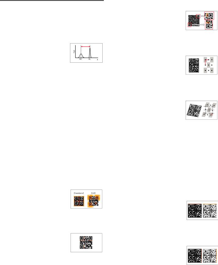
ISO/IEC TR 29158 (AIM DPM-1-2006)
|
Decode success/failure |
DEC (Decode) |
|
Description |
Evaluates whether decoding is possible or not. |
|
|
|
|
|
|
Calculation |
― |
― |
|
formula |
|||
|
|
||
Criterion |
― |
|
|
|
|
|
|
|
|
Cell contrast |
CC (Cell Contrast) |
|
Evaluates the difference between the average |
|
||
Description |
brightness value of bright cell (ML) and |
|
||
|
average brightness value of dark cell (MD). |
|
||
|
|
|
||
|
CC = (ML - MD)/ML |
|
||
Calculation |
|
ML |
: Average brightness value of bright |
|
|
|
cell |
|
|
formula |
|
|
|
|
|
MD |
: Average brightness value of dark |
|
|
|
|
|
||
|
|
|
cell |
|
|
|
|
||
|
A : more than 0.30 |
|
||
|
B : |
0.25 to 0.30 |
|
|
Criterion |
C : |
0.20 to 0.25 |
|
|
|
D : |
0.15 to 0.20 |
|
|
|
F : |
less than 0.15 |
|
|
|
|
|
|
|
|
Cell modulation |
CM (Cell Modulation) |
|
Description |
Evaluates the variation degree in cell |
|
|
brightness |
|
||
|
|
||
|
|
|
|
|
[White cell] |
|
|
|
CM = (R - GT)/(ML - GT) (When R ≥ GT) |
|
|
|
[Black cell] |
|
|
Calculation |
CM = (GT- R)/(GTMD) (When R < GT) |
― |
|
formula |
R |
: Brightness value |
|
|
GT : Binarization threshold value |
|
|
|
ML |
: Average brightness value of bright cell |
|
|
MD : Average brightness value of dark cell |
|
|
|
|
|
|
Criterion |
|
― |
|
|
|
|
|
|
Reflectance margin |
RM (Reflectance Margin) |
||
|
Evaluates the variation degree in cell |
|
||
Description |
brightness with black and white of the correct |
|
||
|
cell considered. |
|
||
|
[White cell] |
|
|
|
|
R >= MARGIN = (R-GT)/(ML-GT) |
|
||
|
R < GT → MARGIN = 0 |
|
||
|
[Black cell] |
|
― |
|
Calculation |
R < GT→MARGIN = (GT-R)/(GT-MD) |
|||
|
||||
formula |
R >= → MARGIN = 0 |
|
||
|
MARGIN : Margin of each cell |
|
||
|
R |
: Brightness value |
|
|
|
GT |
: Binarization threshold value |
|
|
|
CC |
: Cell contrast |
|
|
|
|
|
|
|
Criterion |
|
― |
|
|
|
|
|
|
|
|
Fixed pattern damage |
FPD (Fixed Pattern Damage) |
|
Evaluates the degree of the fixed pattern |
|
Description |
damage (area on the right) dependent on the |
|
|
code type. |
|
Calculation |
― |
|
formula |
|
|
|
|
|
|
|
|
Criterion |
― |
|
|
|
|
|
Format information damage |
FID |
|
(Format Information Damage) |
|
|
|
|
Description |
Evaluates the format information damage |
|
degree of QR code. |
|
|
|
|
|
|
|
|
Calculation |
― |
|
formula |
|
|
|
|
|
|
|
|
Criterion |
― |
|
|
|
|
|
Version information damage |
VID |
|
(Version Information Damage) |
|
|
|
|
|
Evaluates the version information damage |
|
Description |
degree of QR code (Model 2, version 2 and |
|
|
later versions). |
|
|
|
|
Calculation |
― |
|
formula |
|
|
|
|
|
|
|
|
Criterion |
― |
|
|
|
|
|
|
Axial nonuniformity |
AN (Axial Nonuniformity) |
Description |
Evaluates the distortion degree in vertical and |
|
|
horizontal size of the code. |
|
||
|
|
||
|
|
|
|
|
AN = abs (Xavg - Yavg)/((Xavg + Yavg)/2) |
|
|
Calculation |
|
Xavg : Average cell size in horizontal |
|
|
direction |
|
|
formula |
|
|
|
|
Yavg : Vertical cell size in horizontal |
|
|
|
|
|
|
|
|
direction |
|
|
|
|
|
|
A : less than 0.06 |
|
|
|
B : |
0.06 to 0.08 |
|
Criterion |
C : |
0.08 to 0.10 |
|
|
D : |
0.10 to 0.12 |
|
|
F : |
more than 0.12 |
|
|
|
|
|
|
Grid nonuniformity |
GN (Grid Nonuniformity) |
|
Description |
Evaluates the maximum position slip of each |
|
|
cell |
|
|
|
|
|
|
|
|
|
|
|
Calculation |
GN = Hmax/X |
|
|
Hmax : Maximum position slip amount |
|
||
formula |
|
||
X |
: Cell size |
|
|
|
|
||
|
|
|
|
|
A : less than 0.38 |
|
|
|
B : 0.38 to 0.50 |
|
|
Criterion |
C : 0.50 to 0.63 |
|
|
|
D : 0.63 to 0.75 |
|
|
|
F : more than 0.75 |
|
|
|
|
|
|
|
Unused error correction |
UEC |
|
|
(Unused Error Correction) |
||
|
|
|
|
Description |
Evaluates the ratio of error correction unused |
|
|
at the time of decoding. |
|
||
|
|
||
|
|
|
|
|
UEC = 1.0 - ((e + 2t)/(d - p)) |
|
|
|
e |
: Number of code words that cannot be |
|
Calculation |
|
read |
|
formula |
t |
: Number of error code words |
|
|
d |
: Number of error corrected code words |
― |
|
p |
: Number of error detected code words |
|
|
|
|
|
|
A : more than 0.62 |
|
|
|
B : 0.50 to 0.62 |
|
|
Criterion |
C : 0.37 to 0.50 |
|
|
|
D : 0.25 to 0.37 |
|
|
|
F : less than 0.25 |
|
|
|
|
|
|
|
|
Print growth (horizontal) |
PGH |
|
|
(Print Growth Horizontal) |
|
|
|
|
|
Description |
Evaluates the mark cell growth in the |
|
|
horizontal direction. |
|
||
|
|
||
|
|
|
|
|
(D - 0.5)/0.15 |
|
|
Calculation |
|
D : On the horizontal clock pattern |
|
formula |
|
Ratio of the number of pixels of mark |
|
|
|
cell |
|
|
|
|
|
|
A |
: -0.50 to 0.50 |
|
|
B |
: -0.70 to -0.50 or 0.50 to 0.70 |
|
Criterion |
C : -0.85 to -0.70 or 0.70 to 0.85 |
|
|
|
D : -1.00 to -0.85 or 0.85 to 1.00 |
|
|
|
F |
: less than -1.00 or more than 1.00 |
|
|
|
|
|
|
|
Print growth (vertical) |
PGV (Print Growth Vertical) |
Description |
Evaluates the mark cell growth in the vertical |
|
|
direction. |
|
||
|
|
||
|
|
|
|
|
(D - 0.5)/0.15 |
|
|
Calculation |
|
D : On the vertical clock pattern |
|
formula |
|
Ratio of the number of pixels of mark |
|
|
|
cell |
|
|
|
|
|
|
A |
: -0.50 to 0.50 |
|
|
B |
: -0.70 to -0.50 or 0.50 to 0.70 |
|
Criterion |
C |
: -0.85 to -0.70 or 0.70 to 0.85 |
|
|
D |
: -1.00 to -0.85 or 0.85 to 1.00 |
|
|
F |
: less than -1.00 or more than 1.00 |
|
|
|
|
|
23 |
E SR-750 UM |

3-12 Duplicate reading prevention interval reset
The duplicate read prevention function is equipped with the Multi1 reading mode not to read codes again that have been read once. The working time of this duplicate reading prevention function is set by the duplicate reading prevention interval. Two types of the duplicate reading prevention interval reset operation have been prepared with the SR-750 Series.
Types of the duplicate reading prevention interval reset
Two types of the duplicate reading prevention interval reset
•Reset when a code is read.
•Do not reset during duplicate reading prevention interval.
This section describes each operation.
Reset when a code is read.
The duplicate reading prevention function works for one data most recently read. If different codes are read, the duplicate reading prevention interval is reset and the duplicate reading prevention function works for the newly read code data. The duplicate reading prevention interval count starts at the timing when the last code is read.
Timing chart
Timing input
(1) |
(1) |
(2) |
(1) |
(2) |
(2) |
Code
Duplicate reading prevention
Duplicate reading prevention interval
(1) |
(2) |
(1) |
(2) |
(2) |
Data communication
•When reading is successful, reading continues using the successful bank until a reading error occurs.
•If codes with the same contents are read in series, adjust the passing time longer than the time set with the duplicate reading prevention interval (setting range: 100 to 25500 ms). Codes with different contents can be read in series.
•The timing to start measuring the duplicate reading prevention interval is when the code that was read is outside the field of vision.
Do not reset during duplicate reading prevention interval.
The duplicate reading prevention function works for all codes read within the set duplicate reading prevention interval from when the timing input was done and the first code is read. The duplicate reading prevention function works again when the next code is read after the duplicate reading prevention interval finishes.
Timing chart
Timing input
(1) |
(2) |
(1) |
(3) |
(2) |
(1) |
(2) |
(2) |
Code
Duplicate reading prevention
Duplicate reading prevention interval
(1) |
(2) |
(3) |
(1) |
(2) |
Data communication
•Regardless of reading success or reading error, codes are read alternating parameter banks.
•Amount of data memorized during the duplicate reading prevention interval: Up to 160 codes, total of 10 Kbytes
 Important If multiple codes in the same type are seen in the field of view at the same time, take one of the following methods.
•Prepare multiple parameter banks with the read length restricted, and make the setting so the parameter banks are switched for each code.
•Prepare multiple parameter banks with the decoding area
restricted, and make the setting so the parameter banks are switched for each code.
*When Multi read (setting within 1 parameter bank) is set to Enable, if the code data that was read once matches with any of the multiple read code data in 1 scan, not all code data read in the scan are not output.
3-13 Edit data function/Edit image file name function
With the edit data function, read data can be edited into a desired data format. With the edit image file name function, when sending image files to upper ranks via FTP, the image file names can be edited into desired file names.
The edit data function and edit image file name function can do the following.
Edit data (Basic)
•Four arithmetic operations (add, subtract, multiply and divide)
•Conditional branching
•Adding arbitrary characters
•Extracting and combining arbitrary digits
Edit data (Advanced)
Various types of data can be built using four arithmetic operations, conditional branching, etc. from appended data information, etc.
[Example]
• Code rotation angle (Calculated from top coordinates)
Edit image file name
•Time stamp*
•Append read data
 Important • The edit image file name function is available only for images sent via FTP.
This does not function for images saved in RAM and ROM.
• This does not support quick setup codes.
*When using the time stamp, enable the SNTP function of SR-750 and connect to the SNTP server.
(For SNTP setting items, refer to Page 48.)
Procedure for setting the edit data function and edit image file name function
The edit data function and the edit image file name function can be used by sending the file which contains the program of Script to SR-750 and enabling the "Use script file" setting.
Setting procedure
[1] Creating the script file |
[2] Changing the script |
[3] Transferring the script file |
|
execution setting |
|
[1] Creating the script file
Create the script file (FmtSet.lua) and write the program using a text editor such as notepad.exe.
* For programming method, refer to "SR-D100/750 Series Script Reference".
E SR-750 UM |
24 |
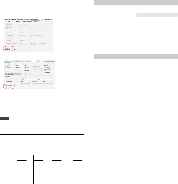
[2] Changing the script execution setting
Using the AutoID Network Navigator, set the script execution setting of the SR750 Series to "Enable".
This must be set for the edit data function and the edit image file name function respectively.
[Edit data function - Script execution setting item]
[Edit image file name function - Script execution setting item]
[3] Transferring the script file
Transfer the script file (FmtSet.lua) to the SR-D100 Series. Following are the transfer methods.
•Sending configuration of AutoID Network Navigator
•Transferring only the script file from the AutoID Network Navigator terminal
•Transferring using the Fileview software
•Transferring using the FTP
 Important When transferring the script file using the Fileview software or the FTP, set the file name to "FmtSet.Lua".
Script file reflection timing
Even if the script file is in operation, transfer is possible each time by using the FTP. In this case, the reflection timing of the script program is from the timing ON after file transfer.
Timing chart
Timing input
Script file |
|
A |
|
|
|
B |
|
|
|
|
|
transfer |
|
|
|
|
|
|
|
|
|
|
|
|
|
|
|
|
|
|
|
|
|
|
|
Data |
|
|
|
A |
|
|
|
A |
|
B |
|
Image file name |
|
|
|
|
|
|
|
|
|
|
|
Handing of the script file when settings are changed, etc.
This section describes how to handles the script file when restoring to the default settings or using the changeover function.
|
|
Operation contents |
FmtSet.lua |
|
AutoID Network Navigator "Retrieve |
Receives with the configuration file at the |
|||
|
|
|
Configuration" |
same time. |
|
|
|||
AutoID Network Navigator "Send |
Sends with the configuration file at the same |
|||
|
|
|
Configuration" |
time. |
|
|
|||
AutoID Network Navigator "Default Settings" |
Remains. |
|||
|
|
|
||
|
Send or delete by FileView |
Transmission and deletion possible from PC. |
||
|
|
|||
Reading quick setup codes |
Remains. |
|||
|
|
|
|
|
Send |
|
|
SAVE |
Remains. |
|
|
|
|
|
|
|
LOAD |
Remains. |
|
command |
|
|||
|
|
|
||
|
DFLT |
Remains. |
||
|
|
|
||
|
|
|
|
|
When executing the script file - status confirmation command
Obtaining the script processing time
Send command |
SCPTIME |
Response |
OK, SCPTIME, now=AAus, max=BBus, min=CCus |
AA:Returns the most recent script processing time.
BB:Returns the maximum value of the processing time.
CC:Returns the minimum value of the processing time.
•Returns the processing time of script executed after power ON.
Script debug setting
Send command SCPDBG, n
Response |
OK, SCPDBG |
n= 0: |
Script debug OFF |
n=1: |
Script debug ON |
•This sets whether to output debug from the script file to the command port or not.
•Setting the debug ON executes print(str) and outputs data.
Obtaining the script error results
Send command |
SCPERR |
Response |
OK, SCPERR, mmmmmmmmmmmmmmmmmmmmmmmmmmmmmm |
|
mm… : Script error character string |
• This returns the details of script error.
Obtaining the script version
Send command SCPVER
Response |
OK, SCPVER, mmmm, nnnn |
mm...: |
Script library version |
nn… : |
FmtSet.lua version |
|
(Only when FmtSet.lua exists and the version is defined) |
•FmtSet.Lua version is the value stored in variable name "SCPVERSION" within the FmtSet.Lua file.
•This returns the script library version and the FmtSet.lua version.
•If the script library does not exist, the error code 12 is returned.
*The script library is a library file to use the edit data function and the edit image file name function.
25 |
E SR-750 UM |
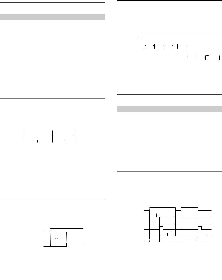
4-1 Reading Operations
This section describes the reading conditions of the SR-750 Series.
Steps of Read Operation
The SR-750 Series follow the read sequence below:
(1) |
Trigger input processing |
: Trigger input is verified and light is |
|
|
controlled. |
(2) |
Scanning + image transfer |
: The image is scanned within the specified |
|
|
exposure time and the image is transferred. |
(3) |
Decoding processing |
: The captured image is filtered and the code |
|
|
is processed (decoded). |
(4) |
Data communication processing : The decoded results are output as data. |
|
Since (2) and (3) above are based on the settings registered with the parameter banks, operation is repeated using alternate banks until a code is read or the trigger input is turned off.
Specify the following operations for the above processing:
• Timing Mode |
Specify from level trigger or one-shot trigger. |
• Data Transmission |
Select "Send after read" or "Send after timing OFF". |
• Read mode |
Specify from Single, Multi1, Multi 2 or burst. |
Timing Chart
This section describes the steps of basic operations of the SR-750 Series. Operating conditions are as follows:
• Timing Mode |
|
|
|
|
: Level trigger |
|
|
|
|
|
|
|
|
||||
• Timing to send data |
: Send after read |
|
|
|
|
|
|
|
|
||||||||
• Read mode |
|
|
|
|
: Single |
|
|
|
|
|
|
|
|
||||
• Parameter bank |
|
|
|
|
: Set 2 banks, alternate mode |
|
|||||||||||
|
|
|
|
|
|
|
|
|
|
|
|
|
|
|
|
||
(1) Trigger input |
|
|
|
|
Operation of parameter bank 1 |
Operation of parameter bank 2 |
|
||||||||||
(2) Scanning + |
|
|
|
||||||||||||||
|
|
|
|
|
|
|
|
|
|
|
|
|
|
|
|||
|
|
|
|
|
|
|
|
|
|
|
|
|
|
|
|||
A |
B |
|
C |
|
|
B |
C |
|
|
|
|
|
|||||
image transfer |
|
|
|
|
|
|
|
|
|
||||||||
|
|
|
|
|
|
|
|
|
|
|
|
|
|
|
|||
(3) Decoding |
|
|
|
|
|
|
|
|
|
|
|
|
|
|
|
||
|
|
|
|
|
D |
|
|
|
F |
|
|
|
|||||
processing |
|
|
|
|
|
|
|
|
|
|
|
|
|||||
|
|
|
|
|
|
|
|
|
|
|
|
|
|
|
|||
(4) Data |
|
|
|
|
|
|
|
|
|
|
|
|
|
|
|
||
|
|
|
|
|
|
|
|
|
|
|
|
Read data |
|
|
|||
communication |
|
|
|
|
|
|
|
|
|
|
|
|
|
|
|
||
|
|
|
|
|
|
|
|
|
|
|
|
|
|
|
|||
A:Input time constant + Scan delay time
B:Exposure time set for each parameter bank (max. 9.99 ms)
C:Image transfer time (approx. 16 ms)
D:Decode time out period set for each parameter bank (Max. 2550 ms)
F:Decoding time when reading is successful
•The above is the image when reading is successful. For read error, B, C and D are repeated continuously and read error data is output when the trigger input is turned off.
Scan delay time
When the entry timing of the target to be conveyed is shifted from the input timing of the timing sensor, set the "scan delay time".
This makes it possible to start scanning under optimum read conditions by setting the delay for the timing at which emission of light of the SR-750 begins.
•The time can be set between 0 and 255 ms in increments of 1 ms (Default: 0 ms).
•Set the scan delay period for the parameter bank.
Trigger input
Input time |
|
Scan delay |
constant |
|
time |
Scanning
Internal bank retry count
When the internal bank retry count is set, 1 parameter bank is repeated. When decoding cannot be complete within the specified internal bank retry count, operation to switch to the next parameter bank is possible.
If reading operation becomes unstable due to vibration of the workpiece, setting the internal bank retry count enables stable reading.
Timing Chart
(1)Trigger input
(2) Parameter bank 1 |
Scanning + |
|
Scanning + |
|
Scanning + |
|
Scanning + |
|
|
|
|
|
|
|
|
|
|
||||||||
operation |
|
|
|
|
|
|
|
|
|
|
|
|
|
|
|
||||||||||
|
|
|
decoding |
|
decoding |
|
decoding |
|
|
decoding |
|
|
|
|
|
|
|
|
|
|
|||||
Internal bank retry |
|
|
|
|
|
|
|
|
|
|
|
|
|
|
|
|
|
|
|
|
|
|
|
||
count = a |
|
0 times |
|
1 time |
|
2 times |
|
|
a times |
|
|
|
|
|
|
|
|
|
|||||||
(3) Parameter bank 2 |
|
|
|
|
|
|
|
|
|
|
|
|
|
|
|
|
|
|
|
|
|
|
|
||
|
|
|
|
|
|
|
|
|
|
|
|
|
Scanning + |
|
Scanning + |
|
|
|
|
|
|||||
operation |
|
|
|
|
|
|
|
|
|
|
|
|
|
|
|
|
|
|
|
|
|||||
|
|
|
|
|
|
|
|
|
|
|
|
|
|
decoding |
|
|
decoding |
|
|
|
|
|
|||
Internal bank retry |
|
|
|
|
|
|
|
|
|
|
|
|
|
|
|
|
|
|
|
|
|
|
|
||
count = b |
|
|
|
|
|
|
|
|
|
|
|
|
|
0 times |
|
|
1 time |
|
|
b times |
|
||||
•The internal bank retry count can be set within the range from 0 to 32. (Factory setting: 0)
•If a large number is set for the internal bank retry count and multiple parameter banks are registered, reading time per time will become longer. Secure sufficient reading time so that reading can be stable.
4-2 Timing Mode
This section describes the timing mode of the SR-750 Series.
Type of timing mode
The SR-750 Series provides the following 2 types of timing mode.
•Level trigger
•One-shot trigger
For the remainder of this section, assume the following settings are used:
• Read mode |
: Single |
• Data Transmission |
: Send after read |
• Output terminal settings |
OUT1 = OK |
|
OUT2 = NG + ERROR |
|
OUT3 = TRG BUSY |
*Output terminal settings  "3-6 Multi-I/O Function (Page 14)"
*For convenience sake, the timing chart does not indicate the input pulse width + scan delay time.
Level trigger
When the trigger input turns on, the SR-750 Series turns on the illumination to start scanning.
When a code is read successfully, it stops illumination and sends the data.
If the SR-750 Series fails to read a code, it stops illumination when the trigger input turns off and sends a reading error.
Timing Chart
(When reading is successful) |
(When reading failed) |
Trigger input
Code
Scanning + decoding
Data communication
OK/NG/ERROR output |
OK/NG |
ERROR |
TRG BUSY output
•Set the trigger input so it stays ON from the reading start time until reading end time.
•The illumination of the SR-750 Series turns on after the trigger input has been activated for the specified input time constant.
•The input time constant for the trigger input can be changed to 1 ms, 2 ms, or 10 ms.
•The RS-232C data communication time can be obtained using the following equation:
Data length + (1: When parity is used) + Start/stop bits
Baud rate × (Number of digits of data to be sent + Number of characters of header and terminator)
•The ON time for the OK/NG/ERROR output can be set within the range of 10 to 2550 ms (Default: 500 ms).
E SR-750 UM |
26 |
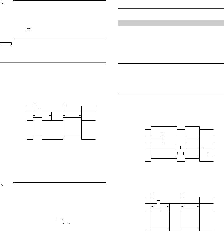
Point |
When a code is read at an interval shorter than the specified |
||
|
|
|
|
|
output ON time, the OK/NG/ERROR output turns off even if the |
||
|
output ON time of the previous output signal has not elapsed, and |
||
|
a new output signal turns on for the specified output ON time. If |
||
|
output terminal operations of the same type occur successively |
||
|
(such as OK→OK), the previous output signal turns off for 10 ms, |
||
|
and then the new output signal turns on. |
||
|
Refer to |
|
"Page 15 Function and Operation of the Output |
|
|
||
Terminals (OUT1, OUT2 and OUT3)".

 Reference The TRG BUSY output turns on from the time the trigger input turns on to the time the code reading is complete or the trigger input is turned off.
One-shot trigger
When the SR-750 Series detects that the trigger input is on, it turns on the lighting for the specified one-shot trigger duration to scan a code.
When a code is read successfully, it stops illumination and sends the data. Other operations are the same as those for the level trigger.
Use the one-shot trigger if the ON time of the trigger input is extremely short or if you want to fix the read time.
Timing Chart
|
(When reading is successful) |
(When reading failed) |
||||||||||
Trigger input |
|
|
|
|
|
|
||||||
Code |
|
|
|
|
|
|
||||||
|
One-shot trigger duration |
One-shot trigger duration |
||||||||||
Scanning + decoding |
|
|
|
|
|
|
|
|
||||
Data communication |
|
|
|
|
|
|
|
|
|
|
||
|
|
|
|
|
|
|
|
|
|
|
|
|
OK/NG/ERROR output |
|
|
|
|
|
|
|
|
|
|||
|
|
|
OK/NG |
|
|
|
|
ERROR |
|
|||
TRG BUSY output |
|
|
|
|
|
|
||||||
•When the trigger input stays on for the specified input time constant, the illumination of the SR-750 Series turns on and the scanning begins. When the reading is complete, the illumination stops.
•The input time constant for the trigger input can be changed to 1 ms, 2 ms, or 10 ms.
•The one-shot trigger duration can be changed within the range of 100 to 25500 ms.
•If the SR-750 Series fails to read a code within the one-shot trigger duration, it stops illumination and outputs a reading error.
•Other operations and precautions are the same as those for the level trigger.
Point |
|
The ON state of the trigger input is recognized after the input stays |
||||||
|
|
|
|
|
|
|
|
|
|
|
on for at least the specified input time constant. |
||||||
|
|
The OFF state of the trigger input is recognized after the input |
||||||
|
|
stays off for at least the specified input time constant. |
||||||
|
|
Consequently, when the line speed is fast and fast pulse signals |
||||||
|
|
are used as trigger input signals, be careful to make the ON/OFF |
||||||
|
|
time of the pulse signals longer than the specified input time |
||||||
|
|
constant. |
|
|
|
|
|
|
|
|
|
|
a |
||||
|
|
Trigger input |
|
|
|
|
|
|
|
|
|
|
|
|
|
|
|
|
|
|
|
|
|
|
|
|
|
|
|
|
b |
|
|
|
|
|
|
|
|
|
|
|
|
|
|
|
Trigger input time constant = when a, if a becomes larger than b, |
||||||
|
|
the OFF state of the trigger input is not recognized. |
||||||
|
|
When a ≤ b, the ON/OFF state of the timing signal can be |
||||||
|
|
recognized. |
|
|
|
|
|
|
|
|
|
|
|
|
|
|
|
4-3 Data Transmission Timing
This section describes the data transmission timing of the SR-750 Series.
Type of data transmission timing
The SR-750 Series offers the following 2 options for outputting the read data and OK/NG/ERROR signals:
•Send after reading
•Send after timing OFF
Select the appropriate type for your application.
*For the sake of simplicity, Input time constant + Scan delay time is not shown in the timing chart.
Send after reading
The SR-750 Series outputs read data and an OK/NG signal as soon as it completes reading codes. If the SR-750 Series fails to read a code, it outputs a read error code and an ERROR signal at the point when the timing signal turns off. The timing charts are the same as those shown in "Timing Mode".
 "4-2 Timing Mode (Page 26)"
Send after timing OFF
When "Send after timing OFF" is selected, the SR-750 Series outputs read data and an OK/NG/ERROR signal at the next timing point for the specified trigger type. Use this type to output data and output signals with the same timing.
Timing Chart for the level trigger
When the trigger input turns off, read data and OK/NG/ERROR signal are output.
(When reading is successful) |
(When reading failed) |
Trigger input
Code
Scanning + decoding
Data communication
OK/NG/ERROR output |
OK/NG |
ERROR |
TRG BUSY output
•When a code is read successfully, the read operation stops.
•The TRG BUSY output continues until the trigger input turns off.
Timing Chart for the one-shot trigger
When the specified one-shot trigger duration elapses, the read data and OK/NG/ ERROR signal are output.
|
(When reading is successful) |
(When reading failed) |
|||||||||
Trigger input |
|
|
|
|
|
|
|||||
Code |
|
|
|
|
|
|
|||||
|
|
One-shot trigger duration |
|
One-shot trigger duration |
|||||||
Scanning + decoding |
|
|
|
|
|
|
|
|
|||
|
|
|
|
|
|
|
|||||
Data communication |
|
|
|
|
|
|
|
|
|||
|
|
|
|
|
|
|
|
|
|
|
|
OK/NG/ERROR output |
|
|
|
|
|
|
|
||||
|
|
|
|
OK/NG |
|
|
|
ERROR |
|
||
TRG BUSY output |
|
|
|
|
|
|
|||||
•When a code is read successfully, the read operation stops.
•The TRG BUSY output continues until the one-shot trigger duration elapses.
27 |
E SR-750 UM |
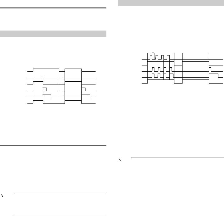
4-4 Read Mode
The SR-750 Series offers 4 types of read modes. Select the appropriate type for your application. For most applications, use "Single read mode".
*For the sake of simplicity, Input time constant + Scan delay time is not shown in the timing chart.
Single read mode
In this mode, the SR-750 Series reads a single code while the trigger input is turned on once, and then outputs data.
Scanning will not begin again until the timing input is first turned off, then back on again.
Timing Chart
(When reading is successful) (When reading failed)
Trigger input
Code
Scanning + decoding
Data communication
OK/NG/ERROR output |
OK/NG |
ERROR |
TRG BUSY output
*The above timing chart shows the case where "Level trigger" and "Send after reading" are selected.
•In single read mode, the data transmission timing can be selected from "Send after reading" or "Send after timing off".
•The timing mode can be selected from "Level trigger" or "One-shot trigger".
•Scan interval is automatically set so that decoding processing can be implemented efficiently.
 "4-1 Reading Operations (Page 26)"
Multiple Code Reading in Single Read Mode
Normally, the single read mode is used to read 1 code from 1 timing input signal. When the following read setting conditions are specified, multiple codes within the field of view can be read with 1 timing input signal.
Setting "Multi read" in the code detail settings
When "Multi read" is selected in the code detail settings, multiple codes can be read in 1 reading operation.
•Use the AutoID Network Navigator or setting command to set.
•The number of codes for multiple readings can be set between 2 and 16
•When "Allow reduced detection count" is selected, the reading is considered successful if at least 1 code is read successfully.
Point |
• In this setting, multiple codes of different types cannot be read |
|
|
|
in 1 read action. |
•Codes are output in order starting from the code coordinates above the upper scan screen (if the height is the same, from the left).
•The output data format is as follows:
Header |
The 1st data |
, |
The 2nd data |
, |
··· |
Terminator |
|
|
|
|
|
|
|
,= Inter delimiter: Can be changed with setting (Default = "," (0x2C))
Multi 1 Read Mode
In this mode, the SR-750 Series reads multiple codes in succession while the trigger input is turned on once.
In Multi 1 read mode, the SR-750 Series sends out data and outputs an OK signal every time it reads 1 code (or an OK/NG signal when preset data is registered). The SR-750 continues to scan while the trigger input is on even if no code is present. ERROR will only be output if no code is read after the trigger signal is turned off.
Timing Chart
|
|
(When reading is successful) |
(When reading failed) |
|||||||
|
|
|
|
|
|
|
|
|
||
|
|
|
|
|
Duplicate reading |
|
|
|
||
Trigger input |
|
|
|
|
prevention interval |
|
|
|
||
Code |
|
|
|
|
|
|
|
|
|
|
Scanning + decoding |
|
|
|
|
|
|
|
|
|
|
Data communication |
|
|
|
|
|
|
|
|
|
|
OK/NG/ERROR output |
OK |
OK |
OK |
OK |
|
ERROR |
||||
/ |
/ |
/ |
/ |
|
|
|||||
|
|
NG |
NG |
NG |
NG |
|
|
|||
TRG BUSY output
•The SR-750 Series reads codes in succession for the following duration: Level trigger : While the trigger input is turned on
One-shot trigger : During the specified one-shot trigger duration
•The duplicate reading prevention operation changes according to the setting of
the duplicate reading prevention interval reset.  "3-12 Duplicate reading prevention interval reset" (Page 24)
•When codes with the same contents are read in succession, adjust the moving speed so that the codes pass at intervals longer than the specified duplicate reading prevention interval (Setting range: 0 to 25500 ms). Codes with different contents can be read at shorter intervals.
•Each time scanning is performed in Multi 1 operation, the laser pointer lights up. The lighting period for the laser pointer is set on "Laser-aimer blinking duration (0 to 990 ms)" and the scanning is not performed during this period.
•The data transmission timing for Multi 1 is "Send after read" only.
•In Multi 1 operation, the availability of the image save function is as follows. Saving images
•Read OK/NG ...Cannot be used
•Error image .....Can be used
Point |
|
When Multi 1 read mode is selected using the AutoID Network |
|
|
|
|
|
Navigator, the decode timeout is set to 500 ms. To shorten the |
|
|
decode timeout period, change the decode timeout setting of each |
|
|
parameter bank manually. |
|
|
|
E SR-750 UM |
28 |
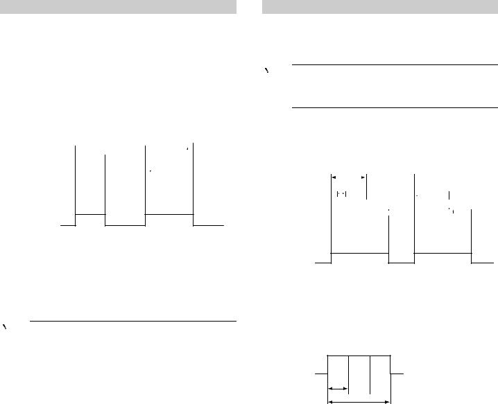
Multi 2 Read Mode
Multi 2 read mode is used to read the codes in the parameter banks with registered settings in order while the trigger input is turned on once.
After reading all codes (max. 10 types) registered with the parameter bank, this function sends the read data in the order of parameter number and outputs OK/NG signals.
If no code is read while the trigger input is turned on or if even one code set for a parameter bank is not read, the SR-750 Series sends a reading error and outputs an ERROR signal for the unread code in the parameter bank after the trigger input turns off.
Timing Chart
Timing charts when registered with the parameter banks 1, 2 and 4 are as follows:
|
|
(When reading is successful) |
(When reading failed) |
||||||||||||||||||||
|
|
|
|
|
|
|
|
|
|
|
|
|
|
|
|
|
|
|
|
|
|
|
|
Trigger input |
|
|
|
|
|
|
|
|
|
|
|
|
|
|
Read error |
|
|
|
|||||
|
|
|
Parameter bank No. |
|
|
|
|
|
|
|
|
|
|
|
|
|
|
||||||
|
|
|
|
|
|
|
|
|
|
|
|
|
|
|
|
|
|
|
|
|
|
||
Scanning + decoding |
|
|
(1) |
(2) |
(4) |
|
|
|
|
|
(1) |
(2) |
(4) |
(2) |
(2) |
|
|
|
|||||
|
|
|
|
|
|
|
|
|
|
|
|
|
|
|
|
|
|
|
|
|
|
|
|
Data communication |
|
|
|
|
|
|
|
|
|
|
Reading success |
|
|
|
|||||||||
|
|
|
|
|
|
|
|
|
|
|
|
||||||||||||
|
|
|
|
|
|
|
|
|
|
|
|
|
|
|
|
|
|
|
|
|
|
|
|
|
|
|
|
|
|
|
|
|
|
|
|
|
|
|
|
|
|
|
|
|
|||
OK/NG/ERROR output |
|
|
|
|
|
OK/ |
|
|
|
|
|
|
|
|
|
|
|
|
ERROR |
|
|||
|
|
|
|
|
NG |
|
|
|
|
|
|
|
|
|
|
|
|
|
|
|
|
|
|
TRG BUSY output
•The SR-750 Series reads codes in succession for the following duration: Level trigger : While the trigger input is turned on
One-shot trigger : During the specified one-shot trigger duration
•An OK signal is output when all of the codes of the set parameter banks are read.
•An ERROR signal is output when even 1 specified code could not be read.
•Even when there are multiple codes within the reading range, all codes can be read simultaneously.
•Each time scanning is performed in Multi 2 operation, the laser pointer lights up. The lighting period for the laser pointer is set on "Laser-Aim pulse duration (0 to 990 ms)" and the scanning is not performed during this period.
Point |
|
When Multi 1 read mode is selected using the AutoID Network |
|
|
|
|
|
Navigator, the decode timeout is set to 500 ms. To shorten the |
|
|
decode timeout period, change the decode timeout setting of each |
|
|
parameter bank manually. |
|
|
|
Output data format
The following output data format is used for the read data.
|
Read data in |
|
Read data in |
|
|
|
Read data in |
|
Header |
parameter bank |
, |
parameter bank |
, |
... |
, |
parameter bank |
Terminator |
|
No. 1 |
|
No. 2 |
|
|
|
No. 10 |
|
•Each read data is separated with "," (0x2C: Intermediate delimiter).
•The data for the read bar codes is saved in the send buffer of the SR-750 Series once and then is output when all configured banks have been read or the timing input is turned off. The size of the send buffer of the SR-750 Series is 10 KB.
•If reading fails for any of parameter banks 1 to 10 or if the specified code is not found, ERROR is sent as the read data of the corresponding parameter bank number.
Burst Reading Mode
The burst reading mode is a function to repeat scan up to a maximum of 8 times in succession and perform decoding after the scanning is complete.
When, for example, the line speed is fast and accurate positioning is difficult, this function ensures scanning without missing codes by repeating scans only for the period during which the target is expected to pass.
Point |
• The alternate function cannot be used in Burst reading mode. |
|
|
|
Decoding is performed with the specified parameter number. |
•In Burst reading mode, the No. of repeat read attempts setting is ignored.
Timing Chart
The following is the timing chart when the Burst reading mode is used. (Burst scan count: 3)
|
|
|
|
<When reading is successful> |
<When reading failed> |
|
|
|
|
|
|
|||||||||||||||||||||
Trigger input |
|
|
|
|
|
|
|
|
|
|
|
|
|
|
|
|
|
|
|
|
|
|
|
|
|
|
|
|
|
|
|
|
|
No. of burst scans |
|
|
|
|
|
|
|
|
|
|
|
|
|
|
|
|
|
|
|
|
|
||||||||||
Scanning |
|
|
|
|
|
|
|
|
|
|
|
|
|
|
|
|
|
|
|
|
|
|
||||||||||
|
|
|
|
|
|
|
|
|
|
|
|
|
|
|
|
|
|
|
|
|
|
|
|
|
|
|
|
|
|
|
||
|
(1) |
|
|
(2) |
|
(3) |
|
|
|
|
|
|
|
(1) |
|
(2) |
|
(3) |
|
|
|
|
|
|
|
|
|
|||||
|
|
|
|
|
|
|
|
|
|
|
|
|
|
|
|
|
|
|
|
|
|
|
|
|||||||||
|
|
|
Burst scan interval |
|
|
|
|
|
|
|
|
|
|
|
|
|
|
|
|
|
|
|
|
|
|
|||||||
|
|
|
|
|
|
|
|
|
|
|
|
|
|
|
|
|
|
|
|
|
|
|
|
|
||||||||
Decoding |
|
(1) |
(2) |
(3) |
|
|
|
|
|
|
|
|
|
|
(1) |
(2) |
(3) |
|
|
|
|
|
||||||||||
|
|
|
|
|
|
|
|
|
|
|
|
|
|
|
|
|
|
|
|
|
|
|
|
|||||||||
|
|
|
|
|
|
|
|
|
|
|
(Failed) (Failed) (Succeeded) |
|
|
|
|
|
|
|
|
|
|
|
|
|
|
|
|
|||||
|
|
|
|
|
|
|
|
|
|
|
|
|
|
|
|
|
(Failed) (Failed) (Failed) |
|
|
|
|
|
||||||||||
Data communication |
|
|
|
|
|
|
|
|
|
|
|
|
|
|
|
|
|
Burst scan No. |
|
|
|
|
|
|
||||||||
|
|
|
|
|
|
|
|
|
|
|
|
|
|
|
|
|
|
|
|
|
|
|
|
|
|
|||||||
|
|
|
|
|
|
|
|
|
|
|
|
|
|
|
|
|
|
|
|
|
|
|
|
|
|
|
|
|
|
|
||
|
|
|
|
|
|
|
|
|
|
|
|
|
|
|
|
|
|
|
|
|
|
|
|
|
|
|
|
|
|
|
||
OK/NG/ERR LED output |
|
|
|
|
|
|
|
|
|
|
|
|
|
OK/NG |
|
|
|
|
|
|
|
|
|
|
|
ERROR |
|
|
|
|||
|
|
|
|
|
|
|
|
|
|
|
|
|
|
|
|
|
|
|
|
|
|
|
|
|
|
|
|
|
|
|
||
|
|
|
|
|
|
|
|
|
|
|
|
|
|
|
|
|
|
|
|
|
|
|
|
|
|
|
|
|
|
|
|
|
TRG BUSY output
•In Burst reading mode, the scanned data is decoded in the order in which it was obtained.
If decoding fails after the decode timeout period elapses, the decoding is shifted to the next scanned data.
•The data communication is output when the decoding is successful or decoding of all scan data is failed.
The decoding time when decoding succeeds for the third scanned data is as follows:
Decoding Decoding Decoding
failed failed succeede
Burst scan Burst scan Burst scan
No. No. No.
Decoding
(1) (2) (3)
Decode timeout
Decoding time
•If the trigger input turns off with the decoding processing unfinished, reading error occurs. Secure longer time for the trigger input ON than the time calculated by (scan + burst scan interval + decoding timeout time) x burst scan count.
•The data transmission timing for the Burst reading mode is "Send after read" only.
29 |
E SR-750 UM |
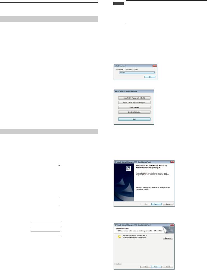
5-1 Installing, Starting, and
Shutting Down
This section describes how to install AutoID Network Navigator as well as how to start and shut down the application.
PC Requirements
Before starting installation, confirm that your PC meets the following requirements:
Supported OSs
•Windows XP (SP3 or higher) 32-bit version
•Windows Vista (Business/Ultimate, SP2 or higher) 32-bit version
•Windows 7 (Professional or higher) 32-bit version/64-bit version
•Windows 8 (Windows RT excluded)
*NET Framework 3.5 SP1 or later must be installed in advance.
*When installing .NET3.5 on Windows 8, the Internet environment is necessary.
*When installing .NET3.5 on Windows 8, operate from the control panel.
Hardware
|
32-bit |
|
64-bit |
Processor |
|
2.0 GHz |
|
System Memory |
1 GB |
|
2 GB |
DVD-ROM Drive |
|
Required for installation |
|
Communication Port |
|
Ethernet port |
|
|
|
|
|
Precautions
•To install AutoID Network Navigator, log on as a user with rights to change the system configuration, such as Administrator or Computer Administrator.
•Quit all active applications before starting the installation. The installation may take longer if antivirus software or other applications are active on the computer.
Trademark
Windows 8/Windows 7/Vista/XP is a registered trademark of Microsoft Corporation in the United States.
Install Method
This section explains installation using the following drive configuration under Windows 7 as an example:
Drive C: Hard disk drive Drive E: DVD-ROM drive
Folder Structure
The folder structure on the master disc is as follows.
disc |
|
|
manual |
|
|
JP |
|
Manual data in PDF format |
||
|
|
|
|
|
||||||
|
|
|
|
|
|
EN |
|
|
|
|
|
|
|
|
|
|
CHT |
|
|
|
|
|
|
|
|
|
|
CHS |
|
|
|
|
|
|
|
|
|
|
DE |
|
|
|
|
|
|
|
|
|
|
|
|
|
|
|
|
|
|
Setup |
|
|
AutoID Launcher.exe |
|
|
|
|
|
|
|
|
|
|
AutoID Launcher.ini |
|
|
|
|
|
|
|
|
|
|
|
|
|
|
|
|
|
|
|
|
|
JP |
|
|
|
|
|
|
|
|
|
|
EN |
|
|
AutoID Network Navigator |
|
|
|
|
|
|
|
CHT |
|
|
Multimonitor |
|
|
|
|
|
|
|
|
|
|
||
|
|
|
|
|
|
CHS |
|
|
FileView |
|
|
|
|
|
|
|
DE |
|
|
|
|
|
|
|
|
|
|
|
|
|
|
|
|
|
|
|
|
|
SetupPrerequisites |
|
|
dotnetfx35.exe |
|
|
|
|
|
|
|
|
|
|
||
|
|
|
|
|
|
|
|
|
setupNF.exe |
|
|
|
|
|
|
|
|
|
|
languagepack |
|
|
|
|
|
|
|
|
|
SR-D100/750/650 Series main unit firmware |
||
|
|
|
firmware |
|
|
|
|
|||
|
|
|
|
|
|
|
||||
|
|
|
|
|
|
|
|
EDS file for EtherNet/IP |
||
|
|
|
EDS |
|
|
|
|
|||
|
|
|
|
|
|
|
||||
|
|
|
|
|
|
|
|
GSDML file for PROFINET |
||
|
|
|
GSDML |
|
|
|
|
|||
|
|
|
|
|
|
|
||||
|
|
|
|
|
|
|
|
Sample program of Visual Basic, C# and C++ |
||
|
|
|
Windows sample program |
|
|
JP |
|
|||
|
|
|
|
|
|
EN |
|
|
|
|
Installation Flow
1 Turn ON the PC and start Windows.
 Important • To install AutoID Network Navigator, log on as a user with rights to change the system configuration, such as Administrator or Computer Administrator.
•Quit all active applications before starting the installation. The installation may take longer if antivirus software or other applications are active on the computer.
2 Insert the "AutoID Network Navigator Master Disc" into the DVDROM drive of the PC.
3 Normally, the AutoRun function of the computer will display the following screen.
To start the installer directly, use Windows Explorer or another method to open the DVD-ROM drive, and double-click "AutoID Launcher.exe" in the Setup folder.
AutoID Launcher will start and select the language of the installer software.
4 The AutoID Network Navigator installer will start.
5 Click "Install .NET Framework 3.5 SP1".
If .NET Framework 3.5 SP1 is already installed in the computer to be used, then the install will automatically exit.
•If .NET Framework 3.5 SP1 is not installed, follow the on-screen instructions to continue with the installation.
6 Click "Install AutoID Network Navigator".
7 Click "Next".
8 Click "Next".
Click on the [Change] button to change to the folder in which the application will be installed.
E SR-750 UM |
30 |
Loading...