


 Loading...
96M11843
Environment Resisting Type
Built-in-amplifier Pressure Sensors
GP-M Series
Instruction Manual
Read this instruction manual before using the product in order to achieve maximum performance.
Keep this instruction manual in a safe place after reading it so that it can be used at any time.
Symbols
In this instruction manual, the following symbols will be used to so that important points can be understood at one glance.
Be sure to read these messages carefully.
|
|
|
|
It indicates a hazardous situation which, if not |
|
|
DANGER |
|
avoided, will result in death or serious injury. |
|
|
|
|
|
|
|
|
|
|
|
|
|
|
It indicates a hazardous situation which, if not |
|
|
WARNING |
|
|
|
|
|
avoided, could result in death or serious injury. |
|
|
|
|
|
|
|
|
|
|
|
|
|
|
|
It indicates a hazardous situation which, if not |
|
|
CAUTION |
|
|
|
|
|
avoided, could result in minor or moderate injury. |
|
|
|
|
|
|
|
|
|
|
|
|
|
NOTICE |
It indicates a situation which, if not avoided, could |
|
|
|
result in product damage as well as property damage. |
||
|
|
|
|
|
|
|
Reference |
It indicates tips for better understanding or useful information. |
|
|
|
|||
|
|
|
|
|
Safety Information for GP-M Series
|
|
|
1. |
Do not use this product for the purpose to |
|
|
|
|
protect a human body or a part of human body. |
|
|
|
2. |
This product is not intended for use as an |
|
|
|
|
explosion-proof product. Do not use this |
|
|
|
|
product in hazardous locations and/or |
|
|
|
|
potentially explosive atmospheres. |
|
|
|
3. |
The GP-M Series is not designed to sanitary |
|
WARNING |
|
||
|
|
|
specifications. Do not use the product for |
|
|
|
|
|
|
|
|
|
|
applications such as drinks, foods, or medical |
|
|
|
|
liquids. |
|
|
|
4. |
Do not use the GP-M Series for applications |
|
|
|
|
requiring safety measures, such as any |
|
|
|
|
nuclear, railroad, aircraft, vehicle, or |
|
|
|
|
playground equipment. |
|
|
|
|
|
2

|
|
|
1. |
You must verify that the GP-M Series is |
|
|
|
|
operating correctly in terms of functionality |
|
|
|
|
and performance before the start and |
|
|
|
|
operation of the GP-M Series. |
|
CAUTION |
|
|
|
|
|
2. |
We recommend that you take all the necessary |
|
|
|
|
||
|
|
|
|
safety measures to avoid any damage in the |
|
|
|
|
unlikely event of a problem occurring. |
|
|
|
3. |
Do not use the GP-M Series with corrosive liquids. |
|
|
|
|
|
1.We cannot guarantee the functions and/or performance in the event that the product is used outside the standards of the specification, or if the product is modified.
2.When using our product in combination with
NOTICE |
another product, based on such factors as |
|
|
|
conditions of use and surrounding |
|
environment, sometimes functions and |
|
performance may not be fully realized. In such |
|
a case, use after adequate examination. |
Precautions on Regulations and Standards
CE Marking
KEYENCE Corporation has confirmed that this product complies with the essential requirements of the applicable EC Directives, based on the following specifications. Be sure to consider the following specifications when using this product in the Member States of European Union.
z EMC Directive (2004/108/EC)
• Applicable standards EMI: EN61326-1, Class A EMS: EN61326-1
Remarks
These specifications do not give any guarantee that the end-product with this product incorporated complies with the essential requirements of EMC Directive.
The manufacturer of the end-product is solely responsible for the compliance on the end-product itself according to EMC Directive.
3

CSA Certificate
GP-M Series complies with the following CSA and UL standards and has been certified by CSA.
• Applicable standard CAN/CSA C22.2 No.61010-1 UL61010-1
Be sure to consider the following specifications when using this product as a product certified by CSA.
•Overvoltage category: 1
•Use this product under pollution degree 2.
•Use this product at the altitude of 2000 m or less.
•Indoor use only.
•Use CSA/UL certified power supply that provides Class 2 output as defined in the CEC (Canadian Electrical Code) and NEC (National Electrical Code), or CSA/ULcertified power supply that has been evaluated as a Limited Power Source as defined in CAN/CSA-C22.2 No. 60950-1/UL60950-1.
•Do not use the GP-M Series for poizonous fluid.
Caution when handling
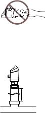
1.When detecting the temperature of the fluid, the housing of the product will be hot, and there is
CAUTION |
the danger of a burn injury. Do not touch the |
|
metal housing while the product is in operation. |
||
|
2.The screw part of the main unit is sharp, take care to avoid injury.
1.Do not drop or hit the device, and avoid any other large shock to the device.
2.Do not use a sharply pointed object to press the setting keys.
NOTICE 3. If the detection portion is pushed with sharp thing, damage may occur to the detection
surface. Also, for devices where the measuring range is low, the detection portion is thin and easy to break. Touch as little as possible.
4

Precautions for wiring
1.Do not modify or disassemble unnecessarily. It may cause electric shock or improper operation.
2.Do not work on the wiring with bare hands. Even if the power is OFF, electric charge may remain and cause electric shock.
3.Do not work on the pipe work or wiring with
CAUTION |
|
wet hands. It may cause electric shock. |
|
4. |
When wiring, confirm the pin position. |
5. |
Use the GP-M Series within the rated range. |
|
|
|
The GP-M Series is a sensor that uses a DC |
|
|
(direct current) power source. Do not apply |
|
|
alternating current or other power supplies. Do |
|
|
not use a load that exceeds the allowable limit. |
1.Use an insulated stabilizing supply for the power supply.
2.Do not pull strongly on the cable.
3.Ensure that the cable tip is not submersed in
NOTICE |
water during wiring work. |
4.Isolate the cable from power supply lines or power lines.
5.Isolate the cable as far as possible from any source of noise.
Other precautions
1.The power ON reset time for the GP-M Series is 2 seconds after power is turned on. Do not use outputs from the sensor during this period.
2.Initial drift may occur after supplying power to
NOTICE |
the GP-M Series. To detect a minute difference |
|
in the pressure, let the GP-M Series warm up |
|
for approximately 15 to 30 minutes. |
3.Do not bring a strong magnet or magnetic field close to the main body of the GP-M Series.
5
4.Do not remove the seal of the air hole of the GP-M001/M010/M025. It will no longer be waterproof.
5.When condensation occurs, it may become impossible to make measurements, or, damage may occur. Take measures such as the following to prevent condensation.
|
• Ensure that the ambient temperature is the same |
|
NOTICE |
or lower than the fluid temperature. |
|
• Remove moisture via air conditioning |
||
|
•Separate the sensor 30 cm or more from the cooling pipes using the connector pipe.
6.When conducting maintenance, use a soft brush so as not to damage items such as the detection surface or the O-Ring.
7.When replacing the O-Ring, clean all of the debris from the surface that will be in contact with the O-Ring.
Checking the Packed Items
|
|
|
|
|
|
|
|
|
|
|
|
|
|
|
|
|
|
|
|
|
|
|
|
|
|
|
|
|
|
|
|
|
|
|
|
|
|
|
|
|
|
|
|
|
|
|
GP-M001/M010/M025 |
|
|
|
|
|
|
|
|
|
|
|
|
|
|
|
|
|
|
|
|
|
|
|
|
|
|
|
|
|
|||||||||||||||
|
|
|
|
|
|
|
|
|
|
|
|
|
|
|
|
|
|
|
|
|
|
|
|
|
|
|
|
|
|
||||||||||||||||
|
Sensor x 1 |
|
|
|
O-Ring x 1 |
|
|
|
|
|
|
|
|
|
|
|
|
|
|
|
|||||||||||||||||||||||||
|
|
|
|
|
|
|
|
|
|
|
|
|
|
|
|
|
|
|
|||||||||||||||||||||||||||
|
|
|
|
|
|
|
|
|
|
|
|
|
|
|
|
|
|
|
|||||||||||||||||||||||||||
|
Instruction manual x 1 |
|
|
|
(OP-87287) |
|
|
|
|
|
|
|
|
|
|
|
|
|
|
|
|||||||||||||||||||||||||
|
|
|
|
|
|
|
|
|
|
|
|
|
|
|
|
|
|
|
|||||||||||||||||||||||||||
|
|
|
|
|
|
|
|
|
|
|
|
|
|
|
|
|
|
|
|||||||||||||||||||||||||||
|
|
|
|
|
|
|
|
|
|
|
|
|
|
|
|
|
|
|
|
|
|
|
|
|
|
|
|
|
|
|
|
|
|
|
|
|
|
|
|
|
|
|
|
|
|
|
|
|
|
|
|
|
|
|
|
|
|
|
|
|
|
|
|
|
|
|
|
|
|
|
|
|
|
|
|
|
|
|
|
|
|
|
|
|
|
|
|
|
|
|
|
|
GP-M100/M250/M400 |
|
|
|
|
|
|
|
|
|
|
|
|
|
|
|
|
|
|
|
|
|
|
|
|
|
|
|
|
|
|||||||||||||||
|
|
|
|
|
|
|
|
|
|
|
|
|
|
|
|
|
|
|
|
|
|
|
|
|
|
|
|
|
|
||||||||||||||||
|
Sensor x 1 |
|
|
|
O-Ring set x 1 |
|
|
|
|
|
|
|
|
|
|
|
|
|
|
|
|||||||||||||||||||||||||
|
|
|
|
|
|
|
|
|
|
|
|
|
|
|
|
|
|
|
|||||||||||||||||||||||||||
|
|
|
|
|
|
|
|
|
|
|
|
|
|
|
|
|
|
|
|||||||||||||||||||||||||||
|
Instruction manual x 1 |
|
|
|
(OP-87288) |
|
|
|
|
|
|
|
|
|
|
|
|
|
|
|
|||||||||||||||||||||||||
|
|
|
|
|
|
|
|
|
|
|
|
|
|
|
|
|
|
|
|||||||||||||||||||||||||||
|
|
|
|
|
|
|
|
|
|
|
|
|
|
|
|
|
|
|
|||||||||||||||||||||||||||
|
|
|
|
|
|
|
|
|
|
|
|
|
|
|
|
|
|
|
|
|
|
|
|
|
|
|
|
|
|
|
|
|
|
|
|
|
|
|
|
|
|
|
|
|
|
6

Name and Function of Each Part
1 |
4 Operating light (output 1) |
Connector |
5 Operating light |
for input |
(output 2) |
cable use 


2 |
6 |
7 DOWN |
Clasp |
UP button |
button (V) |
|
(U) |
8 MODE button |
3Air hole*
*Only for the GP-M001/M010/M025
Piping/Installation
Piping
•Use the adapter for matching with the diameter of the piping.
•When using a replacement adapter, attach the O-Ring included with the Main Unit to the groove of the G3/4 female screw part. (Refer to the diagram below)
GP-M001/M010/M025 GP-M100/M250/M400
O-Ring
 Adapter
Adapter |
Adapter |
•Inquire to us when connecting the pipes directly using the GP-M Series with a G3/4 female screw.
•The body may be rotated horizontally to 330°. When rotating, hold the clasp in place with something such as a wrench.
7
Precautions when installing
z Attaching the coupling
The recommended tightening torque when installing the adapter to the main body of the sensor is 20 N•m. It is recommended to apply grease to the G3/4 screw part in order to avoid scorching.
z Grounding of metal parts
The metal parts of the main body, the internal circuits 0 V are insulated.
z Other precautions
• Regardless of whether the power of the device is ON or OFF, do not touch the main part of the pressure detector, if the if the pressure detector is touched, damage may occur due to static electricity.
•If using a non-conductive liquid such as oil, and plastic piping are used, the risk of an offset change will become greater. In such a case, it is recommended to ground the metal housing.
•In the case that noise causes malfunction, grounding the metal housing may improve performance.
•After installation, conduct an atmospheric correction by making the applied pressure the same as regular room pressure. (Refer to page 10)
•When there is condensation,
separate the sensor from cooling pipe by at least 30 cm using the connecting pipe.
30 cm or more |
Cooling pipe
8
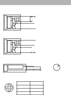
Wiring, Output Diagram
Output diagram
z When choosing an NPN output
Main circuit
Overcurrent protection circuit
1
4 (Output 1)
2 (Output 2)*
3
 10 to 30 VDC
Load |
Load |
|
|
|
|
 0 V
0 V
* When choosing the function of output 2 QWV (control output) only. z When choosing a PNP output
Main circuit
Overcurrent protection circuit
1
4 (Output 1)
2 (Output 2)*
3
 10 to 30 VDC
|
|
|
Load |
Load |
|
 0 V
0 V
* When choosing the function of output 2 QWV (control output) only.
Analog output diagram |
Pin |
Main circuit |
Analog current |
2 4 to 20 mA* |
3 |
2 |
output circuit |
Analog input device |
4 |
||
|
1 |
|||
|
|
3 |
0 V |
|
|
|
|
|
*When Choosing #P.) of the Function of Output 2 only.
M12 Connector Cable (Optional) Pin Position
1 |
|
1 |
Brown |
2 |
2 |
White |
|
4 |
3 |
Blue |
|
3 |
|
||
|
|
4 |
Black |
9
Loading...