


 Loading...
96M0761 FEATURES
Separate Amplifier Type
Pressure Sensor
AP-40(P) Series
Instruction Manual
PART NAMES AND FUNCTIONS
■ Amplifier
AUTO key |
|
|
In auto-tuning mode, use |
|
|
this key to detect pres- |
|
|
sure. In measurement |
A |
|
mode, press this key for 2 |
||
|
||
seconds or more to adjust |
|
|
the zero-point. |
|
SET key
Use this key to display or change preset values.
Output indicator 2
(Green LED)
Screw hole
Use this hole to bolt the
mounting
bracket with Top side a hexagonal
socket bolt.
Front side
Output indicator 1
(Red LED)
 AP-41
AP-41
UP/DOWN key
Use these keys to set output modes, or to change preset values or units.
Display unit label
 Connector port
Insert the sensor head connector.
Connector cover
Bottom side
■ Sensor head |
Connector |
Sensor head
AP-41(M)/43/44
●Separate amplifier-type pressure sensor
Faster response is achieved by reducing the total capacity of piping.
●Two-color, LED digital display
High-intensity, two-color LED ensures high visibility. Four types of display patterns are selectable.
●Chattering prevention function
The instantaneous drops in base pressure due to the activation of a large-bore ejector or other devices can be canceled. This eliminates the need for preparing a sequence program.
●Automatic sensor head recognition function
When the power is turned on, the amplifier checks the sensor head connection automatically. A recognized sensor head type appears green on the display for 0.5 seconds.
●Industry's smallest and lightest sensor head (AP-41M)
This sensor head with half the volume of conventional models weighs only 4.8 g, enabling flexible mounting.
●Zero-shift function (AP-40Z)
The current pressure value can be reset to 0 at any time in order to prevent measurements from being affected by fluctuations in base pressure.
Amplifier accessories |
|
|
||
• |
Instruction |
• |
Mounting |
• Mounting |
|
manual: 1 |
|
bracket A: 1 |
bracket B: 1 |
• |
Hexagonal |
|
|
|
|
socket bolt: 2 |
|
|
|
Reference:
DIN-rail mounting or panel mounting is also available. (Optional brackets are required.)
Sensor head accessories
Spare connector: 1
Hexagonal socket bolts
Mini-wrench: 1
(for AP-41M only)
Piping options
OP-33155 |
M5 |
Screw pipe joint |
M5 |
|
(Male) |
M5 |
|
OP-33156 T-shaped quickrelease joint (ø4)
OP-42220
T-shaped quick release joint (M3)
M5 
 ø4
ø4
M3
 ø4
ø4
OP-35388
PT 1/8
conversion |
Rc(PT)1/8 |
|
|
|
|
|
|
joint |
|
|
M5 |
OP-33157 |
|
|
|
T-shaped |
|
|
|
quick-release |
M5 |
ø6 |
|
joint (ø6) |
|
||
|
|
|
|
M5
OP-33158 Reducer
ø6 
1
MOUNTING
■ AP-40/40Z/40P
As shown in the figure with "Amplifier accessories" on page 1, attach the mounting bracket to the amplifier with hexagonal socket bolts. The mounting bracket can be attached laterally according to the location.
CAUTION
To avoid breakage, limit the tightening torque for the hexagonal socket bolt to 0.3 N•m.
■ AP-41(M)/43/44
CAUTION |
Limit the tightening torque for the screw hole of |
|
the sensor head to 0.3 N•m. |
||
|
■ Zero-point adjustment
At normal atmospheric pressure (1 atm.), press A for at least 2 seconds in measurement mode. The display changes to “----”, then to “0”. The zero adjustment function can be used when the pressure is within ±5% of F.S.
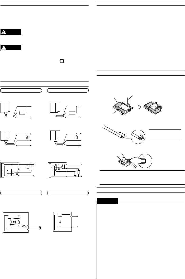
CONNECTIONS AND INPUT/OUTPUT CIRCUIT
AP-40/40Z
■ Connections
• Drive current load
Brown
12 to 24 VDC
Black or white
Load
Blue
0 V
•Input to voltage input equipment
Brown |
12 to 24 VDC |
|
|
|
4.7 k Ω |
Black or white |
Voltage output |
|
|
Blue |
0 V |
|
AP-40P
• Drive current load
Brown
12 to 24 VDC
Black or white
Load
Blue
0 V
•Input to voltage input equipment
Brown |
12 to 24 VDC |
|
|
|
4.7 k Ω |
Black or white |
Voltage output |
|
|
Blue |
0 V |
|
■ Input/output circuit
• Output circuit |
• Output circuit |
circuit |
|
|
Brown |
Load |
12 to 24 VDC |
circuit |
|
|
Brown |
|
|
12 to 24 VDC |
|
|
|
Load |
|
|
|
|
|
||||
sensorPressuremain |
currentOver |
protectioncircuit |
|
|
0 V |
sensorPressuremain |
currentOver |
protectioncircuit |
Black |
Load |
Load |
0 V |
|
|
|
Black |
|
|
|
|
|
|
|
|
|
|
|
|
(Control output 1) |
|
|
|
|
(Control output 2) |
|
|
||
|
|
|
White |
|
|
|
|
|
White |
|
|
|
|
|
|
(Control output 2) |
|
|
|
|
|
|
|||
|
|
|
Blue |
|
|
|
|
|
Blue |
|
|
|
BASIC OPERATION
Basic operation (See also "ADJUSTMENT" on page 4.) <Example>
● Checking the suction condition
1.Select F-3 (2-independent mode) and return to the measurement mode.
Refer to the setting in "Operation Mode" on the left-hand side of page 4.
2.Enter the target pressure value (A) and return to the measurement mode. (You can specify another target pressure value (b).)
Refer to the setting in "Preset Value Input Mode" on the right-hand side of page 4.
3.Start detection.
● Base pressure control
1.Select F-4 (Window mode) and return to the measurement mode.
Refer to the setting in "Operation Mode" on the left-hand side of page 4.
2.Enter the upper (H) and lower (L) limit values of the allowable pressure and return to the measurement mode.
Refer to the setting in "Preset Value Input Mode" on the right-hand side of page 4.
3.Start detection.
ATTACHING A SPARE CONNECTOR
Use the spare connector to change the length of the sensor head cable. Cables as long as 10 m can be used.
1. If the connector cover is fitted into the connector body, open the cover.
Connector body
2. Lift the end of the cover.
Connector cover |
1. Widen the gap. |
|
2.Cut a cable to the appropriate length and strip off the sheath for approximately 25 mm from the end.
Approx. |
|
|
25 mm |
Approx. |
Note: It is not necessary |
|
25 mm |
to remove the sheath of |
|
|
|
|
|
the core wire. |
3.Insert the cables into the proper holes as deep as possible. Then, press the connector cover into the body with pliers.
Reference:
1  Orange
2  Brown
Brown
3  Blue
Blue
4  Gray
Gray
Note 1: Do not allow the cable to protrude from the other end of the connector cover.
Note 2: Ensure that the cables are inserted as far as they will go. If the inserted length is insufficient, the press-fitting fails.
AP-40Z (Z type only)
•Input circuit (Zero-shift input)
Zero-shift input resets the display to “0” at the rising edge of the signal.
Pressuresensor |
circuitmain |
12 to 24 VDC |
|
11 k Ω |
Blue |
||
|
|
3.3 k Ω |
|
|
|
|
Pink |
AP-40/40P (40/40P type only)
• Analog output circuit
Pressuresensor |
Protection |
Pink |
Analog |
circuitmain |
|
|
|
|
circuit |
|
output (+) |
|
|
|
|
|
|
Blue |
0 V |
|
|
|
SAFETY PRECAUTIONS
Be sure to follow the instructions below to avoid malfunctions.

 CAUTION
■ Connection
•When using a commercially available switching regulator, be sure to ground the frame ground terminals.
•Isolate the sensor’s wiring from power lines or high-voltage lines; otherwise, the sensor may malfunction due to noise interference.
•The amplifier becomes hot or breaks down due to improper wiring.
•The press-fitting is available only once for each sensor head connector.
■ Notice about CE marking
•Attach the ferrite core (OP-87505) if you extend a sensor head cable/ amplifier power cable to 3 m or more to use. (Attachment position: within 100 mm from the amplifier unit of a power cable, Number of turns: 2)
■ Other
•Do not use the AP-40 Series for the detection of corrosive gases or liquid.
•Do not insert any objects, such as wires, from the pressure port. The pressure-sensing element may break, resulting in malfunctions.
•Do not press the front panel keys with a pointed object.
•The AP-40 Series does not have an explosion-proof structure.
Do not use it for the detection of flammable gases.
2
Loading...