


 Loading...
Illustrated Parts Manual
Models
1532E2
1932E2
2032E2
2632E2
2646E2
3246E2
3120738
September 24, 2013
REVISION LOG
February 1998 - Original Issue Of Manual (Edited to 0010549 Revision 3)
July 1998 - Revised Manual (Edited to 0010549 Revision 10)
February 26, 1999 - Revised Manual (Edited to 0010549 Revision 18)
May 1, 1999 - Revised Manual (Edited to 0010549 Revision 21) August 30, 1999 - Revised Manual (Edited to 0010549 Revision 24) January 1, 2000 - Revised Manual (Edited to 0010549 Revision 31) June 15, 2000 - Revised Manual (Edited to 0010549 Revision 33) October 31, 2000 - Revised Manual (Edited to 0010549 Revision 35) January 30, 2001 - Revised Manual (Edited to 0010549 Revision 40) July 2, 2001 - Revised Manual (Edited to 0010549 Revision 45) October 29, 2001 - Revised Manual (Edited to 0010549 Revision 49) May 23, 2002 - Revised Manual (Edited to 0010549 Revision 57) September 20, 2002 - Revised Manual (Edited to 0010549 Revision 61) February 26, 2003 - Revised Manual (Edited to 0010549 Revision 65) June 26, 2003 - Revised Manual (Edited to 0010549 Revision 70)
June 29, 2004 - Revised Manual (Edited to 0010549 Revision 73) April 7, 2005 - Revised Manual (Edited to 0010549 Revision 73) September 9, 2008 - Revised Manual
November 30, 2011 - Revised Manual
September 24, 2013 - Revised Manual
3120738 |
A |
REVISION LOG
B |
3120738 |
TABLE OF CONTENTS
FIGURE NO. |
TITLE |
PAGE NO. |
SECTION 1 - FRAME . . . . . . . . . . |
. . . . . . . . . . . . . . . . . . . . . . . . . . . . . . . . . . . . . . . . . |
. . .1-1 |
1-1 WHEEL DRIVE AND STEERING INSTALLATION - 1532E2 & 1932E2 . . . . . . . . . . . . . .1-2 1-2 DRIVE MOTOR ASSEMBLY - 1532E2 & 1932E2 (S/N 90870 to Present) . . . . . . . . . . . . .1-6 1-3 BRAKE INSTALLATION - 1532E2 & 1932E2 . . . . . . . . . . . . . . . . . . . . . . . . . . . . . . . . .1-8 1-4 FRAME AND STEERING INSTALLATION - 2032E2/2632E2/2646E2/3246E2 . . . . . . . .1-10 1-5 WHEEL DRIVE AND BRAKE INSTALLATIONS - 2032E2/2632E2/2646E2/3246E2 . . . .1-14 1-6 DRIVE MOTOR ASSEMBLY - (2032E2/2646E2 S/N 90870 to Present)
(2632E2/3246E2 S/N 90855 to Present). . . . . . . . . . . . . . . . . . . . . . . . . . . . . . . . . . . .1-18 1-7 FRAME MOUNTED COMPONENTS INSTALLATIONS . . . . . . . . . . . . . . . . . . . . . . . . . .1-22
SECTION 2 - GROUND CONTROLS . . . . . . . . . . . . . . . . . . . . . . . . . . . . . . . . . . . . . . . . . .2-1
2-1 HYDRAULIC COMPONENTS INSTALLATIONS - 1532E2/1932E2 . . . . . . . . . . . . . . . .2-2 2-2 HYDRAULIC COMPONENTS INSTALLATIONS - 2032E2/2632E2/2646E2/3246E2 . . .2-6 2-3 VALVE ASSEMBLY - STANDARD CONTROLS MACHINES . . . . . . . . . . . . . . . . . . . . . .2-10 2-4 VALVE ASSEMBLY - PROPORTIONAL CONTROLS MACHINES . . . . . . . . . . . . . . . . . .2-14 2-5 ELECTRICAL COMPONENTS INSTALLATION (LEFT SIDE OF MACHINES WITH
STANDARD CONTROLS) . . . . . . . . . . . . . . . . . . . . . . . . . . . . . . . . . . . . . . . . . . . . . . . .2-18 2-6 ELECTRICAL COMPONENTS INSTALLATION (LEFT SIDE OF MACHINES WITH
PROPORTIONAL CONTROLS) . . . . . . . . . . . . . . . . . . . . . . . . . . . . . . . . . . . . . . . . . . . .2-22 2-7 ELECTRICAL COMPONENTS INSTALLATION (RIGHT SIDE) . . . . . . . . . . . . . . . . . . . .2-26 2-8 BATTERY CHARGER ASSEMBLIES . . . . . . . . . . . . . . . . . . . . . . . . . . . . . . . . . . . . . . . .2-30 2-9 POTHOLE PROTECTION AND TRAY INSTALLATIONS . . . . . . . . . . . . . . . . . . . . . . . . .2-34
SECTION 3 - SIZZOR ARMS . . . . . . . . . . . . . . . . . . . . . . . . . . . . . . . . . . . . . . . . . . . . . . . .3-1
3-1 SCISSOR ARMS INSTALLATION - 1532E2 . . . . . . . . . . . . . . . . . . . . . . . . . . . . . . . . . . .3-2 3-2 SCISSOR ARMS INSTALLATION - 1932E2 . . . . . . . . . . . . . . . . . . . . . . . . . . . . . . . . . . .3-6 3-3 SCISSOR ARMS INSTALLATION - 2032E2 . . . . . . . . . . . . . . . . . . . . . . . . . . . . . . . . . .3-10 3-4 SCISSOR ARMS INSTALLATION - 2632E2 . . . . . . . . . . . . . . . . . . . . . . . . . . . . . . . . . .3-14 3-5 SCISSOR ARMS INSTALLATION - 2646E2 . . . . . . . . . . . . . . . . . . . . . . . . . . . . . . . . . . .3-18 3-6 SCISSOR ARMS INSTALLATION - 3246E2 . . . . . . . . . . . . . . . . . . . . . . . . . . . . . . . . . . .3-22
SECTION 4 - PLATFORM. . . . . . . . . . . . . . . . . . . . . . . . . . . . . . . . . . . . . . . . . . . . . . . . . . .4-1
4-1 |
PLATFORM AND ACCESSORIES INSTALLATION . . . . . . . . . . . . . . . . . . . . . . . . . . . . |
4-2 |
4-2 |
STANDARD HANDRAILS INSTALLATION (1532E2/1932E2) . . . . . . . . . . . . . . . . . . . . . |
4-6 |
4-3 |
FOLDDOWN HANDRAILS INSTALLATION (1532E2/1932E2) . . . . . . . . . . . . . . . . . . . . |
4-10 |
4-4 |
STANDARD HANDRAILS INSTALLATION (2032E2) . . . . . . . . . . . . . . . . . . . . . . . . . . . |
4-14 |
4-5 |
FOLDDOWN HANDRAILS INSTALLATION (2032E2/2632E2) . . . . . . . . . . . . . . . . . . . . |
4-18 |
4-6 |
FOLDDOWN HANDRAILS INSTALLATION (2632E2) . . . . . . . . . . . . . . . . . . . . . . . . . . . |
4-22 |
4-7 |
FOLDDOWN HANDRAILS INSTALLATION (2646E2/3246E2) . . . . . . . . . . . . . . . . . . . . |
4-26 |
4-8 |
PLATFORM CONSOLE BOX ASSEMBLIES (STANDARD CONTROLS MACHINES). . . |
4-30 |
4-9 |
PLATFORM CONSOLE BOX ASSEMBLIES (PROPORTIONAL CONTROLS |
|
|
MACHINES) . . . . . . . . . . . . . . . . . . . . . . . . . . . . . . . . . . . . . . . . . . . . . . . . . . . . . . . . |
4-34 |
4-10 |
CONTROLLER ASSEMBLY (STANDARD CONTROLS MACHINES) . . . . . . . . . . . . . . . |
4-38 |
4-11 |
CONTROLLER ASSEMBLY (PROPORTIONAL CONTROLS MACHINES) . . . . . . . . . . . |
4-40 |
3120738 |
i |
TABLE OF CONTENTS
FIGURE NO. |
TITLE |
PAGE NO. |
SECTION 5 - CYLINDER . . . . . . . . |
. . . . . . . . . . . . . . . . . . . . . . . . . . . . . . . . . . . . . . . . |
. . . 5-1 |
5-1 BRAKE CYLINDER ASSEMBLY. . . . . . . . . . . . . . . . . . . . . . . . . . . . . . . . . . . . . . . . . . . . 5-2 5-2 LIFT CYLINDER COMPONENTS ASSEMBLY (1532E2 & 1932E2) . . . . . . . . . . . . . . . . 5-4 5-3 LIFT CYLINDER COMPONENTS ASSEMBLY (2032E2) . . . . . . . . . . . . . . . . . . . . . . . . . 5-8 5-4 LIFT CYLINDER COMPONENTS ASSEMBLY (2646E2) . . . . . . . . . . . . . . . . . . . . . . . . 5-12 5-5 LIFT CYLINDER COMPONENTS ASSEMBLY (3246E2) . . . . . . . . . . . . . . . . . . . . . . . . 5-16 5-6 STEER CYLINDER ASSEMBLY . . . . . . . . . . . . . . . . . . . . . . . . . . . . . . . . . . . . . . . . . . . 5-20
SECTION 6 - HYDRAULIC. . . . . . . . . . . . . . . . . . . . . . . . . . . . . . . . . . . . . . . . . . . . . . . . . . 6-1
6-1 HYDRAULIC DIAGRAM - 1532E2 & 1932E2 & 2032E2 . . . . . . . . . . . . . . . . . . . . . . . . . 6-2 6-2 HYDRAULIC DIAGRAM - 2646E2 . . . . . . . . . . . . . . . . . . . . . . . . . . . . . . . . . . . . . . . . . . 6-6 6-3 HYDRAULIC DIAGRAM - 3246E2 WITH STANDARD CONTROLS . . . . . . . . . . . . . . . . . 6-8 6-4 HYDRAULIC DIAGRAM - 3246E2 WITH PROPORTIONAL CONTROLS. . . . . . . . . . . . . 6-10 6-5 HYDRAULIC DIAGRAM - 2632E2 WITH STANDARD CONTROLS . . . . . . . . . . . . . . . . . 6-12 6-6 HYDRAULIC DIAGRAM - 2632E2 WITH PROPORTIONAL CONTROLS. . . . . . . . . . . . . 6-14 6-7 HYDRAULIC DIAGRAM LIST . . . . . . . . . . . . . . . . . . . . . . . . . . . . . . . . . . . . . . . . . . . . . . 6-16
SECTION 7 - ELECTRICAL . . . . . . . . . . . . . . . . . . . . . . . . . . . . . . . . . . . . . . . . . . . . . . . . . 7-1
7-1 ELECTRICAL SCHEMATIC (STANDARD CONTROLS MACHINES). . . . . . . . . . . . . . . . 7-2 7-2 ELECTRICAL SCHEMATIC (PROPORTIONAL CONTROLS MACHINES) . . . . . . . . . . . 7-4 7-3 ELECTRICAL COMPONENTS INSTALLATION (STANDARD CONTROLS MACHINES) 7-6 7-4 ELECTRICAL COMPONENTS INSTALLATION (PROPORTIONAL CONTROLS
MACHINE) . . . . . . . . . . . . . . . . . . . . . . . . . . . . . . . . . . . . . . . . . . . . . . . . . . . . . . . . . . 7-12 7-5 ELECTRICAL DIAGRAM LIST . . . . . . . . . . . . . . . . . . . . . . . . . . . . . . . . . . . . . . . . . . . . . 7-18
SECTION 8 - DECALS . . . . . . . . . . . . . . . . . . . . . . . . . . . . . . . . . . . . . . . . . . . . . . . . . . . . . 8-1
8-1 DECALS INSTALLATION - 1532E2 & 1932E2 (COMMON) . . . . . . . . . . . . . . . . . . . . . . 8-2 8-2 DECALS INSTALLATION - 1532E2 & 1932E2 (COUNTRY SPEC) . . . . . . . . . . . . . . . . . 8-6 8-3 DECALS INSTALLATION - 2032E2 & 2632E2 & 2646E2 & 3246E2 (COMMON) . . . . . 8-12 8-4 DECALS INSTALLATION - 2032E2 & 2632E2 & 2646E2 & 3246E2 (COUNTRY SPEC)8-16
SECTION 9 - RECOMMENDED SERVICE PARTS STOCK . . . . . . . . . . . . . . . . . . . . . . . . 9-1 SECTION 10 - SPECIAL OPTIONS . . . . . . . . . . . . . . . . . . . . . . . . . . . . . . . . . . . . . . . . . . . 10-1 SECTION 11 - INDEX . . . . . . . . . . . . . . . . . . . . . . . . . . . . . . . . . . . . . . . . . . . . . . . . . . . . . . 11-1
ii |
3120738 |

SECTION 1 FRAME
TABLE OF CONTENTS
FIGURE |
DESCRIPTION |
PAGE |
|
|
|
1-1 |
Wheel Drive And Steering Installation - 1532E2 & 1932E2 . . . . . . . . . . . . . . . . . . . . . . . . . |
. 1-2. . |
1-2 |
Drive Motor Assembly - 1532E2 & 1932E2 (S/N 90870 to Present) . . . . . . . . . . . . . . . . . . |
. 1-6. . |
1-3 |
Brake Installation - 1532E2 & 1932E2 . . . . . . . . . . . . . . . . . . . . . . . . . . . . . . . . . . . . . . . . . |
1-8. . . |
1-4 |
Frame And Steering Installation - 2032E2/2632E2/2646E2/3246E2 . . . . . . . . . . . . . . . . . . |
. 1-10. . |
1-5 |
Wheel Drive And Brake Installations - 2032E2/2632E2/2646E2/3246E2 . . . . . . . . . . . . . . |
. 1-14. . |
1-6 |
Drive Motor Assembly - (2032E2/2646E2 S/N 90870 to Present) (2632E2/3246E2 |
|
|
S/N 90855 to Present) . . . . . . . . . . . . . . . . . . . . . . . . . . . . . . . . . . . . . . . . . . . . . . . . . . . |
. 1-18. . |
1-7 |
Frame Mounted Components Installations . . . . . . . . . . . . . . . . . . . . . . . . . . . . . . . . . . . . . |
. 1-22. . |
S E C T I O N
1
F
R A M E
3120738 |
1-1 |
S E C T I O N
1
F
R A M E
SECTION 1 FRAME
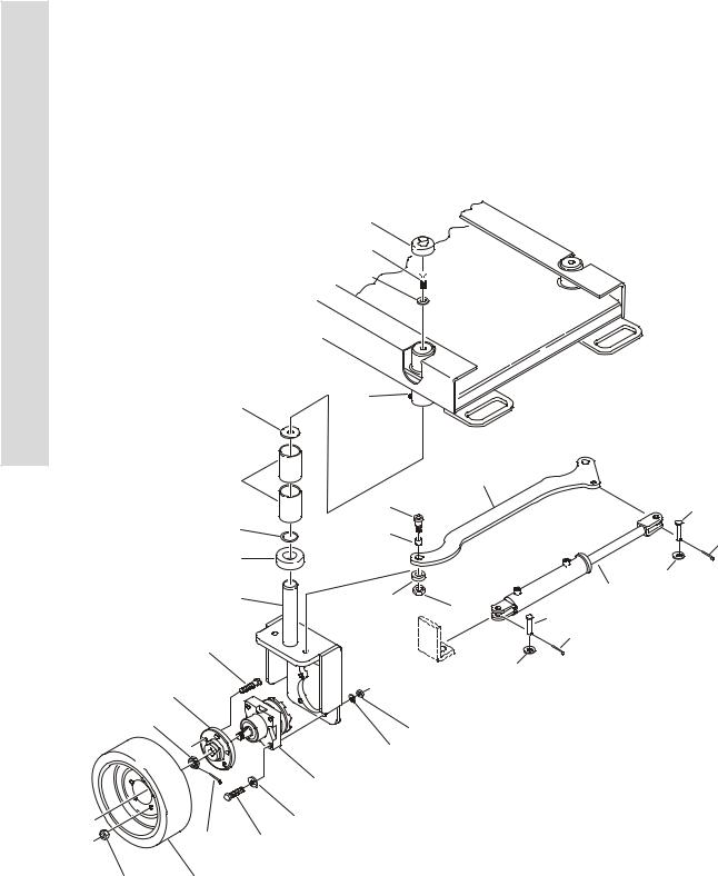
FIGURE 1-1. WHEEL DRIVE AND STEERING INSTALLATION - 1532E2 & 1932E2
2
9
1
4
19

|
8 |
|
|
|
|
22 |
11 |
|
|
|
|
7 |
1 |
|
17 |
|
12 |
|
|
|
|
||
|
3 |
|
|
|
13 |
16 |
6 |
|
|
|
15 |
|
|
|
14 |
||
23 |
|
|
|
|
21 |
|
|
|
|
10 |
|
18 |
5 |
25 |
|
20 |
|
|
12 |
||||
|
|
|
|
||
|
|
|
|
|
|
102A |
|
|
|
15 |
|
|
|
|
|
|
|
|
|
|
|
20 |
|
102
105
106
109
103
108
107 101
110
104 201
1-2 |
3120738 |

SECTION 1 FRAME
.
FIGURE 1-1. WHEEL DRIVE AND STEERING INSTALLATION - 1532E2 & 1932E2
FIG & ITEM # |
PART NUMBER |
DESCRIPTION |
QTY. |
REV. |
|
|
|
|
|
|
0258015 |
STEERING INSTALLATION |
Ref. |
J |
1 |
0100019 |
Loctite #271 |
A/R |
|
2 |
0100081 |
Loctite #454 |
A/R |
|
3 |
0630516 |
Bolt, Shoulder |
2 |
|
4 |
0641611 |
Bolt 3/8”-16NC x 1 3/8” |
2 |
|
5 |
0962208 |
Spacer, Bushing |
2 |
|
6 |
0962173 |
Bushing |
2 |
|
7 |
0962174 |
Bushing |
4 |
|
8 |
1120064 |
Cap, Grease Fitting (Prior to S/N 84437) |
2 |
|
9 |
1120515 |
Cap, Plastic |
2 |
|
10 |
|
Steer Cylinder Assembly (See Section 5 for Breakdown) |
1 |
|
|
Use 1684225 |
Prior to S/N 67287 (Was P/N 1683661) |
|
|
|
|
S/N 67287 to S/N 108168 (Was P/N 1683832) |
|
|
|
1684225 |
S/N 108168 to Present |
|
|
11 |
2160006 |
Fitting, Grease (Prior to S/N 84437) |
2 |
|
12 |
3430811 |
Pin, Clevis |
A/R |
|
13 |
3431014 |
Pin, Clevis (Prior to S/N 50027) |
1 |
|
14 |
3450404 |
Pin, Cotter 1/8” x 1” (Prior to S/N 50027) |
1 |
|
15 |
3450406 |
Pin, Cotter 1/8” x 1 1/2” |
A/R |
|
16 |
3790218 |
O-Ring (Prior to S/N 101149) |
2 |
|
17 |
3841378 |
Tie-Rod |
1 |
|
18 |
4130356 |
Spindle |
2 |
|
19 |
4711600 |
Flatwasher 3/8” Narrow |
2 |
|
20 |
4711800 |
Flatwasher 1/2” Narrow |
A/R |
|
21 |
4712000 |
Flatwasher 5/8” Narrow (Prior to S/N 50027) |
2 |
|
22 |
4740419 |
Thrustwasher |
2 |
|
23 |
|
Collar: |
2 |
|
|
Use 1440329 |
Prior to S/N 99064(1932E2)/ |
|
|
|
|
Prior to June 13, 2001(1532E2)(Was P/N 1440326) |
|
|
|
1440329 |
S/N 99064 to Present (1932E2)/ |
|
|
|
|
June 13, 2001to Present (1532E2) |
|
|
24 |
3020025 |
Grease (Not Shown) (Prior to S/N 108196) |
A/R |
|
25 |
3312002 |
Jam Nut (S/N 103651 to Present) |
2 |
|
|
|
WHEEL DRIVE INSTALLATION OPTIONS: |
Ref. |
|
|
0258171 |
(Prior to S/N 90870) |
Ref. |
F |
|
0271221 |
(S/N 90870 to Present) |
Ref. |
A |
101 |
|
Bolt Options: |
8 |
|
|
0641824 |
Bolt 1/2”-13NC x 3” (Prior to S/N 49303) |
|
|
|
0681822 |
Bolt 1/2”-13NC x 2 3/4” (S/N 49303 to Present) |
|
|
102 |
2780216 |
Hub Assembly |
2 |
|
102A |
7012613 |
Bolt, Wheel (5 Per Hub) |
10 |
|
103 |
|
Drive Motor Assembly Options: |
2 |
|
|
3160229 |
(Prior to S/N 90870) |
|
|
|
7018996 |
Key, Shaft |
1 |
|
|
7018997 |
Nut, Castle |
1 |
|
|
|
|
|
|
S E C T I O N
1
F
R A M E
3120738 |
1-3 |

S E C T I O N
1
F
R A M E
SECTION 1 FRAME
FIGURE 1-1. WHEEL DRIVE AND STEERING INSTALLATION - 1532E2 & 1932E2 (CONTINUED)
FIG & ITEM # |
PART NUMBER |
DESCRIPTION |
QTY. |
REV. |
|
|
|
|
|
103 (cont’d) |
7021312 |
Seal, Shaft Oil (Inner Seal) |
1 |
|
|
7021317 |
Seal, Dust (Outer Seal) |
1 |
|
|
3160269 |
(S/N 90870 to Present) (See Figure 1-2 for Breakdown) |
|
|
104 |
3300255 |
Nut, Wheel |
10 |
|
105 |
See Note |
Nut (Note: See Breakdown of Individual Motor) |
2 |
|
106 |
|
Hardware Options: |
8 |
|
|
3271805 |
Locknut 1/2”-13NC (Grade 8) (Prior to S/N 49303) |
|
|
|
3311801 |
Nut 1/2”-13NC (S/N 49303 to S/N 84080) |
|
|
|
3300450 |
Nut 1/2”-13NC (S/N 84080 to Present) |
|
|
107 |
3450406 |
Pin, Cotter 1/8” x 1 1/2” |
2 |
|
108 |
Use 4740453 |
Flatwasher 1/2” Narrow |
8 |
|
|
|
(Was P/N 4891800 Prior to S/N 90870) |
|
|
109 |
4761800 |
Lockwasher 1/2” (S/N 49303 to S/N 84080) |
8 |
|
110 |
0100019 |
Loctite #271 (Prior to S/N 84080) |
A/R |
|
|
|
TIRE AND WHEEL INSTALLATIONS |
Ref. |
|
|
0258167 |
Black Tire and Wheel Installation |
Ref. |
1 |
|
0258166 |
Gray Non-Marking Tire and Wheel Installation |
Ref. |
1 |
201 |
|
Tire Options: |
4 |
|
|
4860180 |
Standard Black |
A/R |
|
|
4860182 |
Non-Marking Gray |
A/R |
|
|
|
FRAME OPTIONS |
1 |
|
|
2360459 |
ANSI Machines (Prior to S/N 50363) |
|
|
|
2360482 |
ANSI Machines (S/N 50363 to Present) |
|
|
|
2360482 |
CSA Spec Machines |
|
|
|
|
|
|
|
1-4 |
3120738 |
|
|
SECTION 1 FRAME |
|
|
|
S |
|
FIGURE 1-1. WHEEL DRIVE AND STEERING INSTALLATION - 1532E2 & 1932E2 (CONTINUED) |
|
||||||
|
|
|
|
|
|
E |
|
FIG & ITEM # |
PART NUMBER |
DESCRIPTION |
QTY. |
REV. |
|
C |
|
|
|
|
|||||
|
|
|
|
|
|
T |
|
|
|
|
|
|
|
|
|
|
|
|
|
|
|
I |
|
|
|
|
|
|
|
O |
|
|
|
|
|
|
|
N |
|
|
|
|
|
|
|
1 |
|
|
|
|
|
|
|
F |
|
|
|
|
|
|
|
R |
|
|
|
|
|
|
|
A |
|
|
|
|
|
|
|
M |
|
|
|
|
|
|
|
E |
|
|
|
|
|
|
|
|
|
|
|
|
|
|
|
|
|
3120738 |
1-5 |

S E C T I O N
1
F
R A M E
SECTION 1 FRAME
FIGURE 1-2. DRIVE MOTOR ASSEMBLY - 1532E2 & 1932E2 (S/N 90870 TO PRESENT)
1-6 |
3120738 |

SECTION 1 FRAME
.
FIGURE 1-2. DRIVE MOTOR ASSEMBLY - 1532E2 & 1932E2 (S/N 90870 TO PRESENT)
FIG & ITEM # |
PART NUMBER |
DESCRIPTION |
QTY. |
REV. |
|
|
|
|
|
|
3160269 |
DRIVE MOTOR ASSEMBLY |
Ref. |
B |
1 |
7023451 |
Nut, Castle |
1 |
|
2 |
Not Used |
|
|
|
3 |
Use Item 100 |
Seal, Dust |
1 |
|
4 |
Not Serviceable |
Housing |
|
|
5 |
Use Item 100 |
O-Ring |
1 |
|
6 |
Use Item 100 |
Seal, Shaft |
1 |
|
7 |
7023452 |
Bearing, Race |
2 |
|
8 |
7023453 |
Bearing, Needle |
1 |
|
9 |
7023454 |
Bearing, Needle |
1 |
|
10 |
7023455 |
Key |
1 |
|
11 |
7023456 |
Shaft, Output |
1 |
|
12 |
Use Item 100 |
O-Ring |
1 |
|
13 |
7023457 |
Washer, Spring |
1 |
|
14 |
7023458 |
Plate, Pressure |
1 |
|
15 |
7023459 |
Disc, Valve |
1 |
|
16 |
7023460 |
Bearing, Needle |
1 |
|
17 |
7023461 |
Washer, Glacier |
1 |
|
18 |
7023462 |
Plate |
1 |
|
19 |
7023463 |
Shaft, Cardan |
1 |
|
20 |
Use Item 100 |
O-Ring |
2 |
|
21 |
7023464 |
Wheel, Gear Set |
1 |
|
22 |
7023465 |
Cover, End |
1 |
|
23 |
Not Serviceable |
I.D. Tag |
1 |
|
24 |
Use Item 100 |
Washer |
7 |
|
25 |
7023466 |
Screw |
7 |
|
26 |
Not Serviceable |
Plug |
2 |
|
|
|
KIT OPTIONS: |
Ref. |
|
100 |
7023450 |
Kit, Seal (Includes Items 3, 5-6, 12, 20, 24) |
1 |
|
|
|
|
|
|
S E C T I O N
1
F
R A M E
3120738 |
1-7 |
S E C T I O N
1
F
R A M E
SECTION 1 FRAME
FIGURE 1-3. BRAKE INSTALLATION - 1532E2 & 1932E2
|
7 |
109 15 |
108 |
110 |
4 |
3 |
|
2 102 |
|
113 |
111 |
112 |
|
101 |
|
103 |
|
201 |
|
8 |
|
9 |
|
11 |
|
13 |
|
14 |
12 |
16 |
10 |
|
|
5 |
|
|
6 |
|
|
1 |
|
1-8 |
3120738 |

SECTION 1 FRAME
FIGURE 1-3. BRAKE INSTALLATION - 1532E2 & 1932E2
FIG & ITEM # |
PART NUMBER |
DESCRIPTION |
QTY. |
REV. |
|
|
|
|
|
|
|
BRAKE INSTALLATION OPTIONS: |
Ref. |
|
|
0258168 |
1532E2 & 1932E2 Machines |
Ref. |
C |
1 |
|
Brake Cylinder Assembly Options |
1 |
|
|
|
(See Section 5 for Breakdown): |
|
|
|
Use 1683833 |
Prior to S/N 65498 (Was p/n 1683557) |
|
|
|
1683833 |
S/N 65498 to Present |
|
|
2 |
2780215 |
Hub Assembly (See Items 101-113 for Breakdown) |
2 |
|
3 |
3300255 |
Nut, Wheel |
10 |
|
4 |
3300423 |
Nut |
2 |
|
5 |
3430620 |
Pin |
2 |
|
6 |
3450403 |
Pin, Cotter 1/8” x 3/4” |
2 |
|
7 |
3450406 |
Pin, Cotter 1/8” x 1 1/2” |
2 |
|
8 |
3841332 |
Rod |
2 |
|
9 |
4160137 |
Spring, Compression |
2 |
|
10 |
4845037 |
Brake Cam Weldment |
2 |
|
11 |
0641407 |
Bolt 1/4”-20NC x 7/8” |
4 |
|
12 |
3311405 |
Locknut 1/4”-20NC |
4 |
|
13 |
3571067 |
Plate, Cover |
1 |
|
14 |
4711400 |
Flatwasher 1/4” Narrow |
8 |
|
15 |
4740468 |
Washer, Special |
2 |
|
16 |
4711600 |
Flatwasher 3/8” Narrow |
2 |
|
|
2780215 |
HUB ASSEMBLY |
Ref. |
B |
101 |
7010649 |
Seal |
1 |
|
102 |
Not Serviced |
Housing |
1 |
|
103 |
7019696 |
Stud, Wheel |
5 |
|
104 to 107 |
Not Used |
|
|
|
108 |
7010648 |
Cap, Dust |
1 |
|
109 |
7010646 |
Cone, Outer |
1 |
|
110 |
7010650 |
Cup, Outer |
1 |
|
111 |
7010651 |
Cup, Inner |
1 |
|
112 |
7010647 |
Cone, Inner |
1 |
|
113 |
1760165 |
Disc, Brake |
1 |
|
|
|
FRAME COMPONENTS |
Ref. |
|
201 |
4845628 |
Spindle |
2 |
|
|
|
TIRE AND WHEEL INSTALLATIONS (NOT SHOWN) |
Ref. |
|
|
0258167 |
Black Tire and Wheel Installation |
Ref. |
1 |
|
0258166 |
Gray Non-Marking Tire and Wheel Installation |
Ref. |
1 |
|
|
Tire Options: |
4 |
|
|
4860180 |
Standard Black |
A/R |
|
|
4860182 |
Non-Marking Gray |
A/R |
|
|
|
|
|
|
S E C T I O N
1
F
R A M E
3120738 |
1-9 |

S E C T I O N
1
F
R A M E
SECTION 1 FRAME
FIGURE 1-4. FRAME AND STEERING INSTALLATIONS - 2032E2/2632E2/2646E2/ 3246E2
300
7 200
19
17 12
22 |
2 |
|
|
19 |
3 |
|
|
11 |
|
101 |
|
|
|
5 |
|
112 |
|
|
|
|
111 |
|
3 |
|
|
20 |
|
|
|
|
||
|
|
|
|
|
|
|
|
|
16 |
13 |
4 |
|
|
|
|
||
|
|
7 |
|
6 |
10 |
|
|
|
|
||
|
|
|
|
21 |
|
15 |
|
|
|
14 |
8 |
|
|
|
103 |
||
|
|
|
|
|
|
|
|
110 |
23 |
18 |
|
|
|
109 |
1 |
|
|
|
24 |
|
|
||
|
|
|
|
||
|
|
|
|
|
|
|
9 |
|
5 |
|
|
|
108 |
|
|
|
|
|
|
|
11 |
|
|
|
|
|
|
|
|
|
|
|
10 |
|
|
1-10 |
3120738 |

SECTION 1 FRAME
.
FIGURE 1-4. FRAME AND STEERING INSTALLATIONS - 2032E2/2632E2/2646E2/3246E2
FIG & ITEM # |
PART NUMBER |
DESCRIPTION |
QTY. |
REV. |
|
|
|
|
|
|
|
STEERING INSTALLATION OPTIONS: |
Ref. |
|
|
0257627 |
2032E2/2632E2 Machines |
Ref. |
I |
|
0257670 |
2646E2/3246E2 Machines |
Ref. |
J |
1 |
0642022 |
Bolt 5/8”-11NC x 2 3/4” |
1 |
|
2 |
0642028 |
Bolt 5/8”-11NC x 3 1/2” |
1 |
|
3 |
0962097 |
Bushing, Excelite (Prior to S/N 49494) |
4 |
|
|
0440228 |
Bushing, Excelite (S/N 49494 to Present) |
4 |
|
4 |
1660237 |
Coupling, Tie-Rod End (Left Side) |
1 |
|
5 |
1660238 |
Coupling, Tie-Rod End (Right Side) |
2 |
|
6 |
|
Steer Cylinder Assembly (See Section 5 for Breakdown): |
1 |
|
|
Use 1684224 |
2032E2/2632E2 (Prior to S/N 67287) |
|
|
|
|
(Was P/N 1683552) |
|
|
|
1683831 |
2032E2/2632E2 (S/N 67287 to S/N 104717) |
|
|
|
1684224 |
2032E2/2632E2 (S/N 104717 to Present) |
|
|
|
Use 1684224 |
2646E2/3246E2 (Prior to S/N 66990) |
|
|
|
|
(Was P/N 1683552) |
|
|
|
1683831 |
2646E2/3246E2 (S/N 66990 to S/N 104717) |
|
|
|
1684224 |
2646E2/3246E2 (S/N 104717 to Present) |
|
|
7 |
2780223 |
Hub Assembly (See Items 101-112 for Breakdown) |
2 |
|
8 |
3300409 |
Nut, Jam (Left Hand Threads) |
1 |
|
9 |
3300423 |
Nut, Spindle |
2 |
|
10 |
3312005 |
Locknut 5/8”-20NC |
2 |
|
11 |
3322002 |
Nut, Jam 5/8”-18NF |
1 |
|
12 |
3422646 |
Pin, Spindle (Prior to S/N 57249) |
2 |
|
|
3422760 |
Pin, Spindle (S/N 57249 to Present) |
2 |
|
13 |
3430811 |
Pin, Clevis |
1 |
|
14 |
3450403 |
Pin, Cotter 1/8” x 3/4” |
1 |
|
15 |
3450406 |
Pin, Cotter 1/8” x 1 1/2” |
2 |
|
16 |
3450804 |
Pin, Cotter 1/4” x 1” |
2 |
|
17 |
3841344 |
Rod, Retaining |
2 |
|
18 |
|
Tie-Rod Options: |
1 |
|
|
Kit |
2032E2/2632E2 Machines |
|
|
|
Kit |
2646E2/3246E2 Machines |
|
|
19 |
4130346 |
Spindle Assembly |
2 |
|
20 |
4567246 |
Tube, Spacer |
2 |
|
21 |
4711800 |
Flatwasher 1/2” Narrow |
1 |
|
22 |
4740462 |
Thrustwasher, Bronze |
2 |
|
23 |
3300255 |
Nut, Wheel |
10 |
|
24 |
4740468 |
Flatwasher, Special |
2 |
|
|
|
--------------------------------------------------------------------------- |
|
|
|
|
Tie Rod Assembly Kit Options: |
1 |
|
|
2902137 |
2032E2 & 2632E2 (Includes Items Qty 1 of 4,5,8,11 & 18) |
|
|
|
2902138 |
2646E2 & 3246E2 (Includes Items Qty 1 of 4,5,8,11 & 18) |
|
|
|
|
|
|
|
S E C T I O N
1
F
R A M E
3120738 |
1-11 |

S E C T I O N
1
F
R A M E
SECTION 1 FRAME
FIGURE 1-4. FRAME AND STEERING INSTALLATIONS - 2032E2/2632E2/2646E2/3246E2 (CONTINUED)
FIG & ITEM # |
PART NUMBER |
DESCRIPTION |
QTY. |
REV. |
|
|
|
|
|
|
2780233 |
HUB ASSEMBLY |
Ref. |
A |
101 |
7010649 |
Seal, Oil |
1 |
|
102 |
Not Used |
|
|
|
103 |
7012613 |
Wheelbolt |
5 |
|
104 to 107 |
Not Used |
|
|
|
108 |
7003902 |
Cap |
1 |
|
109 |
7010646 |
Cone, Bearing (Outer) |
1 |
|
110 |
7003903 |
Cup, Bearing (Outer) |
1 |
|
111 |
7010651 |
Cup, Bearing (Inner) |
1 |
|
112 |
7010647 |
Cone, Bearing (Inner0 |
1 |
|
200 |
|
TIRE AND WHEEL INSTALLATION OPTIONS: |
Ref. |
|
|
0255682 |
Gray Non-Marking Tire Installation |
Ref. |
— |
|
0271541 |
Low Profile, Non-Marking Tire Installation (2632E2) |
Ref. |
|
|
0255679 |
Black Tire Installation |
Ref. |
— |
|
4520176 |
5x16 Gray Non-Marking (Standard) |
4 |
|
|
4520174 |
5x16 Black (Optional) |
4 |
|
|
4520257 |
5x16 Low Profile, Non-Marking (2632E2) |
4 |
|
300 |
|
FRAME WELDMENT OPTIONS: |
Ref. |
|
|
2360444 |
2032E2 Machines |
Ref. |
|
|
2360450 |
2646E2 Machines |
Ref. |
|
|
2360572 |
2632E2 Machines |
Ref. |
|
|
2360497 |
3246E2 Machines (Used with Rexroth Drive Motor) |
Ref. |
|
|
2360562 |
3246E2 Machines (Used With Parker Drive Motor) |
Ref. |
|
|
|
|
|
|
1-12 |
3120738 |
|
|
SECTION 1 FRAME |
|
|
|
S |
|
FIGURE 1-4. FRAME AND STEERING INSTALLATIONS - 2032E2/2632E2/2646E2/3246E2 |
|
|
|
||||
(CONTINUED) |
|
|
|
|
E |
|
|
FIG & ITEM # |
PART NUMBER |
DESCRIPTION |
QTY. |
REV. |
|
C |
|
|
|
|
|||||
|
|
|
|
|
|
T |
|
|
|
|
|
|
|
|
|
|
|
|
|
|
|
I |
|
|
|
|
|
|
|
O |
|
|
|
|
|
|
|
N |
|
|
|
|
|
|
|
1 |
|
|
|
|
|
|
|
F |
|
|
|
|
|
|
|
R |
|
|
|
|
|
|
|
A |
|
|
|
|
|
|
|
M |
|
|
|
|
|
|
|
E |
|
|
|
|
|
|
|
|
|
|
|
|
|
|
|
|
|
3120738 |
1-13 |

S E C T I O N
1
F
R A M E
SECTION 1 FRAME
FIGURE 1-5. WHEEL DRIVE AND BRAKE INSTALLATIONS - 2032E2/2632E2/ 2646E2/3246E2
200 |
|
|
|
|
2 |
|
|
|
|
|
|
|
|
|
|
|
2A |
|
|
|
|
|
2B |
|
|
|
|
|
2C |
|
|
|
|
|
7 |
|
4 |
8 |
3 |
6 |
|
|
|
|
|
3 |
|
|
|
|
|
|
1 |
|
|
|
103 |
|
9 |
104 |
|
|
106 |
|
|
|
|
|
|
|
|
|
|
|
|
|
5 |
105 |
|
|
|
|
|
|
107 |
|
|
|
103 |
102 |
|
|
|
106 |
|
|
|
|
|
||
|
101 |
|
|
|
|
|
|
|
102 |
107 |
105 |
|
|
|
|
104
1-14 |
3120738 |
SECTION 1 FRAME
.
FIGURE 1-5. WHEEL DRIVE AND BRAKE INSTALLATIONS - 2032E2/2632E2/2646E2/3246E2
FIG & ITEM # |
PART NUMBER |
DESCRIPTION |
QTY. |
REV. |
|
|
|
|
|
|
|
WHEEL DRIVE INSTALLATION OPTIONS: |
Ref. |
|
|
0257626 |
2032E2 Machines |
Ref. |
I |
|
0271228 |
2632E2 Machines |
Ref. |
A |
|
0257876 |
2646E2 Machines |
Ref. |
J |
|
0258898 |
3246E2 Machines (Prior to S/N 90855) |
Ref. |
G |
|
0271228 |
3246E2 Machines (S/N 90855 to Present) |
Ref. |
B |
1 |
|
Options: |
8 |
|
|
0681822 |
(Bolt 1/2”-13NC x 2 3/4” Grade 8) |
|
|
|
0681828 |
(Bolt 1/2”-13NC x 3 1/4” Grade 8) |
|
|
2 |
|
Hub Assembly Options: |
2 |
|
|
2780222 |
2032E2/2646E2 Machines |
|
|
|
|
2632E2/3246E2 Machines Options: |
|
|
|
2780238 |
Prior to S/N 90854 |
|
|
|
2780222 |
S/N 90855 to S/N 98951 |
|
|
|
See Note: |
S/N 98952 to S/N 99050 |
|
|
|
|
Note: For machines in this range contact JLG |
Ref. |
|
|
|
Industries Inc. |
|
|
|
2780238 |
S/N 99051 to S/N 102610 |
|
|
|
See Note: |
S/N 102611 to S/N 102640 |
|
|
|
|
Note: For machines in this range contact JLG |
Ref. |
|
|
|
Industries Inc. |
|
|
|
2780222 |
S/N 102641 to Present |
|
|
2A |
7012613 |
Stud, Wheel (5 per Hub) |
10 |
|
2B |
1760167 |
Disc, Brake |
2 |
|
2C |
2780216 |
Hub (Used w/2780222 Assembly) |
2 |
|
|
Not Available |
Hub (Used w/2780238 Assembly - Purchase Assem- |
2 |
|
|
|
bly) |
|
|
3 |
|
Drive Motor Assembly Options: |
A/R |
|
|
|
Note: Use Like Motors on Both Left & Right Sides |
Ref. |
|
|
|
2032E2 Motor Options: |
Ref. |
|
|
Use 2910312 |
2032E2 (Prior to S/N 86447) (Was p/n 3160230) |
2 |
|
|
3160258 |
2032E2 (S/N 86447 to S/N 90870) |
2 |
|
|
|
3160230 & 3160258 Replacement Parts: |
|
|
|
7018996 |
Key, Shaft |
1 |
|
|
7018997 |
Nut, Castle |
1 |
|
|
7021312 |
Seal, Shaft Oil (Inner Seal) |
1 |
|
|
7021317 |
Seal, Dust (Outer Seal) |
1 |
|
|
7023874 |
Cap, End |
1 |
|
|
3160263 |
2032E2 (S/N 90870 to Present) (See Figure 1-6 for |
2 |
|
|
|
Breakdown) |
|
|
|
|
2646E2 Motor Options: |
Ref. |
|
|
Use 2910313 |
2646E2 (Prior to S/N 87548) (Was p/n 3160226) |
2 |
|
|
3160259 |
2646E2 (S/N 87548 to 90870) |
2 |
|
|
|
3160226 & 3120259 Replacement Parts: |
|
|
|
7018996 |
Key, Shaft |
1 |
|
|
7018997 |
Nut, Castle |
1 |
|
|
7021312 |
Seal, Shaft Oil (Inner Seal) |
1 |
|
|
7021317 |
Seal, Dust (Outer Seal) |
1 |
|
|
|
|
|
|
S E C T I O N
1
F
R A M E
3120738 |
1-15 |

S E C T I O N
1
F
R A M E
SECTION 1 FRAME
FIGURE 1-5. WHEEL DRIVE AND BRAKE INSTALLATIONS - 2032E2/2632E2/2646E2/3246E2 (CONTINUED)
FIG & ITEM # |
PART NUMBER |
DESCRIPTION |
QTY. |
REV. |
|
|
|
|
|
3 (cont’d) |
7023874 |
Cap, End |
1 |
|
|
|
2632E2/3246E2 Motor Options: |
Ref. |
|
|
Use 2910342 |
Prior to S/N 62566 (was p/n 3160236 - Rexroth Motor) |
2 |
|
|
Use 2910342 |
S/N 62566 to S/N 90854 (was p/n 3160247 - Rexroth |
2 |
|
|
|
Motor) |
|
|
|
|
3160236 & 3160247 Replacement Parts: |
|
|
|
See Note |
Key, Shaft (was p/n 7022516) |
1 |
|
|
See Note |
Nut, Castle (was p/n 7022515) |
1 |
|
|
See Note |
Seal, Shaft Oil (Inner Seal) (was p/n 7022517) |
1 |
|
|
See Note |
Seal, Dust (Outer Seal) (was p/n 7022518) |
1 |
|
|
See Note |
Seal, Ring (was p/n 7022519) |
1 |
|
|
|
Note: Replacement Parts are no longer available for |
Ref. |
|
|
|
motor p/ns 3120236 & 3160247 - Use Kit p/n 2910342) |
|
|
|
|
Note: For replacement parts for 2910342 see Figure 1-6 |
Ref. |
|
|
3160265 |
S/N 90855 to S/N 98951 (Parker Hannofin Motor) (See |
2 |
|
|
|
Figure 1-6 for Breakdown) |
|
|
|
See Note: |
S/N 98952 to S/N 99050 |
2 |
|
|
|
Note: For machines in this range contact JLG |
Ref. |
|
|
|
Industries Inc. |
|
|
|
Use 3160265 |
S/N 99051 to S/N 102610 (Rexroth Motor) (was p/n |
2 |
|
|
|
3160247 - Rexroth Motor) |
|
|
|
See Note: |
S/N 102611 to S/N 102640 |
2 |
|
|
|
Note: For machines in this range contact JLG |
Ref. |
|
|
|
Industries Inc. |
|
|
|
3160265 |
S/N 102641 to Present (Parker Hannofin Motor) |
2 |
|
4 |
|
Hardware Options: |
8 |
|
|
3271805 |
Locknut 1/2”-13NC (Grade 8) (Prior to S/N 49303) |
|
|
|
3311801 |
Nut 1/2”-13NC (S/N 49303 to S/N 84080) |
|
|
|
3300450 |
Nut 1/2”-13NC (S/N 84080 to Present) |
|
|
5 |
|
Pin, Cotter Options: |
2 |
|
|
3450406 |
2032E2/2646E2 Machines (1/8” x 1 1/2”) |
|
|
|
3450508 |
3246E2 Machines (1/4” x 2”) (Prior to S/N 90855) |
|
|
|
3450406 |
3246E2 Machines (1/8” x 1 1/2”) (S/N 90855 to Present) |
|
|
6 |
|
Flatwasher Options: |
A/R |
|
|
4711800 |
2032E2/2646E2 Machines (Prior to S/N 87549) |
|
|
|
4740453 |
2032E2/2646E2 Machines (S/N 87549 to Present) |
|
|
|
4740453 |
3246E2 (S/N 102645 to Present) |
|
|
7 |
3300255 |
Nut, Wheel |
10 |
|
8 |
4761800 |
Flatwasher 1/2” (S/N 49303 to S/N 84080) |
8 |
|
9 |
0100019 |
Loctite #271 (Prior to S/N 84080) |
A/R |
|
|
|
BRAKE INSTALLATION OPTIONS: |
Ref. |
|
|
0257877 |
2032E2 / 2632E2 Machines |
Ref. |
D |
|
0257878 |
2646E2 / 3246E2 Machines |
Ref. |
D |
101 |
|
Brake Cylinder Assembly Options |
1 |
|
|
|
(See Section 5 for Breakdown): |
|
|
|
Use 1683833 |
Prior to S/N 65498 (Was p/n 1683557) |
|
|
|
1683833 |
S/N 65498 to Present |
|
|
102 |
3430620 |
Pin |
2 |
|
|
|
|
|
|
1-16 |
3120738 |

SECTION 1 FRAME
FIGURE 1-5. WHEEL DRIVE AND BRAKE INSTALLATIONS - 2032E2/2632E2/2646E2/3246E2 (CONTINUED)
FIG & ITEM # |
PART NUMBER |
DESCRIPTION |
QTY. |
REV. |
|
|
|
|
|
103 |
3450403 |
Pin, Cotter 1/8” x 3/4” |
2 |
|
104 |
|
Rod Options: |
2 |
|
|
3841332 |
2032E2 Machines |
|
|
|
3841371 |
2646E2/3246E3 Machines |
|
|
105 |
4160137 |
Spring, Compression |
2 |
|
106 |
4711600 |
Flatwasher 3/8” Narrow |
2 |
|
107 |
4845037 |
Brake Cam Weldment |
2 |
|
|
|
TIRE AND WHEEL INSTALLATION OPTIONS: |
Ref. |
|
|
0255682 |
Gray Non-Marking Tire Installation |
Ref. |
— |
|
0271541 |
Low Profile, Non-Marking Tire Installation (2632E2) |
Ref. |
|
|
0255679 |
Black Tire Installation |
Ref. |
— |
200 |
4520176 |
5x16 Gray Non-Marking (Standard) |
4 |
|
|
4520257 |
5x16 Low Profile, Non-Marking (2632E2) |
4 |
|
|
4520174 |
5x16 Black (Optional) |
4 |
|
|
|
|
|
|
S E C T I O N
1
F
R A M E
3120738 |
1-17 |

S E C T I O N
1
F
R A M E
SECTION 1 FRAME
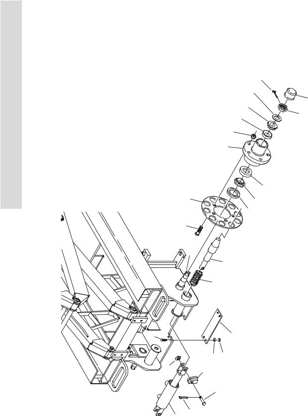
FIGURE 1-6. DRIVE MOTOR ASSEMBLY - (2032E2/2646E2 S/N 90870 TO PRESENT) (2632E2/3246E2 S/N 90855 TO PRESENT)
20
19

4 9 4 8 4 7 4 5 4 2 6 3 1 13


TORQUE TO |
|
50 FT. LBS. |
12 |
11 |
10 |
|
16 |
17 |
||
|
|
|
|
|
|
|
|
|
|
|
|
|
|
|
|
|
|
|
|
|
|
|
|
|
|
|
|
|
|
|
|
100 |
101 |
18
|
|
|
15 |
|
14 |
15 |
|||
|
|
|
|
|
|
|
|
|
|
|
|
|
|
|
|
|
|
|
|
|
|
|
|
|
|
|
|
|
|
|
|
|
|
|
|
|
|
|
|
|
|
|
|
|
|
|
|
|
|
|
|
|
|
|
|
|
|
|
|
|
|
|
|
|
|
|
|
|
|
|
|
|
|
|
|
|
|
|
|
|
|
|
|
|
|
|
|
|
|
|
|
|
|
|
|
|
|
|
|
|
|
|
|
|
|
|
|
|
|
|
|
|
|
|
|
|
|
|
|
|
|
|
|
|
|
|
|
|
|
1-18 |
3120738 |

SECTION 1 FRAME
.
FIGURE 1-6. DRIVE MOTOR ASSEMBLY - (2032E2/2646E2 S/N 90870 TO PRESENT) (2632E2/ 3246E2 S/N 90855 TO PRESENT)
FIG & ITEM # |
PART NUMBER |
|
DESCRIPTION |
QTY. |
REV. |
|
|
|
|
|
|
|
|
DRIVE MOTOR ASSEMBLIES (PARKER HANNIFIN) |
Ref. |
|
|
|
3160263 |
DRIVE MOTOR - 2032E2 |
Ref. |
B |
|
|
3160264 |
DRIVE MOTOR - 2646E2 |
Ref. |
B |
|
|
3160265 |
DRIVE MOTOR - 2632E2/3246E2 |
Ref. |
B |
|
|
2910342 |
DRIVE MOTOR - 3246E2 (This kit uses p/n 3160301 Motor) |
Ref. |
A |
|
1 |
|
Housing Options: |
1 |
|
|
|
7023307 |
3160263, 3160264 & 3160265 |
|
|
|
|
Not Serviced |
3160301 |
|
|
|
2 |
7023308 |
Bearing, Thrust |
1 |
|
|
3 |
|
Shaft Options: |
1 |
|
|
|
7023309 |
3160263 |
& 3160264 |
|
|
|
Not Serviced |
3160265 |
|
|
|
|
7026178 |
3160301 |
|
|
|
4 |
7023310 |
Ring, Seal |
|
5 |
|
5 |
7023311 |
Plate, Wear |
|
5 |
|
6 |
|
Drive Link Options: |
1 |
|
|
|
7023312 |
3160263 |
|
|
|
|
7023326 |
3160264 |
|
|
|
|
7023410 |
3160265 |
& 3160301 |
|
|
7 |
|
Assembly, Rotor Options: |
1 |
|
|
|
7023313 |
3160263 |
|
|
|
|
7023327 |
3160264 |
|
|
|
|
7023409 |
3160265 |
& 3160301 |
|
|
8 |
7023314 |
Manifold |
|
1 |
|
9 |
7023315 |
Assembly, Commutator |
1 |
|
|
10 |
7023318 |
Seal, Commutator |
1 |
|
|
11 |
|
Cover, End Options: |
1 |
|
|
|
7023316 |
3160263 |
|
|
|
|
7023328 |
3160264, 3160265 & 3160301 |
|
|
|
12 |
|
Bolt Options: |
7 |
|
|
|
7023317 |
3160263 |
|
|
|
|
7023329 |
3160264 |
& 3160265 |
|
|
|
Not Serviced |
3160301 |
|
|
|
13 |
See Note |
Seal (Note: Use Items 100 & 101) |
1 |
|
|
14 |
Not Available |
Identification Tag |
N/A |
|
|
15 |
7023320 |
Screw |
|
2 |
|
16 |
See Note |
Ring Back-Up (Note: Use Items 100 & 101) |
1 |
|
|
17 |
See Note |
Washer, Back-Up (Note: Use Items 100 & 101) |
1 |
|
|
18 |
See Note |
Seal, Shaft (Note: Use Items 100 & 101) |
1 |
|
|
19 |
|
Key Options: |
1 |
|
|
|
7023324 |
3160263, 3160264 & 3160265 |
|
|
|
|
7026179 |
3160301 |
|
|
|
20 |
|
Nut, Castle Options: |
1 |
|
|
|
7023325 |
3160263, 3160264 & 3160265 |
|
|
|
|
7026180 |
3160301 |
|
|
|
|
|
|
|
|
|
S E C T I O N
1
F
R A M E
3120738 |
1-19 |

S E C T I O N
1
F
R A M E
SECTION 1 FRAME
FIGURE 1-6. DRIVE MOTOR ASSEMBLY - (2032E2/2646E2 S/N 90870 TO PRESENT) (2632E2/ 3246E2 S/N 90855 TO PRESENT) (CONTINUED)
FIG & ITEM # |
PART NUMBER |
DESCRIPTION |
QTY. |
REV. |
|
|
|
|
|
21 |
|
Bearing, Inner Options (Not Shown): |
1 |
|
|
Not Required |
3160263 & 3160234 |
|
|
|
7023405 |
3160265 |
|
|
|
7026174 |
3160301 |
|
|
22 |
|
Washer, Thrust Options (Not Shown): |
A/R |
|
|
Not Required |
3160263 & 3160234 |
0 |
|
|
7023406 |
3160265 |
1 |
|
|
7026175 |
3160301 |
2 |
|
23 |
|
Bearing, Thrust Options (Not Shown): |
1 |
|
|
Not Required |
3160263 & 3160234 |
|
|
|
7023407 |
3160265 |
|
|
|
7026176 |
3160301 |
|
|
24 |
|
Bearing, Outer Options (Not Shown): |
1 |
|
|
Not Required |
3160263 & 3160234 |
|
|
|
7023408 |
3160265 |
|
|
|
7026177 |
3160301 |
|
|
|
|
KIT OPTIONS: |
Ref. |
|
|
|
Kit, Seal Options (Includes Items 4, 10, 13, 16, 17 & 18): |
|
|
100 |
7023412 |
3160263, 3160264 & 3160265 |
1 |
|
101 |
7026181 |
3160301 |
1 |
|
|
|
|
|
|
1-20 |
3120738 |

SECTION 1 FRAME
FIGURE 1-6. DRIVE MOTOR ASSEMBLY - (2032E2/2646E2 S/N 90870 TO PRESENT) (2632E2/ 3246E2 S/N 90855 TO PRESENT) (CONTINUED)
FIG & ITEM # |
PART NUMBER |
DESCRIPTION |
QTY. |
REV. |
|
|
|
|
|
|
|
|
|
|
S E C T I O N
1
F
R A M E
3120738 |
1-21 |

S E C T I O N
1
F
R A M E
SECTION 1 FRAME
FIGURE 1-7. FRAME MOUNTED COMPONENTS INSTALLATIONS
|
717 |
751 |
772 B |
NOTE: SEE SECTION 3 |
||
|
755 |
|
FOR ARM GUARD |
|||
|
|
|
LIMIT SWITCH |
|||
A |
|
|
770 |
|
|
|
766 |
|
771 |
|
|
|
|
|
|
|
|
|
||
304 |
|
|
|
|
|
766 |
|
|
|
|
|
765 |
|
|
|
768 |
769 |
767 |
|
|
LOCATION |
|
755 |
||||
MAY VARY |
|
|
|
|
|
|
|
|
|
603B |
F |
|
B |
|
|
|
603A |
|
A |
|
301 |
303 |
|
603 |
|
C |
|
|
|
|
|
|||
|
|
|
|
|
||
|
|
|
|
|
|
|
|
|
|
601 |
|
|
|
|
|
|
604 |
602 |
|
|
|
|
|
606 |
|
|
|
|
|
|
D |
|
|
|
4 |
|
E |
|
|
|
|
|
|
|
|
|
|
|
1 |
2 |
|
|
|
|
|
|
5 |
|
|
|
125 |
|
|
938 |
|
|
|
|
|
|
||
|
|
|
|
|
|
|
976838 |
|
|
|
|
|
|
|
876 |
127 |
|
|
|
|
|
501 |
|
|
|
|
|
|
959 |
|
|
|
|
|
|
130 |
|
|
|
|
|
|
|
|
859 |
|
|
|
|
|
|
118 |
|
975 |
|
201 |
|
|
|
|
|
875 |
|
202 |
|
|
128 |
|
974 |
920 |
|
|
|
|
|
||||
|
|
|
|
|
|
874 |
820 |
|
|
|
|
131 |
401 |
||
202A |
|
|
963 |
||||
|
|
151 |
|
402 |
863 |
||
|
|
|
|
147 |
|
|
963 |
|
|
|
203 |
D |
|
|
|
|
E |
114 |
|
|
|
863 |
|
|
|
|
872 |
973 |
|||
|
|
|
|
||||
|
|
|
|
972 |
873 F |
||
|
|
|
|
404 |
|
|
C |
|
|
|
|
|
|
|
|
|
|
|
|
403 |
|
405 |
|
|
|
|
|
409 |
|
||
|
|
|
|
|
|
||
1-22 |
3120738 |

SECTION 1 FRAME
.
FIGURE 1-7. FRAME MOUNTED COMPONENTS INSTALLATIONS
FIG & ITEM # |
PART NUMBER |
DESCRIPTION |
QTY. |
REV. |
|
|
|
|
|
|
|
LADDER INSTALLATIONS |
Ref. |
|
|
0257662 |
1532E2 |
Ref. |
B |
|
0257662 |
1932E2 |
Ref. |
B |
|
0257662 |
2032E2 without Optional Invertor |
Ref. |
B |
|
0258681 |
2032E2 with Optional Invertor |
Ref. |
A |
|
0257779 |
2632E2 |
Ref. |
A |
|
0257779 |
2646E2 |
Ref. |
A |
|
0258944 |
3246E2 |
Ref. |
A |
1 |
0100011 |
Loctite #242 |
A/R |
|
2 |
4711600 |
Flatwasher 3/8” Narrow |
4 |
|
3 |
Not Used |
|
|
|
4 |
|
Ladder Weldment Options: |
1 |
|
|
4845558 |
1532E2 |
|
|
|
4845558 |
1932E2 |
|
|
|
4845558 |
2032E2 without Optional Invertor |
|
|
|
4845837 |
2032E2 with Optional Invertor |
|
|
|
4845834 |
2632E2 |
|
|
|
4845834 |
2646E2 |
|
|
|
4845922 |
3246E2 |
|
|
5 |
0641605 |
Bolt 3/8”-16NC x 5/8” |
4 |
|
|
|
MANUAL DESCENT PUMP INSTALLATION |
Ref. |
|
|
|
(PRIOR TO S/N 69053 ONLY) |
|
|
|
0257666 |
2646E2 Machines Only |
Ref. |
M |
|
0258889 |
3246E2 Machines Only |
Ref. |
F |
101 to 113 |
Not Used |
|
|
|
114 |
0641528 |
Bolt 5/16”-18NC x 3 1/2” |
2 |
|
115 to 117 |
Not Used |
|
|
|
118 |
0721006 |
Screw, Machine #10-24NC x 3/4” |
2 |
|
119 to 124 |
Not Used |
|
|
|
125 |
1380136 |
Clip, Gripper |
2 |
|
126 |
Not Used |
|
|
|
127 |
2560122 |
Handle, Pump |
1 |
|
128 |
2560123 |
Handle, Grip |
|
|
129 |
Not Used |
|
|
|
130 |
3311005 |
Locknut #10-24NC |
4 |
|
131 |
3311505 |
Locknut 5/16”-18NC |
2 |
|
132 to 146 |
Not Used |
|
|
|
147 |
4640859 |
Pump Assembly - Manual Descent |
1 |
|
|
|
(See 201-203 for Breakdown) |
|
|
148 to 149 |
Not Used |
|
|
|
150 |
0100001 |
Adhesive, Weatherstrip (Not Shown) |
A/R |
|
151 |
4751500 |
Flatwasher 5/16” |
2 |
|
|
|
|
|
|
S E C T I O N
1
F
R A M E
3120738 |
1-23 |

S E C T I O N
1
F
R A M E
SECTION 1 FRAME
FIGURE 1-7. FRAME MOUNTED COMPONENTS INSTALLATIONS (CONTINUED)
FIG & ITEM # |
PART NUMBER |
DESCRIPTION |
QTY. |
REV. |
|
|
|
|
|
|
4640859 |
PUMP ASSEMBLY - MANUAL DESCENT |
Ref. |
|
|
|
(2646E2 & 3246E2 MACHINES ONLY) |
|
|
201 |
7012952 |
Cartridge, Pump |
1 |
|
|
2900708 |
Seal Kit - 7012952 Cartridge |
1 |
|
202 |
7012954 |
Cartridge, Needle Valve |
1 |
|
|
7012953 |
Seal Kit - 7012954 Cartridge |
1 |
|
202A |
7012961 |
Knob |
1 |
|
203 |
7012955 |
Cartridge, Check |
1 |
|
|
7012540 |
Seal Kit - 7012955 Cartridge |
1 |
|
|
|
TILT INDICATOR INSTALLATIONS |
Ref. |
|
|
|
All Specs except Japanese Spec: |
Ref. |
|
|
0270066 |
1532E2 (1.5°) |
Ref. |
B |
|
0257969 |
1932E2/2032E2/2646E2 Prior to S/N 71686 (5°) |
Ref. |
C |
|
0270066 |
1932E2/2032E2 S/N 71686 to Present (1.5°) |
Ref. |
B |
|
0257799 |
2632E2 (2°) |
Ref. |
A |
|
0259410 |
2632E2 with Prop Controls (2°) |
Ref. |
A |
|
0257799 |
2646E2 S/N 71686 to Present (2°) |
Ref. |
A |
|
0257969 |
3246E2 with Std Controls Prior to S/N 71686 (5°) |
Ref. |
C |
|
0257799 |
3246E2 with Std Controls S/N71686 to Present (2°) |
Ref. |
D |
|
0259410 |
3246E2 with Prop Controls (2°) |
Ref. |
A |
|
|
Japanese Spec: |
Ref. |
|
|
0257969 |
1532E2 (5°) |
Ref. |
A |
|
0257969 |
1932E2/2032E2/2646E2 Prior to S/N 71686 (5°) |
Ref. |
C |
|
0270066 |
1932E2/2032E2 S/N 71686 to S/N 79269 (1.5°) |
Ref. |
B |
|
0257969 |
1932E2/2032E2 S/N 79269 to Present (5°) |
Ref. |
C |
|
0257969 |
2632E2 (°5) |
Ref. |
C |
|
0257799 |
2646E2 S/N 71686 to S/N 79269 (2°) |
Ref. |
A |
|
0257969 |
2646E2 S/N 71686 to Present (5°) |
Ref. |
A |
|
0257969 |
3246E2 with Std Controls Prior to S/N 71686 (5°) |
Ref. |
C |
|
0257799 |
3246E2 with Std Controls S/N 71686 to S/N 79269 (2°) |
Ref. |
D |
|
0257969 |
3246E2 with Std Controls S/N 71686 to Present (5°) |
Ref. |
D |
|
0259410 |
3246E2 with Prop Controls Prior to S/N 79269 (2°) |
Ref. |
A |
|
0257969 |
3246E2 with Prop Controls S/N 71686 to Present (5°) |
Ref. |
D |
301 |
0641405 |
Bolt 1/4”-20NC x 5/8” |
2 |
|
302 |
Not Used |
|
|
|
303 |
3311405 |
Locknut 1/4”-20NC |
2 |
|
304 |
|
Indicator, Tilt Options: |
1 |
|
|
4360487 |
1.5° |
|
|
|
4360349 |
2° (Standard Controls Machines) |
|
|
|
4360435 |
2° (Prop Controls Machines) |
|
|
|
4360348 |
5° |
|
|
|
|
|
|
|
1-24 |
3120738 |
Loading...