


 Loading...
Illustrated Parts Manual
Model 26MRT
P/N
3120893
October 17, 2013
REVISION LOG
February 4, 2000 - Original Issue Of Manual (Was part of complete Manual #3120844) (Edited to 0010520 Revision 37) October 30, 2000 - Revised (Edited to 0010520 Revision 37)
February 25, 2004 - Revised
September 15, 2007 - Revised
June 24, 2011 - Revised
October 17, 2013 - Revised
3120893 |
A |
REVISION LOG
B |
3120893 |
TABLE OF CONTENTS
FIGURE NO. |
TITLE |
PAGE NO. |
SECTION 1 - FRAME . . . . . . . . . . |
. . . . . . . . . . . . . . . . . . . . . . . . . . . . . . . . . . . . . . . . . |
. . .1-1 |
1-1 FRAME AND STEERING INSTALLATION . . . . . . . . . . . . . . . . . . . . . . . . . . . . . . . . . . . .1-2 1-2 REAR DRIVE INSTALLATION. . . . . . . . . . . . . . . . . . . . . . . . . . . . . . . . . . . . . . . . . . . . . .1-4 1-3 DRIVE MOTOR ASSEMBLY. . . . . . . . . . . . . . . . . . . . . . . . . . . . . . . . . . . . . . . . . . . . . . .1-6 1-4 DRIVE BRAKE ASSEMBLY . . . . . . . . . . . . . . . . . . . . . . . . . . . . . . . . . . . . . . . . . . . . . . .1-8 1-5 DRIVE AXLE ASSEMBLY . . . . . . . . . . . . . . . . . . . . . . . . . . . . . . . . . . . . . . . . . . . . . . . . .1-10 1-6 FRAME MOUNTED COMPONENTS INSTALLATION . . . . . . . . . . . . . . . . . . . . . . . . . . .1-12
SECTION 2 - GROUND COMPONENTS . . . . . . . . . . . . . . . . . . . . . . . . . . . . . . . . . . . . . . .2-1
2-1 CONTROL VALVES & TANKS INSTALLATION . . . . . . . . . . . . . . . . . . . . . . . . . . . . . . . .2-2 2-2 CONTROL VALVES ASSEMBLY . . . . . . . . . . . . . . . . . . . . . . . . . . . . . . . . . . . . . . . . . . .2-6 2-3 VANGUARD GAS ENGINE INSTALLATION (PRIOR TO S/N 48113) . . . . . . . . . . . . . . .2-8 2-4 VANGUARD GAS ENGINE INSTALLATION (S/N 48113 TO PRESENT). . . . . . . . . . . . .2-14 2-5 DUAL FUEL INSTALLATION (VANGUARD MACHINES ONLY) . . . . . . . . . . . . . . . . . . .2-18 2-6 YANMAR DIESEL ENGINE INSTALLATION . . . . . . . . . . . . . . . . . . . . . . . . . . . . . . . . . .2-22 2-7 PISTON PUMP ASSEMBLY . . . . . . . . . . . . . . . . . . . . . . . . . . . . . . . . . . . . . . . . . . . . . .2-26 2-8 GEAR PUMP ASSEMBLY (YANMAR ENGINE) . . . . . . . . . . . . . . . . . . . . . . . . . . . . . . . .2-28 2-9 GROUND CONTROLS INSTALLATION . . . . . . . . . . . . . . . . . . . . . . . . . . . . . . . . . . . . . .2-30 2-10 HOOD INSTALLATIONS . . . . . . . . . . . . . . . . . . . . . . . . . . . . . . . . . . . . . . . . . . . . . . . . .2-34
SECTION 3 - SCISSOR ARMS. . . . . . . . . . . . . . . . . . . . . . . . . . . . . . . . . . . . . . . . . . . . . . .3-1
3-1 SCISSOR ARMS INSTALLATION . . . . . . . . . . . . . . . . . . . . . . . . . . . . . . . . . . . . . . . . . .3-2 3-2 ARM GUARDS INSTALLATION (PRIOR TO S/N 54142) . . . . . . . . . . . . . . . . . . . . . . . .3-6 3-3 ARM GUARDS INSTALLATION (S/N 54142 TO PRESENT) . . . . . . . . . . . . . . . . . . . . . .3-10
SECTION 4 - PLATFORM. . . . . . . . . . . . . . . . . . . . . . . . . . . . . . . . . . . . . . . . . . . . . . . . . . .4-1
4-1 PLATFORM COMPONENTS INSTALLATION - MANUALLY OPERATED
EXTENSION . . . . . . . . . . . . . . . . . . . . . . . . . . . . . . . . . . . . . . . . . . . . . . . . . . . . . . . .4-2 4-2 STANDARD HANDRAILS & EXTENSION INSTALLATION (MANUALLY
OPERATED PLATFORM). . . . . . . . . . . . . . . . . . . . . . . . . . . . . . . . . . . . . . . . . . . . . .4-6 4-3 PLATFORM CONSOLE BOX ASSEMBLY . . . . . . . . . . . . . . . . . . . . . . . . . . . . . . . . . . . .4-10 4-4 CONTROLLER ASSEMBLY (PRIOR TO S/N 58990) . . . . . . . . . . . . . . . . . . . . . . . . . . . .4-14 4-5 CONTROLLER ASSEMBLY (S/N 58990 TO PRESENT) . . . . . . . . . . . . . . . . . . . . . . . . .4-16
SECTION 5 - CYLINDERS . . . . . . . . . . . . . . . . . . . . . . . . . . . . . . . . . . . . . . . . . . . . . . . . . .5-1
5-1 LIFT CYLINDER COMPONENTS ASSEMBLY (PRIOR TO S/N 26916) . . . . . . . . . . . . .5-2 5-2 LIFT CYLINDER COMPONENTS ASSEMBLY (S/N 26916 TO PRESENT) . . . . . . . . . .5-6 5-3 STEER CYLINDER ASSEMBLY . . . . . . . . . . . . . . . . . . . . . . . . . . . . . . . . . . . . . . . . . . . .5-10
SECTION 6 - HYDRAULIC . . . . . . . . . . . . . . . . . . . . . . . . . . . . . . . . . . . . . . . . . . . . . . . . . .6-1
6-1 HYDRAULIC DIAGRAM - STANDARD . . . . . . . . . . . . . . . . . . . . . . . . . . . . . . . . . . . . . .6-2 6-2 HYDRAULIC DIAGRAM LIST . . . . . . . . . . . . . . . . . . . . . . . . . . . . . . . . . . . . . . . . . . . . . .6-6
SECTION 7 - ELECTRICAL . . . . . . . . . . . . . . . . . . . . . . . . . . . . . . . . . . . . . . . . . . . . . . . . .7-1
7-1 ELECTRICAL DIAGRAM LIST . . . . . . . . . . . . . . . . . . . . . . . . . . . . . . . . . . . . . . . . . . . . .7-2 7-2 ELECTRICAL SCHEMATIC - VANGUARD . . . . . . . . . . . . . . . . . . . . . . . . . . . . . . . . . . . .7-4 7-3 ELECTRICAL SCHEMATIC - YANMAR . . . . . . . . . . . . . . . . . . . . . . . . . . . . . . . . . . . . . .7-6 7-4 HARNESS AND CABLE ASSEMBLIES. . . . . . . . . . . . . . . . . . . . . . . . . . . . . . . . . . . . . .7-8
3120893 |
i |
TABLE OF CONTENTS
FIGURE NO. |
TITLE |
PAGE NO. |
SECTION 8 - DECALS . . . . . . . . . . . . . . . . . . . . . . . . . . . . . . . . . . . . . . . . . . . . . . . . . . |
. . . 8-1 |
|
8-1 |
DECALS INSTALLATIONS . . . . . . . . . . . . . . . . . . . . . . . . . . . . . . . . . . . . . . . . . |
. . . . 8-2 |
SECTION 9 - RECOMMENDED SERVICE PARTS STOCK . . . . . . . . . . . . . . . . . . . . . . . . 9-1 SECTION 10 - SPECIAL OPTIONS . . . . . . . . . . . . . . . . . . . . . . . . . . . . . . . . . . . . . . . . . . . 10-1
ii |
3120893 |
|
SECTION 1 FRAME |
|
|
|
|
|
|
|
S |
|
|
|
|
|
|
|
|
|
|
|
|
E |
|
|
TABLE OF CONTENTS |
|
|
|
|
|
|
|
|
C |
|
FIGURE |
DESCRIPTION |
PAGE |
|
T |
|
|
|
|
|||
|
|
|
|
I |
|
1-1 Frame And Steering Installation |
1-2 |
|
|
||
|
|
|
|||
1-2 |
Rear Drive Installation . . . . . . . . . . . . . . . . . . . . . . . . . . . . . . . . . . . . . . . . . . . . . . . . . . . . . |
. 1-4. . |
|
O |
|
1-3 |
Drive Motor Assembly . . . . . . . . . . . . . . . . . . . . . . . . . . . . . . . . . . . . . . . . . . . . . . . . . . . . . |
. 1-6. . |
|
|
|
1-4 |
Drive Brake Assembly . . . . . . . . . . . . . . . . . . . . . . . . . . . . . . . . . . . . . . . . . . . . . . . . . . . . . |
. 1-8. . |
|
N |
|
1-5 |
Drive Axle Assembly . . . . . . . . . . . . . . . . . . . . . . . . . . . . . . . . . . . . . . . . . . . . . . . . . . . . . . . |
. 1-10. . |
|
|
|
1-6 Frame Mounted Components Installation . . . . . . . . . . . . . . . . . . . . . . . . . . . . . . . . . . . . . . |
. 1-12. . |
|
1 |
|
|
|
|
|
|
|
|
|
|
|
|
F |
|
|
|
|
|
R |
|
|
|
|
|
A |
|
|
|
|
|
M |
|
|
|
|
|
E |
|
|
|
|
|
|
|
|
|
|
|
|
|
3120893 |
1-1 |

S E C T I O N
1
F
R A M E
SECTION 1 FRAME
FIGURE 1-1. FRAME AND STEERING INSTALLATION
13 |
15 |
14 |
|
12 |
17 |
|
11 |
|
10
9
3 |
18 |
16 201 |
2 |
16 |
201 |
18 |
6 |
4 |
5 |
|
|
6 |
|
|
|
|
|
102 |
|
|
|
|
7 |
8 |
105 |
|
|
|
|
|
||
|
|
|
|
|
|
101 |
|
|
||
|
|
|
|
107 |
1 |
|
|
|
103 |
104 |
|
|
|
|
|
|
19 |
|
|
|
204 |
|
|
|
|
|
|
|
20 |
203 |
|
|
|
|
|
|
|
|
|
|
205 |
|
106 |
1-2 |
3120893 |

SECTION 1 FRAME
.
FIGURE 1-1. FRAME AND STEERING INSTALLATION
FIG & ITEM # |
PART NUMBER |
DESCRIPTION |
QTY. |
REV. |
|
|
|
|
|
|
2360420 |
FRAME WELDMENT |
1 |
|
|
0255118 |
STEERING & SPINDLES INSTALLATION |
Ref. |
8 |
1 |
2780221 |
Hub Assembly (Includes Items 101-107) |
2 |
|
2 |
4130286 |
Spindle Weldment (Includes Items 201-205) |
2 |
|
3 |
3422610 |
Kingpin |
2 |
|
4 |
3450810 |
Pin, Cotter 1/4” x 2 1/2” |
2 |
|
5 |
3313003 |
Nut, Slotted 1 1/4”-7NC |
2 |
|
6 |
0440162 |
Washer, Thrust |
2 |
|
7 |
0642016 |
Bolt 5/8”-16NC x 2” |
2 |
|
8 |
3312005 |
Locknut 5/8”-16NC |
2 |
|
9 |
3841146 |
Rod-End |
2 |
|
10 |
3322002 |
Nut, Jam 5/8”-16NC |
2 |
|
11 |
|
Steer Cylinder Assembly (See Section 5 For Breakdown) |
1 |
|
|
|
Options: |
|
|
|
1683239 |
Prior to S/N 46538 |
|
|
|
1683697 |
S/N 46538 to Present |
|
|
12 |
3340644 |
Pad, Wear |
1 |
|
13 |
0641508 |
Bolt 5/16”-18NC x 1” |
1 |
|
14 |
3311505 |
Locknut 5/16”-18NC |
1 |
|
15 |
4751500 |
Flatwasher 5/16” |
2 |
|
16 |
3020022 |
Grease |
A/R |
|
17 |
4070809 |
Shim |
A/R |
|
18 |
3780182 |
O-Ring |
4 |
|
19 |
|
Nut, Wheel Options: |
10 |
|
|
3300255 |
Prior to S/N 32539 |
|
|
|
3300407 |
S/N 32539 to Present |
|
|
20 |
4752200 |
Flatwasher 3/4” |
2 |
|
|
2780221 |
HUB ASSEMBLY |
Ref. |
|
101 |
7012519 |
Cup, Bearing - Inner (1 Per Hub) |
2 |
|
102 |
7012520 |
Cone, Bearing - Inner (1 Per Hub) |
2 |
|
103 |
7012521 |
Cup, Bearing - Outer (1 Per Hub) |
2 |
|
104 |
7012522 |
Cone, Bearing - Outer (1 Per Hub) |
2 |
|
105 |
7012523 |
Seal (1 Per Hub) |
2 |
|
106 |
7012524 |
Cap, Dust (1 Per Hub) |
2 |
|
107 |
7016360 |
Stud, Wheel (5 Per Hub) |
10 |
|
|
4130286 |
SPINDLE WELDMENT |
Ref. |
|
201 |
0961621 |
Bushing, Bronze (2 Per Spindle) |
4 |
|
202 |
Not Used |
|
|
|
203 |
7012542 |
Washer (1 Per Spindle) |
2 |
|
204 |
7012541 |
Nut, Slotted (1 Per Spindle) |
2 |
|
205 |
7012543 |
Pin, Cotter (1 Per Spindle) |
2 |
|
|
|
|
|
|
S E C T I O N
1
F
R A M E
3120893 |
1-3 |

|
SECTION 1 FRAME |
S |
FIGURE 1-2. REAR DRIVE INSTALLATION |
E |
|
C |
|
T |
|
I |
|
O |
|
N |
|
1
F
R
A
M
E
1-4 |
3120893 |
SECTION 1 FRAME
FIGURE 1-2. REAR DRIVE INSTALLATION
FIG & ITEM # |
PART NUMBER |
DESCRIPTION |
QTY. |
REV. |
|
|
|
|
|
|
0256775 |
REAR DRIVE AXLE INSTALLATION |
Ref. |
3 |
1 |
3160215 |
Drive Motor Assembly (See Figure 1-3 for Breakdown) |
1 |
|
2 |
0920107 |
Drive Brake Assembly (See Figure 1-4 for Breakdown) |
2 |
|
3 |
1360265 |
Drive Shaft Assembly |
1 |
|
3A |
7011120 |
Journal & Bearing Kit |
2 |
|
3B |
7011121 |
U-Bolt Assembly |
1 |
|
3C |
7011122 |
Yoke |
2 |
|
3D |
7011123 |
Yoke, Splined |
1 |
|
4 |
0280150 |
Drive Axle Assembly (See Figure 1-5 for Breakdown) |
1 |
|
5 |
0630488 |
U-Bolt |
4 |
|
6 |
4711800 |
Flatwasher 1/2” (Narrow) |
14 |
|
7 |
3321805 |
Locknut 1/2”-20NF |
8 |
|
8 |
0641844 |
Bolt 1/2”-13NC x 5 1/2” |
4 |
|
9 |
3311805 |
Locknut 1/2”-13NC |
4 |
|
10 |
3931824 |
Capscrew, Socket Head 1/2”-13NC x 1 1/2” |
2 |
|
11 |
|
Nut, Wheel 1/2”-20NF Options: |
10 |
|
|
3300255 |
Prior to S/N 32539 |
|
|
|
3300407 |
S/N 32539 to S/N 46538 |
|
|
12 |
0100011 |
Loctite #242 (Not Shown) |
A/R |
|
13 |
3020008 |
Lube, Gear (Not Shown) |
A/R |
|
14 |
0920108 |
Drum, Brake |
2 |
|
15 |
0080227 |
Adapter, Motor |
1 |
|
16 |
1360269 |
Clevis (Right Side) |
1 |
|
17 |
1360270 |
Clevis (Left Side) |
1 |
|
18 |
0060036 |
Actuator |
2 |
|
19 |
0641710 |
Bolt 7/16”-14NC x 1 1/4” |
4 |
|
20 |
4060926 |
Shield, Actuator |
2 |
|
21 |
3311705 |
Locknut 7/16”-14NC |
4 |
|
22 |
4070957 |
Shim, Axle |
2 |
|
23 |
1120064 |
Cap, Grease Fitting (Not Shown) |
4 |
|
|
0256794 |
TIRE AND WHEEL INSTALLATION |
Ref. |
2 |
101 |
4520188 |
Tire and Wheel Assembly - 27 x 10.50 NHS -6 Ply |
2 |
|
|
|
(Right Side) (Foam Filled) |
|
|
|
4520189 |
Tire and Wheel Assembly - 27 x 10.50 NHS -6 Ply |
2 |
|
|
|
(Left Side) (Foam Filled) |
|
|
|
|
Note: Assemblies may require ballast/foam filling |
Ref. |
|
|
|
to manufacturer’s specifications prior to installing |
|
|
|
|
on a machine. Refer to Operation & Safety or Ser- |
|
|
|
|
vice & Maintenance Manuals. Purchase individual |
|
|
|
|
tire and/or rim only if able to foam fill tire & wheel |
|
|
|
|
assembly, otherwise, purchase complete assem- |
|
|
|
|
bly. |
|
|
|
7020112 |
Tire, 27 x 10.50 x 15 |
A/R |
|
|
7020113 |
Wheel, 15 x 8 |
A/R |
|
102 |
3300255 |
Nut, Wheel 1/2”-20NF (S/N 46538 to Present) |
20 |
|
|
|
|
|
|
S E C T I O N
1
F
R A M E
3120893 |
1-5 |
|
SECTION 1 FRAME |
S |
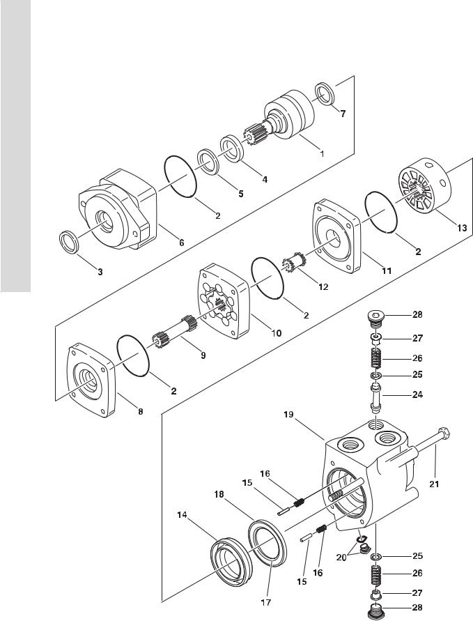
FIGURE 1-3. DRIVE MOTOR ASSEMBLY |
E |
|
C |
|
T |
|
I |
|
O |
|
N |
|
1
F
R
A
M
E
1-6 |
3120893 |

SECTION 1 FRAME
.
FIGURE 1-3. DRIVE MOTOR ASSEMBLY
FIG & ITEM # |
PART NUMBER |
DESCRIPTION |
QTY. |
REV. |
|
|
|
|
|
|
3160215 |
DRIVE MOTOR ASSEMBLY |
Ref. |
|
1 |
7014901 |
Shaft Sub-Assembly |
1 |
|
2 |
7014912 |
Seal |
4 |
|
3 |
Kit |
Seal, Exclusion |
1 |
|
4 |
Kit |
Seal, Shaft |
1 |
|
5 |
7009919 |
Ring, Back-Up |
1 |
|
6 |
Not Serviced |
Housing, Bearing |
1 |
|
7 |
Kit |
Seal, Shaft Face |
1 |
|
8 |
7009982 |
Plate, Wear |
1 |
|
9 |
7009936 |
Drive |
1 |
|
10 |
7009937 |
Geroler Assembly |
1 |
|
11 |
7009983 |
Plate, Valve |
1 |
|
12 |
7009905 |
Drive, Valve |
1 |
|
13 |
7009927 |
Valve |
1 |
|
14 |
7009909 |
Ring, Balance |
1 |
|
15 |
7009912 |
Pin, Balance Ring |
2 |
|
16 |
7009913 |
Spring, Compression |
2 |
|
17 |
7009910 |
Seal, Inner Face |
1 |
|
18 |
7009928 |
Seal, Outer Face |
1 |
|
19 |
7014913 |
Housing, Valve |
1 |
|
20 |
7002157 |
Plug/O-Ring Assembly |
1 |
|
|
7002158 |
O-Ring |
1 |
|
21 |
Not Serviced |
Bolt |
4 |
|
22 to 23 |
Not Used |
|
|
|
24 |
7014914 |
Piston, Shuttle |
1 |
|
25 |
7014915 |
Poppet |
2 |
|
26 |
7014916 |
Spring |
2 |
|
27 |
7014917 |
Sleeve |
2 |
|
28 |
7009940 |
Plug/O-Ring Assembly |
2 |
|
|
7009941 |
O-Ring |
2 |
|
|
2900699 |
Seal Kit (Includes Items 3, 4 & 7) |
1 |
|
|
|
|
|
|
S E C T I O N
1
F
R A M E
3120893 |
1-7 |

|
SECTION 1 FRAME |
S |
FIGURE 1-4. DRIVE BRAKE ASSEMBLY |
E |
|
C |
|
T |
|
I |
|
O |
|
N |
|
1 |
|
F |
|
R |
|
A |
|
M |
|
E |
|
|
|
1-8 |
3120893 |

SECTION 1 FRAME
.
FIGURE 1-4. DRIVE BRAKE ASSEMBLY
FIG & ITEM # |
PART NUMBER |
DESCRIPTION |
QTY. |
REV. |
|
|
|
|
|
|
0920107 |
DRIVE BRAKE ASSEMBLY |
Ref. |
|
|
|
Note: Drum not included in Brake Assembly but shown |
Ref. |
|
|
|
here for reference. |
|
|
1 |
7016631 |
O-Ring |
1 |
|
2 |
7016632 |
Cam |
1 |
|
3 |
7016633 |
Shoe Assembly - Single (Requires 2 per side/4 per |
A/R |
|
|
|
machine) |
|
|
4 |
7016634 |
Plate, Backing |
1 |
|
5 |
7016635 |
Spring, Return |
2 |
|
6 |
7016636 |
Lever |
1 |
|
7 |
7016637 |
Rollpin |
1 |
|
8 |
0920108 |
Drum (was p/n 0920218) |
1 |
|
|
|
|
|
|
S E C T I O N
1
F
R A M E
3120893 |
1-9 |

S E C T I O N
1
F
R A M E
SECTION 1 FRAME
FIGURE 1-5. DRIVE AXLE ASSEMBLY
12
11 |
10 |
9 |
|
8 |
|
7 |
5 |
|
6 |
4

 3
3
1
|
|
|
2 |
32 |
30 |
|
|
33 |
|
|
|
34 |
|
|
|
35 |
23 |
39 |
15 |
36 |
|
21 |
|
|
20 |
|
14 |
31 |
39 |
|
|
37 |
|
|
|
|
18 |
17 |
16 |
38 |
|
19 |
|
1-10 |
3120893 |

SECTION 1 FRAME
.
FIGURE 1-5. DRIVE AXLE ASSEMBLY
FIG & ITEM # |
PART NUMBER |
DESCRIPTION |
QTY. |
REV. |
|
|
|
|
|
|
0280150 |
DRIVE AXLE ASSEMBLY |
Ref. |
|
1 |
7019033 |
Housing |
1 |
|
2 |
7019000 |
Drive Gear & Pinion |
1 |
|
3 |
7019001 |
Bearing, Inner Pinion |
1 |
|
4 |
Kit |
Shim, Drive Pinion Adjusting |
A/R |
|
5 |
7019003 |
Baffle, Pinion Bearing |
1 |
|
6 |
Kit |
Shim, Pinion Bearing Adjusting |
A/R |
|
7 |
7019004 |
Bearing, Outer Pinion |
1 |
|
8 |
7019005 |
Slinger, Outer Pinion Bearing |
1 |
|
9 |
7019006 |
Seal, Pinion |
1 |
|
10 |
7019007 |
Yoke Assembly |
1 |
|
11 |
7019008 |
Washer, Pinion Nut |
1 |
|
12 |
7019009 |
Nut, Pinion |
1 |
|
13 |
Not Used |
|
|
|
14 |
7019010 |
Cover, Carrier |
1 |
|
15 |
7019011 |
Gasket |
1 |
|
|
7019012 |
Sealant (Not Shown) |
A/R |
|
16 |
7019013 |
Plug |
1 |
|
17 |
7019014 |
Bolt, Carrier Cover |
10 |
|
18 |
7019015 |
Cap, Differential Bearing |
2 |
|
19 |
7019016 |
Bolt, Differential Bearing Cap |
4 |
|
20 |
7019017 |
Bearing, Differential |
2 |
|
21 |
Kit |
Shim, Differential Bearing |
A/R |
|
22 |
Not Used |
|
|
|
23 |
7019019 |
Bolt, Differential Case |
10 |
|
24 to 29 |
Not Used |
|
|
|
30 |
7019020 |
Bolt, Axle Shaft |
8 |
|
31 |
7019021 |
Nut, Axle Shaft |
8 |
|
32 |
7019022 |
Seal, Inboard Shaft |
2 |
|
33 |
7019023 |
Ring, Wheel Bearing Retaining |
2 |
|
34 |
7019024 |
Bearing, Axle Shaft Wheel |
2 |
|
35 |
7019025 |
Seal, Outboard Shaft |
2 |
|
36 |
7019026 |
Retainer, Axle Shaft |
2 |
|
37 |
7019027 |
Shaft, Axle |
2 |
|
38 |
7019034 |
Bolt, Wheel |
10 |
|
39 |
7019029 |
Differential & Case Assembly (Sold as an Assembly Only) |
1 |
|
|
7019002 |
Pinion & Bearing Adjusting Shims Kit (Includes Items 4, 6, 11, |
1 |
|
|
|
12 & 15) |
|
|
|
7019018 |
Differential Adjusting Shims Kit (Includes Items 15 & 21) |
1 |
|
|
|
|
|
|
S E C T I O N
1
F
R A M E
3120893 |
1-11 |

S E C T I O N
1
F
R A M E
SECTION 1 FRAME
FIGURE 1-6. FRAME MOUNTED COMPONENTS INSTALLATION
6
7
4
3
1
2
501
502
602

 603
603
10
8
505 |
504 |
|
B104 |
|
A104 |
|
204 |
704 |
304 |
404 |
101 |
501 |
|
5 |
104 |
504 604 804 |
|
|
|
|
201 |
||
604 |
601 |
605 |
606 |
607 |
608 |
|
|
|
|
|
504 |
020 |
503 |
502 |
|
301 |
401 |
|
314 315 |
|
|
311 |
303 |
|
|
|
|
304 |
313 |
308 |
307 |
|
|
|
|
312 |
301 |
305 |
|
306 |
302 |
LOCATED ON PIVOT PIN |
 2 50
2 50
102 |
202 |
|
|
|
302 |
602 |
702 |
802 |
402 |
1-12 |
3120893 |

SECTION 1 FRAME
.
FIGURE 1-6. FRAME MOUNTED COMPONENTS INSTALLATION
FIG & ITEM # |
PART NUMBER |
DESCRIPTION |
QTY. |
REV. |
|
|
|
|
|
|
0256692 |
OVERLOAD PROTECTION INSTALLATION |
Ref. |
|
1 |
4360397 |
Switch, Limit |
1 |
|
2 |
3911024 |
Screw, Machine #10-24NC x 1 1/2” |
2 |
|
3 |
4751000 |
Flatwasher #10 |
2 |
|
4 |
3311005 |
Locknut #10-24NC |
2 |
|
5 |
4845077 |
Actuator, Weldment (Prior to S/N 37222) |
1 |
|
6 |
0641508 |
Bolt 5/16”-18NC x 1” (Prior to S/N 37222) |
2 |
|
7 |
3311505 |
Locknut 5/16”-18NC (Prior to S/N 37222) |
2 |
|
8 |
4460052 |
Connector, Strain Relief |
1 |
|
9 |
Not Used |
|
|
|
10 |
1060341 |
Cable, Electrical - 16/2 |
A/R |
|
|
|
TILT SWITCH INDICATOR INSTALLATIONS |
Ref. |
|
|
0256427 |
Euro Spec (Prior to S/N 38569) |
Ref. |
A |
|
0257220 |
Euro Spec (S/N 38569 to Present) |
Ref. |
2 |
|
0256544 |
Australian Spec (Prior to S/N 38569) |
Ref. |
A |
|
0257218 |
Australian Spec (S/N 38569 to Present) |
Ref. |
2 |
101 |
4360354 |
Switch, Tilt Indicator |
1 |
|
102 |
0641407 |
Bolt 1/4”-20NC x 7/8” |
2 |
|
103 |
4761400 |
Lockwasher 1/4” |
2 |
|
104 |
3311401 |
Nut 1/4”-20NC |
2 |
|
105 |
1060330 |
Cable, Electrical - 16/3 |
6ft/1.8m |
|
|
0256353 |
LP TANK & BRACKETS INSTALLATION |
Ref. |
|
200 |
4400040 |
Tank, LP |
2 |
|
201 |
4844185 |
Bracket, Tank Mounting |
2 |
|
202 |
0641522 |
Bolt 5/16”-18NC x 2 3/4” |
2 |
|
203 |
4751500 |
Flatwasher 5/16” |
2 |
|
204 |
3311505 |
Locknut 5/16”-18NC |
2 |
|
205 |
1320023 |
Clamp |
2 |
|
206 |
0641608 |
Bolt 3/8”-16NC x 1” |
8 |
|
207 |
4751600 |
Flatwasher 3/8” |
8 |
|
208 |
3311605 |
Locknut 3/8”-16NC |
8 |
|
|
0256833 |
HI-DRIVE LIMIT SWITCH INSTALLATION |
Ref. |
3 |
301 |
1440325 |
Collar |
1 |
|
302 |
3951603 |
Setscrew 3/8”-16NC x 3/8” |
2 |
|
303 |
3570030 |
Bracket |
1 |
|
304 |
3570029 |
Plate |
1 |
|
305 |
4360321 |
Switch, Limit |
1 |
|
306 |
3911020 |
Screw, Machine #10-24NC x 1 1/4” |
2 |
|
307 |
4751000 |
Flatwasher #10 |
2 |
|
308 |
3311005 |
Locknut #10-24NC |
2 |
|
309 |
0641405 |
Bolt 1/4”-20NC x 5/8” |
2 |
|
|
|
|
|
|
S E C T I O N
1
F
R A M E
3120893 |
1-13 |

S E C T I O N
1
F
R A M E
SECTION 1 FRAME
FIGURE 1-6. FRAME MOUNTED COMPONENTS INSTALLATION (CONTINUED)
FIG & ITEM # |
PART NUMBER |
DESCRIPTION |
QTY. |
REV. |
|
|
|
|
|
310 |
4751400 |
Flatwasher 1/4” |
4 |
|
311 |
3311405 |
Locknut 1/4”-20NC |
2 |
|
312 |
4460428 |
Connector, Strain Relief |
1 |
|
313 |
|
Cable, Electrical Options: |
9ft/2.74m |
|
|
1060341 |
Cable, Electrical - 16/2 (Prior to S/N 55491) |
|
|
|
1060680 |
Cable, Electrical - 18/2 (S/N 55491 to Present) |
|
|
314 |
4460320 |
Connector, Terminal |
1 |
|
315 |
4460268 |
Socket, Female |
2 |
|
316 |
0100011 |
Loctite #242 (Not Shown) |
A/R |
|
|
0256684 |
BEACON LIGHT INSTALLATION (OPTIONAL) |
Ref. |
3 |
401 |
2920146 |
Beacon Light Assembly |
1 |
|
401A |
7016319 |
Bulb, Flash |
1 |
|
401B |
7016372 |
Lens |
1 |
|
402 |
0721006 |
Bolt #10-24NC x 3/4” |
2 |
|
403 |
4761000 |
Lockwasher #10 |
4 |
|
404 |
3311001 |
Nut #10-24NC |
2 |
|
405 |
1060341 |
Cable, Electrical - 16-2 |
10ft/3m |
|
406 |
4460035 |
Terminal, Butt |
2 |
|
407 |
0902322 |
Bracket, Beacon |
1 |
|
408 |
2820036 |
Loom (S/N 48790 to Present) |
2ft/.6m |
|
|
0256722 |
LADDER INSTALLATION |
Ref. |
2 |
501 |
|
Ladder Weldment Options: |
1 |
|
|
4845388 |
Prior to S/N 58034 |
|
|
|
4845911 |
S/N 58034 to Present |
|
|
502 |
3520071 |
Cap |
4 |
|
503 |
0641624 |
Bolt 3/8”-16NC x 3” |
4 |
|
504 |
4751600 |
Flatwasher 3/8” |
8 |
|
505 |
3311605 |
Locknut 3/8”-16NC |
4 |
|
|
|
ALARM INSTALLATIONS |
Ref. |
|
|
0256492 |
Descent |
Ref. |
2 |
|
0256493 |
Motion |
Ref. |
3 |
|
0256491 |
Travel |
Ref. |
3 |
601 |
0140024 |
Alarm |
1 |
|
602 |
|
Bolt Options: |
2 |
|
|
0641408 |
Bolt 1/4”-20NC x 1” (Prior to S/N 48790) |
|
|
|
0641508 |
Bolt 5/16”-18NC x 1” (S/N 48790 to Present) |
|
|
603 |
4751400 |
Flatwasher 1/4” |
4 |
|
604 |
3311405 |
Locknut 1/4”-20NC |
2 |
|
605 |
3990010 |
Diode 6 Amp (Motion Alarm Only) |
2 |
|
606 |
4460035 |
Terminal, Electrical |
2 |
|
607 |
1060341 |
Cable, Electrical - 16/2 |
4ft/1.2m |
|
608 |
2820036 |
Loom (S/N 48790 to Present) |
2ft/.6m |
|
|
|
|
|
|
1-14 |
3120893 |
SECTION 2 GROUND COMPONENTS
TABLE OF CONTENTS
FIGURE |
DESCRIPTION |
PAGE |
|
|
|
2-1 |
Control Valves & Tanks Installation . . . . . . . . . . . . . . . . . . . . . . . . . . . . . . . . . . . . . . . . . . . . |
. 2-2. . |
2-2 |
Control Valve Assembly . . . . . . . . . . . . . . . . . . . . . . . . . . . . . . . . . . . . . . . . . . . . . . . . . . . . |
. 2-6. . |
2-3 |
Vanguard Gas Engine Installation (Prior to S/N 48113) . . . . . . . . . . . . . . . . . . . . . . . . . . . . |
2-8. . . |
2-4 |
Vanguard Gas Engine Installation (S/N 48113 to Present). . . . . . . . . . . . . . . . . . . . . . . . . . |
2-14. . . |
2-5 |
Dual Fuel Installation (Vanguard Machines Only) . . . . . . . . . . . . . . . . . . . . . . . . . . . . . . . . . |
. 2-18. . |
2-6 |
Yanmar Diesel Engine Installation. . . . . . . . . . . . . . . . . . . . . . . . . . . . . . . . . . . . . . . . . . . . . |
2-22. . . |
2-7 |
Piston Pump Assembly . . . . . . . . . . . . . . . . . . . . . . . . . . . . . . . . . . . . . . . . . . . . . . . . . . . . . |
. 2-26. . |
2-8 |
Gear Pump Assembly (Yanmar Engine) . . . . . . . . . . . . . . . . . . . . . . . . . . . . . . . . . . . . . . . . |
. 2-28. . |
2-9 |
Ground Control Installation . . . . . . . . . . . . . . . . . . . . . . . . . . . . . . . . . . . . . . . . . . . . . . . . . . |
. 2-30. . |
2-10 |
Hood Installations . . . . . . . . . . . . . . . . . . . . . . . . . . . . . . . . . . . . . . . . . . . . . . . . . . . . . . . . . |
. 2-34. . |
S E C T I O N
2
G R O U N D
C O M P O N E N T S
3120893 |
2-1 |
S E C T I O N
2
G R O U N D
C O M P O N E N T S
SECTION 2 GROUND COMPONENTS
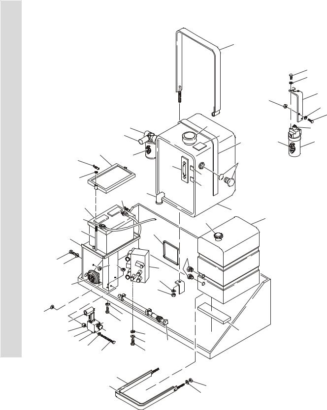
FIGURE 2-1. CONTROL VALVES & TANKS INSTALLATION
4
34
35
19
32
16
31
|
|
3 |
|
2B |
|
21B |
|
|
|
45 |
|
||
|
|
3B |
|
21A |
|
|
|
|
|
|
10 |
21 |
|
|
24 |
3A |
|
|
|
|
27 |
|
|
43 |
|
|
|
|
|
|
|
|
||
|
|
|
|
2A |
NOTE: LOCATED |
|
|
|
|
|
|
||
8 |
|
|
|
47 |
IN ENGINE TRAY |
|
|
|
|
|
|
||
|
|
|
|
|
|
|
|
|
|
2C |
48 |
|
|
|
|
41 |
|
|
|
|
25 |
|
|
|
|
|
|
|
|
|
|
|
|
|
23 |
|
|
|
2 |
|
|
|
|
|
|
|
|
|
42 |
|
|
|
1A |
1 |
|
|
|
|
|
|
|
|
26 |
|
|
44 |
|
|
|
|
|
|
|
|
|
|
20 |
|
|
|
|
|
|
31 |
|
|
|
46 |
|
|
32 |
|
|
|
|
||
16 |
|
18 |
|
|
||
|
|
|
|
|
|
|
38 |
|
|
8 |
|
|
|
39 |
|
|
|
|
|
|
|
|
|
|
|
|
|
40 |
|
|
7 |
|
|
|
35 |
|
|
|
|
|
|
32 |
|
16 |
|
|
|
|
22A |
22B |
|
|
|
|
|
31 |
|
|
|
|
||
37 |
22C |
|
17 |
11 |
|
|
22 |
|
|
16 |
|
|
|
22D |
|
|
28 |
|
|
|
50 |
|
|
|
|
|
|
33 |
|
15 |
29 |
|
|
|
|
|
|
|
|||
|
|
|
|
30 |
|
|
|
|
|
|
36 |
|
|
|
5 |
|
|
|
|
|
|
10 |
|
|
7 |
|
|
|
|
|
|
|
|
|
|
|
|
|
8 |
|
|
2-2 |
3120893 |

SECTION 2 GROUND COMPONENTS
.
FIGURE 2-1. CONTROL VALVES & TANKS INSTALLATION
FIG & ITEM # |
PART NUMBER |
DESCRIPTION |
QTY. |
REV. |
|
|
|
|
|
|
0256120 |
VALVES & TANKS INSTALLATION |
Ref. |
13 |
1 |
|
Tank, Fuel Options: |
1 |
|
|
4400371 |
Prior to S/N 37163 |
|
|
|
4400401 |
S/N 37163 to Present |
|
|
1A |
1120477 |
Cap, Fuel |
1 |
|
2 |
4400383 |
Hydraulic Tank Assembly |
1 |
|
2A |
7014802 |
Gauge, Sight |
1 |
|
2B |
7014803 |
Breather/Filler |
1 |
|
2C |
7026544 |
Elbow, W/Drain Plug |
1 |
|
3 |
2120157 |
Filter, Oil Return |
1 |
|
3A |
2120158 |
Element, Filter |
1 |
|
3B |
7016313 |
Switch, Pressure |
1 |
|
4 |
4240118 |
Strap, Hold-Down (Hydraulic Tank) |
1 |
|
5 |
4240117 |
Strap, Hold-Down (Fuel Tank) |
1 |
|
6 |
Not Used |
|
|
|
7 |
3311601 |
Nut 3/8”-16NC |
5 |
|
8 |
4751600 |
Flatwasher 3/8” |
7 |
|
9 |
0100011 |
Loctite #242 (Not Shown) |
A/R |
|
10 |
|
Molding Options: |
|
|
|
4280295 |
Strip, Bumper (Prior to S/N 37163) |
5ft/1.5m |
|
|
4420037 |
Molding, Rubber 1” (S/N 37163 to Present) |
7ft/2.1m |
|
11 |
4420038 |
Molding, Rubber 2” |
2ft/0.6m |
|
12 to 14 |
Not Used |
|
|
|
15 |
0641506 |
Bolt 5/16”-18NC x 3/4” |
3 |
|
16 |
4751500 |
Flatwasher 5/16” |
13 |
|
17 |
4761500 |
Lockwasher 5/16” |
3 |
|
18 |
4640977 |
Control Valve Assembly (See Figure 2-2 for Breakdown) |
1 |
|
19 |
0902289 |
Bracket, Mounting - Filter |
1 |
|
20 |
4845337 |
Bracket, Mounting - Battery |
1 |
|
21 |
2120146 |
Filter, Oil - Pressure |
1 |
|
21A |
2120150 |
Element, Filter |
1 |
|
21B |
7016312 |
Switch, Indicator |
1 |
|
22 |
4640859 |
Manual Descent Valve Assembly |
1 |
|
22A |
7012952 |
Cartridge, Pump |
1 |
|
22B |
7012954 |
Cartridge, Needle Valve |
1 |
|
|
7012953 |
Seal Kit - 7012954 Cartridge |
1 |
|
22C |
7012961 |
Knob |
1 |
|
22D |
7012955 |
Cartridge, Check |
1 |
|
|
7012940 |
Seal Kit - 7012955 Cartridge |
1 |
|
23 |
0400003 |
Battery |
1 |
|
24 |
0400002 |
Hold-Down, Battery |
1 |
|
24A |
2910479 |
Clips, Hold-Down (Not Shown) |
4 |
|
25 |
3980003 |
Seat, Battery |
1 |
|
26 |
0630370 |
Rod, Tie-Down |
2 |
|
27 |
3300029 |
Wingnut 3/8”-16NC |
2 |
|
28 |
2560123 |
Grip, Handle |
1 |
|
29 |
2560122 |
Handle, Manual Descent Valve |
1 |
|
|
|
|
|
|
S E C T I O N
2
G R O U N D
C O M P O N E N T S
3120893 |
2-3 |

S E C T I O N
2
G R O U N D
C O M P O N E N T S
SECTION 2 GROUND COMPONENTS
FIGURE 2-1. CONTROL VALVES & TANKS INSTALLATION (CONTINUED)
FIG & ITEM # |
PART NUMBER |
DESCRIPTION |
QTY. |
REV. |
|
|
|
|
|
30 |
1380136 |
Clip, Mounting |
2 |
|
31 |
0641508 |
Bolt 5/16”-18NC x 1” |
5 |
|
32 |
3311505 |
Locknut 5/16”-18NC |
7 |
|
33 |
0641530 |
Bolt 5/16”-18NC x 3 3/4” |
2 |
|
34 |
0651404 |
Bolt 1/4”-28NF x 1/2” |
2 |
|
35 |
4711400 |
Flatwasher 1/4” (Narrow) |
2 |
|
36 |
3820019 |
Rivet |
2 |
|
37 |
4566987 |
Tube, Spacer |
2 |
|
38 |
0140001 |
Horn |
1 |
|
39 |
0641406 |
Bolt 1/4”-20NC x 3/4” |
1 |
|
40 |
3311405 |
Locknut 1/4”-20NC |
1 |
|
41 |
1060360 |
Cable, Battery (Battery to Ground) |
1 |
|
42 |
1060632 |
Cable, Battery (Battery to Starter Relay) |
1 |
|
43 |
2220240 |
Plug, O-Ring |
2 |
|
44 |
4060807 |
Flex-Trim |
9ft/2.7m |
|
45 |
1701504 |
Decal - Hydraulic Fluid |
1 |
|
46 |
3300233 |
Plug, O-Ring |
2 |
|
47 |
1701502 |
Hydraulic Oil Level (High) |
1 |
|
48 |
1701503 |
Hydraulic Oil Level (Low) |
1 |
|
49 |
0100001 |
Adhesive (Not Shown) |
A/R |
|
50 |
4711500 |
Flatwasher (Narrow) (S/N 62148 to Present) |
4 |
|
|
|
|
|
|
2-4 |
3120893 |

SECTION 2 GROUND COMPONENTS
FIGURE 2-1. CONTROL VALVES & TANKS INSTALLATION (CONTINUED)
FIG & ITEM # PART NUMBER |
DESCRIPTION |
QTY. REV. |
S |
|
|
|
|
|
|
|
|
|
|
|
E |
|
|
|
C |
|
|
|
T |
|
|
|
I |
|
|
|
O |
|
|
|
N |
2
G
R
O
U
N
D
C
O
M
P
O
N
E
N
T
S
3120893 |
2-5 |
S E C T I O N
2
G R O U N D
C O M P O N E N T S
SECTION 2 GROUND COMPONENTS
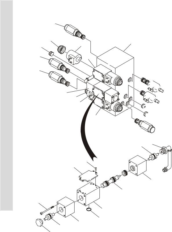
FIGURE 2-2. CONTROL VALVES ASSEMBLY
|
4 |
|
9A |
6 |
9B |
|
|
5 |
9 |
|
|
3 |
|
8
10A
10B
106
113
101
105
110
108 109A
111
1

 7
7


 2
2

 6
6
 12
12
 5
5
108 112
109
 11
11
 110 103
104
102
104
2-6 |
3120893 |

SECTION 2 GROUND COMPONENTS
.
FIGURE 2-2. CONTROL VALVES ASSEMBLY
FIG & ITEM # |
PART NUMBER |
DESCRIPTION |
QTY. |
REV. |
|
|
|
|
|
|
4640977 |
CONTROL VALVE ASSEMBLY |
Ref. |
C |
1 |
Not Serviced |
Manifold |
1 |
|
2 |
7012966 |
Cartridge With Coil |
1 |
|
|
7012967 |
Seal Kit - 7012966 Cartridge |
1 |
|
|
7012944 |
Coil |
1 |
|
3 |
7017415 |
Cartridge |
1 |
|
|
7012998 |
Seal Kit - 7017415 Cartridge |
1 |
|
4 |
7017416 |
Cartridge |
1 |
|
|
7012998 |
Seal Kit - 7017416 Cartridge |
1 |
|
5 |
7017417 |
Cartridge |
2 |
|
|
7012998 |
Seal Kit - 7017417 Cartridge (1 Per Cartridge) |
2 |
|
6 |
7018900 |
Orifice 1/16”/1.2mm |
2 |
|
7 |
7012941 |
Cartridge Less Coil |
1 |
|
|
7010543 |
Seal Kit - 7012941 Cartridge |
1 |
|
|
7012944 |
Coil |
1 |
|
8 |
7018901 |
Valve Assembly (See Items 101-113 for Breakdown) |
1 |
|
9 |
7012770 |
Valve Assembly |
1 |
|
|
7012773 |
Seal Kit |
2 |
|
9A |
7018912 |
Nut |
2 |
|
9B |
7012772 |
Coil |
2 |
|
10 |
7012795 |
Valve Assembly |
1 |
|
|
7012773 |
Seal Kit |
2 |
|
10A |
7018912 |
Nut |
2 |
|
10B |
7012772 |
Coil |
2 |
|
11 |
7018903 |
Tube Assembly |
1 |
|
12 |
7018905 |
Plug |
1 |
|
|
7018901 |
VALVE ASSEMBLY |
Ref. |
|
101 |
Not Serviced |
Housing |
1 |
|
102 |
7018911 |
Spool |
1 |
|
103 |
Not Serviced |
Detent |
1 |
|
104 |
7018906 |
O-Ring |
2 |
|
105 |
7018907 |
O-Ring |
4 |
|
106 |
Not Serviced |
Nameplate |
1 |
|
107 |
Not Serviced |
Rivet |
4 |
|
108 |
7018908 |
O-Ring |
2 |
|
109 |
7018909 |
Spool |
1 |
|
109A |
7018910 |
Pin, Push |
1 |
|
110 |
Not Serviced |
Housing |
2 |
|
111 |
Not Serviced |
Plug |
1 |
|
112 |
7018904 |
Fitting 90° |
1 |
|
113 |
Not Serviced |
Capscrew, Socket Head M4 x 45mm |
8 |
|
|
|
|
|
|
S E C T I O N
2
G R O U N D
C O M P O N E N T S
3120893 |
2-7 |

8-2
3120893
S E C T I O N 2 G R O U N D C O M P O N E N T S
|
|
|
|
2 |
|
|
|
|
|
|
|
|
|
|
|
|
|
|
|
|
45 |
|
|
|
|
|
|
|
|
|
|
|
|
|
|
|
|
46 |
12 |
|
|
|
|
|
|
|
|
|
|
|
|
|
|
|
|
22 |
11D |
|
|
|
|
|
|
|
|
|
|
|
|
|
|
|
23 |
11B |
|
|
|
|
|
|
|
|
|
|
|
|
|
|
11A |
|
|
|
|
|
|
|
|
|
|||
|
|
|
|
|
|
|
|
|
|
|
|
|
|
|
||
|
|
|
|
|
|
|
11C |
|
|
|
|
|
31 |
|
|
|
6 |
|
|
|
|
|
|
|
|
|
|
|
|
|
|
||
|
|
|
11 |
|
|
|
13 |
|
49 |
|
|
|
|
|
|
|
|
|
|
5 |
|
|
|
|
|
|
|
|
|
|
|||
|
|
|
|
|
|
|
|
|
|
|
|
|
|
|
||
|
|
|
|
|
|
|
|
|
|
|
|
|
|
|
|
|
44 |
|
|
|
45 |
|
|
|
4 |
|
|
|
|
|
|
|
|
|
|
|
46 |
|
|
|
|
19 |
|
|
|
|
|
|
||
84 |
|
|
|
|
45 |
|
|
|
|
|
|
INSTALL BETWEEN STARTER |
|
|
||
|
|
|
|
|
|
|
|
|
|
104 |
|
MTG BOLT AND ENGINE MTG |
|
|
||
|
|
|
|
|
|
|
|
|
|
|
67 BOLT TO TRAY |
|
|
|||
|
|
|
|
|
|
|
|
106 101B |
|
107 |
|
|
|
|
|
|
|
|
|
|
|
|
|
126 |
|
|
|
121 |
127 |
77 |
|
|
|
|
|
|
|
|
|
|
|
101C |
|
|
|
|
128 |
78 |
|
|
42 |
|
|
|
|
|
|
|
101 |
|
|
|
|
|
79 |
|
|
43 |
|
|
|
|
|
|
|
|
|
|
|
|
17 |
|
|
|
|
|
|
|
|
|
|
132 |
|
|
|
|
|
|
|
||
|
|
|
|
|
|
|
|
|
|
|
|
124 |
|
|
||
|
|
|
|
|
|
|
|
101A |
|
|
|
|
114 |
|
|
|
|
|
|
|
|
|
|
|
|
|
|
|
|
|
|
|
|
|
|
|
|
|
|
|
69 |
82 |
|
|
|
|
|
|
|
|
|
|
|
|
|
|
|
83 |
|
|
|
|
|
|
|
|
|
|
|
|
|
|
|
|
70 |
|
|
|
|
|
|
|
|
|
|
|
|
|
36 |
|
|
20 |
|
|
|
|
|
|
123 |
|
|
|
|
|
|
22 |
|
|
68 |
|
|
|
|
|
|
|
|
|
|
|
|
|
23 |
|
|
23 |
103 |
|
|
|
|
|
129 |
80 |
81 |
|
|
|
|
|
|
|
36 |
|
|
|
|
|
|
|
||
|
|
|
|
|
|
36 |
112 |
|
|
|
|
|
|
|
1 |
|
|
|
|
|
29 |
|
86 |
|
|
|
|
|
|
|
|||
|
|
|
|
35 |
40 |
|
|
|
|
|
|
|
|
|||
|
|
|
|
|
|
|
41 |
|
|
|
|
|
125 |
|
|
|
|
|
|
|
|
|
|
|
105 |
|
|
|
|
|
115 |
|
|
|
|
|
|
|
|
|
|
|
|
|
|
|
|
|
|
|
|
|
|
|
|
|
|
|
7 |
122 |
|
|
|
|
|
|
73 |
|
|
|
|
|
|
|
|
|
|
|
|
|
|
75 |
||
|
|
|
|
|
10 |
|
24 |
8 |
|
|
|
|
|
|
|
|
|
|
|
|
|
|
|
|
|
|
|
|
|
|
|
||
|
|
|
|
|
|
26 |
|
|
|
|
|
|
|
|
|
|
|
|
|
|
|
|
25 |
|
|
|
|
|
|
|
|
|
|
|
|
|
|
|
|
27 |
34 |
36 |
|
|
|
|
|
|
|
|
|
|
|
|
|
|
33 |
|
|
|
|
|
|
|
|
|
|
|
|
4 |
|
|
|
|
|
35 |
|
|
|
|
|
|
|
|
|
|
0 |
|
|
|
|
|
71 |
|
|
33 |
|
|
|
74 |
|
|
|
|
|
|
|
|
|
|
|
|
|
10 |
|
|
75 |
|
50 |
|
|
|
|
|
|
|
|
|
|
|
|
|
|
|
|
|
|
|
|
|
|
|
|
|
|
|
24 |
|
|
|
||
51 |
85 |
|
|
|
|
|
|
|
|
9 |
26 |
|
|
|
||
52 |
|
|
|
|
|
|
|
|
25 |
|
|
|
||||
|
116 |
|
|
|
|
|
|
|
|
27 |
34 |
|
47 |
|
||
|
|
|
|
|
|
|
|
|
|
|
|
|
|
|
|
|
118 |
|
|
|
|
|
|
|
|
32 |
119 |
|
|
|
|
41 |
|
|
|
|
|
|
|
|
|
|
|
|
|
|
|
|||
|
51 |
|
|
|
|
|
|
|
|
|
|
|
|
|
||
87 |
|
|
|
|
|
|
|
|
|
|
|
|
|
24 |
|
|
41 |
|
|
64 |
|
|
|
|
|
|
|
|
|
|
|
||
|
|
|
|
FUEL TANK |
|
|
|
|
|
|
|
|
|
|
||
|
|
|
|
65 |
|
|
|
|
|
|
|
|
|
21 |
||
|
|
|
|
|
LOCATED IN |
|
|
|
|
|
|
|
|
|
||
|
|
|
|
|
|
|
|
|
|
|
|
|
|
|
||
HYDRAULIC TRAY
130
59
51 

 53
53


30


57 


 51 56
51 56  48
48
53
76 |
29 |
131 |
|
72
60
61
62
16
66
38
2336
39
3
48113) S/N TO (PRIOR INSTALLATION ENGINE GAS VANGUARD .3-2 FIGURE
COMPONENTS GROUND 2 SECTION

SECTION 2 GROUND COMPONENTS
.
FIGURE 2-3. VANGUARD GAS ENGINE INSTALLATION (PRIOR TO S/N 48113)
FIG & ITEM # |
PART NUMBER |
DESCRIPTION |
QTY. |
REV. |
|
|
|
|
|
|
0255959 |
VANGUARD ENGINE ASSEMBLY & INSTALLATION (PRIOR |
Ref. |
14 |
|
|
TO S/N 48113) |
|
|
1 |
3539676 |
Shroud, Fan |
1 |
|
2 |
1340033 |
Cap, Air Intake |
1 |
|
3 |
3539465 |
Plate, Mounting (Radiator) |
1 |
|
4 |
2000140 |
Engine - Vanguard DM700G (See Items 101-130 for Break- |
1 |
|
|
|
down) |
|
|
5 |
3600256 |
Piston Pump Assembly (See Figure 2-7 for Breakdown) |
1 |
|
6 |
See Note |
Gear Pump Assembly (was p/n 3600257) |
1 |
|
|
|
Note: P/N 3600257 no longer available. Use p/n 3600466. |
Ref. |
|
|
|
New pump includes required fitting. |
|
|
|
7018924 |
Seal Kit (Includes Shaft Seal) |
1 |
|
|
7018923 |
Seal, Shaft |
1 |
|
7 |
3539459 |
Plate, Mounting (Rear Right Side) |
1 |
|
8 |
3539460 |
Plate, Mounting (Rear Left Side) |
1 |
|
9 |
3539461 |
Plate, Mounting (Front) |
1 |
|
10 |
3200381 |
Mount, Motor |
3 |
|
11 |
1340057 |
Air Cleaner Assembly |
1 |
|
11A |
7015004 |
Element, Filter |
1 |
|
11B |
7015005 |
Cover Assembly |
1 |
|
11C |
7015006 |
Valve, Vacuator |
1 |
|
11D |
7015007 |
Latch |
2 |
|
12 |
0340045 |
Band, Mounting |
1 |
|
13 |
3539484 |
Plate, Mounting (Air Cleaner) |
1 |
|
14 to 15 |
Not Used |
|
|
|
16 |
3620035 |
Radiator |
1 |
|
|
7016606 |
Cap, Radiator |
1 |
|
|
7019618 |
Draincock |
1 |
|
17 |
2901414 |
Fan Kit |
1 |
|
18 |
1700430 |
Decal - Gas (Not Shown - Located on Hood) |
1 |
|
19 |
4567104 |
Pipe, Exhaust |
1 |
|
20 |
0902270 |
Bracket |
1 |
|
21 |
2540032 |
Grommet |
2 |
|
22 |
0641506 |
Bolt 5/16”-18NC x 3/4” |
2 |
|
23 |
3311505 |
Locknut 5/16”-18NC |
5 |
|
24 |
0641608 |
Bolt 3/8”-16NC x 1” |
7 |
|
25 |
3311605 |
Locknut 3/8”-16NC |
6 |
|
26 |
0641818 |
Bolt 1/2”-13NC x 2 1/4” |
3 |
|
27 |
3311805 |
Locknut 1/2”-13NC |
3 |
|
28 |
Not Used |
|
|
|
29 |
Use 2910000 |
Actuator Assembly (Was p/n 0060037) (See Section 7 for |
1 |
|
|
|
Breakdown) |
|
|
30 |
3841315 |
Rod, Throttle |
1 |
|
31 |
3220109 |
Muffler |
1 |
|
32 |
|
|
|
|
33 |
4740274 |
Washer, Snubbing |
3 |
|
34 |
4751600 |
Flatwasher 3/8” |
6 |
|
35 |
0700810 |
Bolt Metric 8mm x 20mm |
12 |
|
|
|
|
|
|
S E C T I O N
2
G R O U N D
C O M P O N E N T S
3120893 |
2-9 |

S E C T I O N
2
G R O U N D
C O M P O N E N T S
SECTION 2 GROUND COMPONENTS
FIGURE 2-3. VANGUARD GAS ENGINE INSTALLATION (PRIOR TO S/N 48113) (CONTINUED)
FIG & ITEM # |
PART NUMBER |
DESCRIPTION |
QTY. |
REV. |
|
|
|
|
|
36 |
4751500 |
Flatwasher 5/16” |
23 |
|
37 |
0100011 |
Loctite #242 (Not Shown) |
A/R |
|
38 |
0760605 |
Bolt, Metric 6mm x 10mm |
6 |
|
39 |
0641508 |
Bolt 5/16”-18NC x 1” |
3 |
|
40 |
2720015 |
Hose, Fuel Line (1/4”) |
6ft/1.8m |
|
41 |
1320022 |
Clamp, Hose |
8 |
|
42 |
0641812 |
Bolt 1/2”-13NC x 1 1/2” |
2 |
|
43 |
4751800 |
Flatwasher 1/2” |
2 |
|
44 |
0701012 |
Bolt, Metric 10mm x 25mm |
2 |
|
45 |
1320031 |
Clamp, Hose |
4 |
|
46 |
2720063 |
Hose, Air Intake |
2ft/0.6m |
|
47 |
|
Hose (3/8”) Options: |
|
|
|
2750532 |
Prior to S/N 44924 |
2ft/0.6m |
|
|
2720058 |
S/N 44924 to Present |
5ft/1.5m |
|
48 |
0651405 |
Bolt 1/4”-28NF x 5/8” |
1 |
|
49 |
1320026 |
Clamp, U-Bolt |
1 |
|
50 |
0641406 |
Bolt 1/4”-20NC x 3/4” |
5 |
|
51 |
4751400 |
Flatwasher 1/4” |
9 |
|
52 |
3311405 |
Locknut 1/4”-20NC |
3 |
|
53 |
4567086 |
Tube, Spacer - Throttle Linkage |
2 |
|
54 to 55 |
Not Used |
|
|
|
56 |
1660222 |
Coupling, Throttle |
1 |
|
57 |
3321402 |
Nut, Jam 1/4”-28NF |
1 |
|
58 |
Not Used |
|
|
|
59 |
1660220 |
Coupling, Throttle |
1 |
|
60 |
4740442 |
Washer, Belleville |
1 |
|
61 |
3900217 |
Bolt, Socket Head Shoulder 3/8”-16NC x 7/8” |
1 |
|
62 |
0962031 |
Bushing, Flanged |
1 |
|
63 |
Not Used |
|
|
|
64 |
2220250 |
Fitting, Reducer |
1 |
|
65 |
2220317 |
° |
1 |
|
|
|
Fitting, 90 |
|
|
66 |
4811700 |
Flatwasher, Metric 6mm |
6 |
|
67 |
1060221 |
Cable, Solenoid |
1 |
|
68 |
3740049 |
Relay |
2 |
|
69 |
0721008 |
Bolt #10-24NC x 1” |
2 |
|
70 |
3311005 |
Locknut #10-24NC |
2 |
|
71 |
0700812 |
Bolt, Metric 8mm x 25mm |
3 |
|
72 |
3539929 |
Plate, Mounting |
1 |
|
73 |
2720420 |
Hose, Radiator (Top) |
1 |
|
74 |
2720421 |
Hose, Radiator (Bottom) |
1 |
|
75 |
|
Clamp, Hose Options: |
4 |
|
|
1320014 |
Prior to S/N 44432 |
|
|
|
1320033 |
S/N 44432 to Present |
|
|
76 |
4160150 |
Spring (Used Prior to S/N 28511 - Recommend #131 as |
1 |
|
|
|
replacement) |
|
|
77 |
1320061 |
Clamp, Hose |
1 |
|
78 |
0700808 |
Bolt, Metric 8mm x 16mm |
1 |
|
79 |
4751500 |
Flatwasher 5/16” |
1 |
|
|
|
|
|
|
2-10 |
3120893 |
Loading...