


 Loading...
Illustrated Parts Manual
Model 26MRT
P/N
3120792
October 17, 2013
REVISION LOG
February 4, 2000 - Original Issue Of Manual (Was part of complete Manual #3123003) (Edited to 0010520 Revision 37) October 30, 2000 - Revised (Edited to 0010520 Revision 37)
February 25, 2004 - Revised
September 15, 2007 - Revised
June 24, 2011 - Revised
October 17, 2013 - Revised
3120792 |
A |
REVISION LOG
B |
3120792 |
TABLE OF CONTENTS
FIGURE NO. |
TITLE |
PAGE NO. |
SECTION 1 - FRAME . . . . . . . . . . |
. . . . . . . . . . . . . . . . . . . . . . . . . . . . . . . . . . . . . . . . . |
. . .1-1 |
1-1 FRAME AND STEERING INSTALLATION . . . . . . . . . . . . . . . . . . . . . . . . . . . . . . . . . . . .1-2 1-2 REAR DRIVE INSTALLATION. . . . . . . . . . . . . . . . . . . . . . . . . . . . . . . . . . . . . . . . . . . . . .1-4 1-3 DRIVE MOTOR ASSEMBLY. . . . . . . . . . . . . . . . . . . . . . . . . . . . . . . . . . . . . . . . . . . . . . .1-8 1-4 DRIVE BRAKE ASSEMBLY . . . . . . . . . . . . . . . . . . . . . . . . . . . . . . . . . . . . . . . . . . . . . . .1-10 1-5 DRIVE AXLE ASSEMBLY . . . . . . . . . . . . . . . . . . . . . . . . . . . . . . . . . . . . . . . . . . . . . . . . .1-12 1-6 FRAME MOUNTED COMPONENTS INSTALLATION . . . . . . . . . . . . . . . . . . . . . . . . . . .1-14 1-7 HYDRAULIC DRIVE GENERATOR INSTALLATION. . . . . . . . . . . . . . . . . . . . . . . . . . . . .1-18
SECTION 2 - GROUND COMPONENTS . . . . . . . . . . . . . . . . . . . . . . . . . . . . . . . . . . . . . . .2-1
2-1 CONTROL VALVES & TANKS INSTALLATION . . . . . . . . . . . . . . . . . . . . . . . . . . . . . . . .2-2 2-2 CONTROL VALVES ASSEMBLY . . . . . . . . . . . . . . . . . . . . . . . . . . . . . . . . . . . . . . . . . . .2-6 2-3 VANGUARD GAS ENGINE INSTALLATION (PRIOR TO S/N 48113) . . . . . . . . . . . . . . .2-8 2-4 VANGUARD GAS ENGINE INSTALLATION (S/N 48113 TO PRESENT). . . . . . . . . . . . .2-14 2-5 DUAL FUEL INSTALLATION (VANGUARD MACHINES ONLY) . . . . . . . . . . . . . . . . . . .2-18 2-6 YANMAR DIESEL ENGINE INSTALLATION . . . . . . . . . . . . . . . . . . . . . . . . . . . . . . . . . .2-22 2-7 PISTON PUMP ASSEMBLY . . . . . . . . . . . . . . . . . . . . . . . . . . . . . . . . . . . . . . . . . . . . . .2-26 2-8 GEAR PUMP ASSEMBLY (YANMAR ENGINE) . . . . . . . . . . . . . . . . . . . . . . . . . . . . . . . .2-28 2-9 GROUND CONTROLS INSTALLATION . . . . . . . . . . . . . . . . . . . . . . . . . . . . . . . . . . . . . .2-30 2-10 HOOD INSTALLATIONS . . . . . . . . . . . . . . . . . . . . . . . . . . . . . . . . . . . . . . . . . . . . . . . . .2-36
SECTION 3 - SCISSOR ARMS. . . . . . . . . . . . . . . . . . . . . . . . . . . . . . . . . . . . . . . . . . . . . . .3-1
3-1 SCISSOR ARMS INSTALLATION . . . . . . . . . . . . . . . . . . . . . . . . . . . . . . . . . . . . . . . . . .3-2
SECTION 4 - PLATFORM. . . . . . . . . . . . . . . . . . . . . . . . . . . . . . . . . . . . . . . . . . . . . . . . . . .4-1
4-1 PLATFORM COMPONENTS INSTALLATION - MANUALLY OPERATED
EXTENSION . . . . . . . . . . . . . . . . . . . . . . . . . . . . . . . . . . . . . . . . . . . . . . . . . . . . . . . .4-2 4-2 STANDARD HANDRAILS & EXTENSION INSTALLATION (MANUALLY
OPERATED PLATFORM) . . . . . . . . . . . . . . . . . . . . . . . . . . . . . . . . . . . . . . . . . . . . . .4-6 4-3 WIDE PLATFORM HANDRAILS & EXTENSION INSTALLATION (MANUALLY
OPERATED PLATFORM) . . . . . . . . . . . . . . . . . . . . . . . . . . . . . . . . . . . . . . . . . . . . . .4-10 4-4 FOLDDOWN HANDRAILS & EXTENSION INSTALLATION (MANUALLY
OPERATED PLATFORM) . . . . . . . . . . . . . . . . . . . . . . . . . . . . . . . . . . . . . . . . . . . . . .4-14 4-5 PLATFORM CONSOLE BOX ASSEMBLY . . . . . . . . . . . . . . . . . . . . . . . . . . . . . . . . . . . .4-18 4-6 CONTROLLER ASSEMBLY (PRIOR TO S/N 58990) . . . . . . . . . . . . . . . . . . . . . . . . . . . .4-22 4-7 CONTROLLER ASSEMBLY (S/N 58990 TO PRESENT) . . . . . . . . . . . . . . . . . . . . . . . . .4-24
SECTION 5 - CYLINDERS . . . . . . . . . . . . . . . . . . . . . . . . . . . . . . . . . . . . . . . . . . . . . . . . . .5-1
5-1 LIFT CYLINDER COMPONENTS ASSEMBLY (PRIOR TO S/N 26916) . . . . . . . . . . . . .5-2 5-2 LIFT CYLINDER COMPONENTS ASSEMBLY (S/N 26916 TO PRESENT) . . . . . . . . . . .5-6 5-3 STEER CYLINDER ASSEMBLY . . . . . . . . . . . . . . . . . . . . . . . . . . . . . . . . . . . . . . . . . . . .5-10
SECTION 6 - HYDRAULIC . . . . . . . . . . . . . . . . . . . . . . . . . . . . . . . . . . . . . . . . . . . . . . . . . .6-1
6-1 HYDRAULIC DIAGRAM - STANDARD . . . . . . . . . . . . . . . . . . . . . . . . . . . . . . . . . . . . . . .6-2 6-2 HYDRAULIC DIAGRAM LIST . . . . . . . . . . . . . . . . . . . . . . . . . . . . . . . . . . . . . . . . . . . . . .6-6
3120792 |
i |
TABLE OF CONTENTS
FIGURE NO. |
TITLE |
PAGE NO. |
SECTION 7 - ELECTRICAL . . . . . . . . . . . . . . . . . . . . . . . . . . . . . . . . . . . . . . . . . . . . . . |
. . . 7-1 |
|
7-1 |
ELECTRICAL DIAGRAM LIST . . . . . . . . . . . . . . . . . . . . . . . . . . . . . . . . . . . . . . . . . |
. . . . 7-2 |
7-2 |
ELECTRICAL SCHEMATIC - VANGUARD . . . . . . . . . . . . . . . . . . . . . . . . . . . . . . |
. . . . 7-4 |
7-3 |
ELECTRICAL SCHEMATIC - YANMAR . . . . . . . . . . . . . . . . . . . . . . . . . . . . . . . . . . |
. . . 7-6 |
7-4 |
HARNESS AND CABLE ASSEMBLIES . . . . . . . . . . . . . . . . . . . . . . . . . . . . . . . . . . |
. . . 7-8 |
SECTION |
8 - DECALS . . . . . . . . . . . . . . . . . . . . . . . . . . . . . . . . . . . . . . . . . . . . . . . . . . . . . |
8-1 |
8-1 |
DECALS INSTALLATIONS . . . . . . . . . . . . . . . . . . . . . . . . . . . . . . . . . . . . . . . . . . . . . |
8-2 |
SECTION 9 - RECOMMENDED SERVICE PARTS STOCK . . . . . . . . . . . . . . . . . . . . . . . . 9-1 SECTION 10 - SPECIAL OPTIONS . . . . . . . . . . . . . . . . . . . . . . . . . . . . . . . . . . . . . . . . . . . 10-1
ii |
3120792 |
|
SECTION 1 FRAME |
|
|
|
|
|
|
|
S |
|
|
|
|
|
|
|
|
|
|
|
|
E |
|
|
TABLE OF CONTENTS |
|
|
|
|
|
|
|
|
C |
|
FIGURE |
DESCRIPTION |
PAGE |
|
T |
|
|
|
|
|||
|
|
|
|
I |
|
1-1 |
Frame And Steering Installation |
1-2 |
|
|
|
|
|
|
|||
1-2 |
Rear Drive Installation . . . . . . . . . . . . . . . . . . . . . . . . . . . . . . . . . . . . . . . . . . . . . . . . . . . . . |
. 1-4. . |
|
O |
|
1-3 |
Drive Motor Assembly . . . . . . . . . . . . . . . . . . . . . . . . . . . . . . . . . . . . . . . . . . . . . . . . . . . . . |
. 1-8. . |
|
|
|
1-4 |
Drive Brake Assembly . . . . . . . . . . . . . . . . . . . . . . . . . . . . . . . . . . . . . . . . . . . . . . . . . . . . . |
. 1-10. . |
|
N |
|
1-5 |
Drive Axle Assembly . . . . . . . . . . . . . . . . . . . . . . . . . . . . . . . . . . . . . . . . . . . . . . . . . . . . . . . |
. 1-12. . |
|
|
|
1-6 |
Frame Mounted Components Installation . . . . . . . . . . . . . . . . . . . . . . . . . . . . . . . . . . . . . . |
. 1-14. . |
|
1 |
|
1-7 |
Hydraulic Drive Generator Installation . . . . . . . . . . . . . . . . . . . . . . . . . . . . . . . . . . . . . . . . . |
. 1-18. . |
|
|
|
|
|
|
|
F |
|
|
|
|
|
R |
|
|
|
|
|
A |
|
|
|
|
|
M |
|
|
|
|
|
E |
|
|
|
|
|
|
|
|
|
|
|
|
|
3120792 |
1-1 |
S E C T I O N
1
F
R A M E
SECTION 1 FRAME
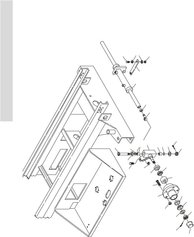
FIGURE 1-1. FRAME AND STEERING INSTALLATION
13 |
15 |
14 |
|
12 |
17 |
|
11 |
|
10
9
3 |
18 |
16 201 |
2 |
16 |
201 |
18 |
6 |
4 |
5 |
|
|
6 |
|
|
|
|
|
102 |
|
|
|
|
7 |
8 |
105 |
|
|
|
|
|
||
|
|
|
|
|
|
101 |
|
|
||
|
|
|
|
107 |
1 |
|
|
|
103 |
104 |
|
|
|
|
|
|
19 |
|
|
|
204 |
|
|
|
|
|
|
|
20 |
203 |
|
|
|
|
|
|
|
|
|
|
205 |
|
106 |
1-2 |
3120792 |

SECTION 1 FRAME
.
FIGURE 1-1. FRAME AND STEERING INSTALLATION
FIG & ITEM # |
PART NUMBER |
DESCRIPTION |
QTY. |
REV. |
|
|
|
|
|
|
|
FRAME WELDMENT OPTIONS: |
1 |
|
|
2360388 |
Prior to S/N 27658 |
|
|
|
2360413 |
S/N 27658 to Present |
|
|
|
0255118 |
STEERING & SPINDLES INSTALLATION |
Ref. |
8 |
1 |
2780221 |
Hub Assembly (Includes Items 101-107) |
2 |
|
2 |
4130286 |
Spindle Weldment (Includes Items 201-205) |
2 |
|
3 |
3422610 |
Kingpin |
2 |
|
4 |
3450810 |
Pin, Cotter 1/4” x 2 1/2” |
2 |
|
5 |
3313003 |
Nut, Slotted 1 1/4”-7NC |
2 |
|
6 |
0440162 |
Washer, Thrust |
2 |
|
7 |
0642016 |
Bolt 5/8”-16NC x 2” |
2 |
|
8 |
3312005 |
Locknut 5/8”-16NC |
2 |
|
9 |
3841146 |
Rod-End |
2 |
|
10 |
3322002 |
Nut, Jam 5/8”-16NC |
2 |
|
11 |
|
Steer Cylinder Assembly (See Section 5 For Breakdown) |
1 |
|
|
|
Options: |
|
|
|
1683239 |
Prior to S/N 46538 |
|
|
|
1683697 |
S/N 46538 to Present |
|
|
12 |
3340644 |
Pad, Wear |
1 |
|
13 |
0641508 |
Bolt 5/16”-18NC x 1” |
1 |
|
14 |
3311505 |
Locknut 5/16”-18NC |
1 |
|
15 |
4751500 |
Flatwasher 5/16” |
2 |
|
16 |
3020022 |
Grease |
A/R |
|
17 |
4070809 |
Shim |
A/R |
|
18 |
3780182 |
O-Ring |
4 |
|
19 |
|
Nut, Wheel Options: |
10 |
|
|
3300255 |
Prior to S/N 32539 |
|
|
|
3300407 |
S/N 32539 to Present |
|
|
20 |
4752200 |
Flatwasher 3/4” |
2 |
|
|
2780221 |
HUB ASSEMBLY |
Ref. |
|
101 |
7012519 |
Cup, Bearing - Inner (1 Per Hub) |
2 |
|
102 |
7012520 |
Cone, Bearing - Inner (1 Per Hub) |
2 |
|
103 |
7012521 |
Cup, Bearing - Outer (1 Per Hub) |
2 |
|
104 |
7012522 |
Cone, Bearing - Outer (1 Per Hub) |
2 |
|
105 |
7012523 |
Seal (1 Per Hub) |
2 |
|
106 |
7012524 |
Cap, Dust (1 Per Hub) |
2 |
|
107 |
7016360 |
Stud, Wheel (5 Per Hub) |
10 |
|
|
4130286 |
SPINDLE WELDMENT |
Ref. |
|
201 |
0961621 |
Bushing, Bronze (2 Per Spindle) |
4 |
|
202 |
Not Used |
|
|
|
203 |
7012542 |
Washer (1 Per Spindle) |
2 |
|
204 |
7012541 |
Nut, Slotted (1 Per Spindle) |
2 |
|
205 |
7012543 |
Pin, Cotter (1 Per Spindle) |
2 |
|
|
|
|
|
|
S E C T I O N
1
F
R A M E
3120792 |
1-3 |
|
SECTION 1 FRAME |
S |
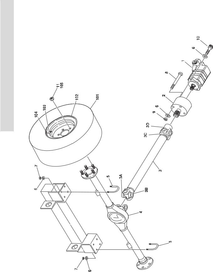
FIGURE 1-2. REAR DRIVE INSTALLATION |
E |
|
C |
|
T |
|
I |
|
O |
|
N |
|
1 |
|
F |
|
R |
|
A |
|
M |
|
E |
|
1-4 |
3120792 |
SECTION 1 FRAME
FIGURE 1-2. REAR DRIVE INSTALLATION
FIG & ITEM # |
PART NUMBER |
DESCRIPTION |
QTY. |
REV. |
|
|
|
|
|
|
|
REAR DRIVE AXLE INSTALLATION OPTIONS: |
Ref. |
|
|
0255113 |
Prior to S/N 27815 |
Ref. |
E |
|
0256927 |
S/N 27815 to Present |
Ref. |
3 |
1 |
3160202 |
Drive Motor Assembly (See Figure 1-3 for Break- |
1 |
|
|
|
down) |
|
|
2 |
0920103 |
Drive Brake Assembly (See Figure 1-4 for Break- |
1 |
|
|
|
down) |
|
|
3 |
1360265 |
Drive Shaft Assembly |
1 |
|
3A |
7011120 |
Journal & Bearing Kit |
2 |
|
3B |
7011121 |
U-Bolt Assembly |
1 |
|
3C |
7011122 |
Yoke |
2 |
|
3D |
7011123 |
Yoke, Splined |
1 |
|
4 |
|
Drive Axle Assembly Options: (See Figure 1-5 for |
1 |
|
|
|
Breakdown) |
|
|
|
0280148 |
Prior to S/N 27815 |
|
|
|
0280150 |
S/N 27815 to Present |
|
|
5 |
0630488 |
U-Bolt |
4 |
|
6 |
4711800 |
Flatwasher 1/2” (Narrow) |
14 |
|
7 |
3321805 |
Locknut 1/2”-20NF |
8 |
|
8 |
0641844 |
Bolt 1/2”-13NC x 5 1/2” |
4 |
|
9 |
3311805 |
Locknut 1/2”-13NC |
4 |
|
10 |
3931824 |
Capscrew, Socket Head 1/2”-13NC x 1 1/2” |
2 |
|
11 |
3300255 |
Nut, Wheel 1/2”-20NF |
10 |
|
12 |
0100011 |
Loctite #242 (Not Shown) |
A/R |
|
13 |
3020008 |
Lube, Gear (Not Shown) |
A/R |
|
14 |
1120064 |
Cap, Grease Fitting (Not Shown) |
2 |
|
|
|
TIRE AND WHEEL INSTALLATIONS OPTIONS: |
Ref. |
|
|
0255961 |
Standard Pneumatic (26 x 12.00) |
Ref. |
3 |
|
0256586 |
Lug Pneumatic (26 x 12.00) |
Ref. |
2 |
|
0257224 |
Pneumatic 27 x 10.50 - 15NHS |
Ref. |
2 |
|
0256694 |
Standard Foam Filled (26 x 12.00) |
Ref. |
2 |
|
0256696 |
Lug Foam Filled (26 x 12.00) |
Ref. |
2 |
|
|
Tire & Wheel Assembly Options: |
A/R |
|
|
4520168 |
26 x 12.00 Multi-Trac (Pneumatic) |
|
|
|
4520169 |
26 x 12.00 Tru-Power (Right Side) (Pneumatic) |
|
|
|
4520170 |
26 x 12.00 Tru-Power (Left Side) (Pneumatic) |
|
|
|
4520194 |
27 x 10.50 Lug Tread (Right Side) (Pneumatic) |
|
|
|
4520195 |
27 x 10.50 Lug Tread (Left Side) (Pneumatic) |
|
|
|
4520185 |
26 x 12.00 Multi-Trac (Foam Filled) |
|
|
|
4520186 |
26 x 12.00 Tru-Power (Right Side) (Foam Filled) |
|
|
|
4520187 |
26 x 12.00 Tru-Power (Left Side) (Foam Filled) |
|
|
|
|
|
|
|
S E C T I O N
1
F
R A M E
3120792 |
1-5 |

S E C T I O N
1
F
R A M E
SECTION 1 FRAME
FIGURE 1-2. REAR DRIVE INSTALLATION (CONTINUED)
FIG & ITEM # |
PART NUMBER |
DESCRIPTION |
QTY. |
REV. |
|
|
|
|
|
|
|
Note: Assemblies may require ballast/foam filling |
Ref. |
|
|
|
to manufacturer’s specifications prior to installing |
|
|
|
|
on a machine. Refer to Operation & Safety or Ser- |
|
|
|
|
vice & Maintenance Manuals. Purchase individual |
|
|
|
|
tire and/or rim only if able to foam fill tire & wheel |
|
|
|
|
assembly, otherwise, purchase complete assem- |
|
|
|
|
bly. |
|
|
|
|
TIRE AND WHEEL ASSEMBLY COMPONENTS |
Ref. |
|
101 |
|
Tire Options: |
A/R |
|
|
7018701 |
Tire - Multi Trac C/S 26 x 12.00 |
|
|
|
7018702 |
Tire - Tru Power TL 26 x 12.00 |
|
|
|
7020112 |
Tire - Lug Tread 27 x 10.50 |
|
|
102 |
|
Rim Options: |
A/R |
|
|
7018700 |
Rim - 12.00 |
|
|
|
7020113 |
Rim - 10.50 |
|
|
103 |
4640113 |
Valve, Air |
A/R |
|
104 |
1703067 |
Decal - Tire Pressure (40PSI) |
A/R |
|
105 |
3300407 |
Nut, Wheel 1/2*”-20NF (S/N 44598 to Present) |
10 |
|
|
|
|
|
|
1-6 |
3120792 |
|
|
SECTION 1 FRAME |
|
|
|
S |
|
FIGURE 1-2. REAR DRIVE INSTALLATION (CONTINUED) |
|
|
|
|
|||
|
|
|
|
|
|
E |
|
FIG & ITEM # |
PART NUMBER |
DESCRIPTION |
QTY. |
REV. |
|
C |
|
|
|
|
|||||
|
|
|
|
|
|
T |
|
|
|
|
|
|
|
|
|
|
|
|
|
|
|
I |
|
|
|
|
|
|
|
O |
|
|
|
|
|
|
|
N |
|
|
|
|
|
|
|
1 |
|
|
|
|
|
|
|
F |
|
|
|
|
|
|
|
R |
|
|
|
|
|
|
|
A |
|
|
|
|
|
|
|
M |
|
|
|
|
|
|
|
E |
|
|
|
|
|
|
|
|
|
|
|
|
|
|
|
|
|
3120792 |
1-7 |

S E C T I O N
1
F
R A M E
SECTION 1 FRAME
FIGURE 1-3. DRIVE MOTOR ASSEMBLY
|
20 |
|
|
1 |
|
|
16 |
|
|
17 |
|
|
2 |
|
|
|
5 |
|
18 |
4 |
|
|
|
15 |
|
3 |
|
24 |
|
|
2 |
|
|
22 |
|
|
19 |
|
|
2 |
|
21 |
42 |
44 |
37 |
||
|
41 |
|
|
40 |
|
13 |
14 |
11 |
|
|
|
|
26 |
||
14 |
|
12 |
6 |
|
|
|
|
25 27 |
|
|
|
|
|
|
|
|
10 |
|
|
|
|
9 |
|
39 |
|
|
|
|
|
|
|
|
|
24 |
|
|
|
43 |
38 |
|
|
|
7 |
|
1-8 |
3120792 |

SECTION 1 FRAME
.
FIGURE 1-3. DRIVE MOTOR ASSEMBLY
FIG & ITEM # |
PART NUMBER |
DESCRIPTION |
QTY. |
REV. |
|
|
|
|
|
|
3160202 |
DRIVE MOTOR ASSEMBLY |
Ref. |
A |
1 |
7014901 |
Shaft Sub-Assembly |
1 |
|
2 |
Kit |
Seal |
3 |
|
3 |
7014902 |
Plate, Valve |
1 |
|
4 |
Kit |
Seal |
1 |
|
5 |
7014903 |
Valve |
1 |
|
6 |
7009913 |
Spring, Compression |
2 |
|
7 |
7014904 |
Ring, Balance |
1 |
|
8 |
|
Pin, Spring (Part of Item #7) |
2 |
|
9 |
Kit |
O-Ring |
1 |
|
10 |
Kit |
Ring, Back-Up |
1 |
|
11 |
Kit |
O-Ring |
1 |
|
12 |
Kit |
Ring, Back-Up |
1 |
|
13 |
Kit |
O-Ring |
1 |
|
14 |
Kit |
Ring, Back-Up |
2 |
|
15 |
Kit |
Seal, Dust |
1 |
|
16 |
Kit |
Seal, Shaft |
1 |
|
17 |
Kit |
Ring, Back-Up |
1 |
|
18 |
7009918 |
Housing, Bearing |
1 |
|
19 |
7009979 |
Drive |
1 |
|
20 |
Kit |
Seal, Face |
1 |
|
21 |
7014905 |
Plate, Wear |
1 |
|
22 |
7009980 |
Geroler Assembly |
1 |
|
23 |
7009905 |
Drive, Valve |
1 |
|
24 |
Not Serviced |
Housing, Valve |
1 |
|
25 |
7000191 |
Ball, Steel |
2 |
|
26 |
7002159 |
Plug/O-Ring Assembly |
2 |
|
27 |
7000192 |
Spring, Compression |
2 |
|
28 to 36 |
Not Used |
|
|
|
37 |
7002157 |
Plug/O-Ring Assembly |
1 |
|
38 |
7014906 |
Plug/O-Ring Assembly |
1 |
|
39 |
7014907 |
Spool, Control |
1 |
|
40 |
7014908 |
Spring, Compression |
1 |
|
41 |
7014909 |
Spring, Compression |
1 |
|
42 |
7014910 |
Plug/O-Ring Assembly |
1 |
|
43 |
Kit |
Seal |
1 |
|
44 |
Not Serviced |
Bolt |
4 |
|
45 |
7009940 |
Plug/O-Ring Assembly (Not Shown) |
1 |
|
|
7014911 |
Seal Kit (Includes Items 2, 4, 9-14, 20, 43 & O-Rings on Plug |
|
|
|
|
Assemblies) |
|
|
|
|
|
|
|
S E C T I O N
1
F
R A M E
3120792 |
1-9 |

S E C T I O N
1
F
R A M E
SECTION 1 FRAME
FIGURE 1-4. DRIVE BRAKE ASSEMBLY
14
3 13
2 4
|
5 |
15 |
|
|
|
|
19 |
24 |
16 |
|
|
|
|
17
18
1
|
20 |
|
|
7 |
|
21 |
|
22 |
|
23 |
|
31 |
|
|
8 |
|
9 |
|
11 |
|
|
6 |
|
|
|
|
|
|
20 |
|
10 |
|
12
1-10 |
3120792 |

SECTION 1 FRAME
.
FIGURE 1-4. DRIVE BRAKE ASSEMBLY
FIG & ITEM # |
PART NUMBER |
DESCRIPTION |
QTY. |
REV. |
|
|
|
|
|
|
0920103 |
DRIVE BRAKE ASSEMBLY |
Ref. |
|
1 |
7011740 |
Shaft |
1 |
|
2 |
7011739 |
Plate, Cover |
1 |
|
3 |
7007941 |
Bearing |
1 |
|
4 |
Kit |
Seal, Oil |
1 |
|
5 |
7011738 |
Spline, Outer |
1 |
|
6 |
7007937 |
Capscrew, Socket Head |
4 |
|
7 |
7011737 |
Plate, Spring |
1 |
|
8 |
7011736 |
Piston |
1 |
|
9 |
Kit |
Ring, Back-Up |
1 |
|
10 |
7009774 |
Screw, Bleeder |
1 |
|
11 |
Kit |
O-Ring |
1 |
|
12 |
7011735 |
Plate, Pressure |
1 |
|
13 |
7011734 |
Ring, Retainer |
1 |
|
14 |
7007943 |
Ring, Retainer |
1 |
|
15 |
7007954 |
Ring, Retainer |
1 |
|
16 |
Kit |
Primary |
1 |
|
17 |
Kit |
Rotor |
5 |
|
18 |
Kit |
Stator |
4 |
|
19 |
7018601 |
Bolt, Shoulder |
4 |
|
20 |
Kit |
Seal, Case |
2 |
|
21 |
Kit |
Spring (Red) |
4 |
|
22 |
Kit |
Ring, Back-Up |
1 |
|
23 |
Kit |
O-Ring |
1 |
|
24 |
7018600 |
Capscrew, Socket Head |
2 |
|
25 to 29 |
Not Used |
|
|
|
30 |
7011710 |
Gasket (Not Shown) |
1 |
|
31 |
Kit |
Spring (Blue) |
2 |
|
|
7011741 |
Lining Repair Kit (Includes Items 16, 17, 18, 20 & 30) |
1 |
|
|
7011742 |
Bearing Repair Kit (Includes Items 3, 4, 20 & 30) |
1 |
|
|
7011743 |
O-Ring Repair Kit (Includes Items 4, 9, 11, 20, 22, 23 & 30) |
1 |
|
|
7011744 |
Spring Repair Kit (Includes Items 20, 21, 30 & 31) |
1 |
|
|
|
|
|
|
S E C T I O N
1
F
R A M E
3120792 |
1-11 |

S E C T I O N
1
F
R A M E
SECTION 1 FRAME
FIGURE 1-5. DRIVE AXLE ASSEMBLY
12
11 |
10 |
9 |
|
8 |
|
7 |
5 |
|
6 |
4

 3
3
1
|
|
|
2 |
32 |
30 |
|
|
33 |
|
|
|
34 |
|
|
|
35 |
23 |
39 |
15 |
36 |
|
21 |
|
|
20 |
|
14 |
31 |
39 |
|
|
37 |
|
|
|
|
18 |
17 |
16 |
38 |
|
19 |
|
1-12 |
3120792 |

SECTION 1 FRAME
.
FIGURE 1-5. DRIVE AXLE ASSEMBLY
FIG & ITEM # |
PART NUMBER |
DESCRIPTION |
QTY. |
REV. |
|
|
|
|
|
|
|
DRIVE AXLE ASSEMBLY OPTIONS: |
Ref. |
|
|
0280148 |
Prior to S/N 27815 |
Ref. |
|
|
0280150 |
S/N 27815 to Present |
Ref. |
|
1 |
7019033 |
Housing |
1 |
|
2 |
7019000 |
Drive Gear & Pinion |
1 |
|
3 |
7019001 |
Bearing, Inner Pinion |
1 |
|
4 |
Kit |
Shim, Drive Pinion Adjusting |
A/R |
|
5 |
7019003 |
Baffle, Pinion Bearing |
1 |
|
6 |
Kit |
Shim, Pinion Bearing Adjusting |
A/R |
|
7 |
7019004 |
Bearing, Outer Pinion |
1 |
|
8 |
7019005 |
Slinger, Outer Pinion Bearing |
1 |
|
9 |
7019006 |
Seal, Pinion |
1 |
|
10 |
7019007 |
Yoke Assembly |
1 |
|
11 |
7019008 |
Washer, Pinion Nut |
1 |
|
12 |
7019009 |
Nut, Pinion |
1 |
|
13 |
Not Used |
|
|
|
14 |
7019010 |
Cover, Carrier |
1 |
|
15 |
7019011 |
Gasket |
1 |
|
|
7019012 |
Sealant (Not Shown) |
A/R |
|
16 |
7019013 |
Plug |
1 |
|
17 |
7019014 |
Bolt, Carrier Cover |
10 |
|
18 |
7019015 |
Cap, Differential Bearing |
2 |
|
19 |
7019016 |
Bolt, Differential Bearing Cap |
4 |
|
20 |
7019017 |
Bearing, Differential |
2 |
|
21 |
Kit |
Shim, Differential Bearing |
A/R |
|
22 |
Not Used |
|
|
|
23 |
7019019 |
Bolt, Differential Case |
10 |
|
24 to 29 |
Not Used |
|
|
|
30 |
7019020 |
Bolt, Axle Shaft |
8 |
|
31 |
7019021 |
Nut, Axle Shaft |
8 |
|
32 |
7019022 |
Seal, Inboard Shaft |
2 |
|
33 |
7019023 |
Ring, Wheel Bearing Retaining |
2 |
|
34 |
7019024 |
Bearing, Axle Shaft Wheel |
2 |
|
35 |
7019025 |
Seal, Outboard Shaft |
2 |
|
36 |
7019026 |
Retainer, Axle Shaft |
2 |
|
37 |
7019027 |
Shaft, Axle |
2 |
|
38 |
7019034 |
Bolt, Wheel |
10 |
|
39 |
7019029 |
Differential & Case Assembly (Sold as an Assembly Only) |
1 |
|
|
7019002 |
Pinion & Bearing Adjusting Shims Kit (Includes Items 4, 6, |
1 |
|
|
|
11, 12 & 15) |
|
|
|
7019018 |
Differential Adjusting Shims Kit (Includes Items 15 & 21) |
1 |
|
|
|
|
|
|
S E C T I O N
1
F
R A M E
3120792 |
1-13 |

|
SECTION 1 FRAME |
S |
FIGURE 1-6. FRAME MOUNTED COMPONENTS INSTALLATION |
E |
|
C |
|
T |
|
I |
|
O |
|
N |
|
1
F
R
A
M
E
1-14 |
3120792 |
SECTION 1 FRAME
.
FIGURE 1-6. FRAME MOUNTED COMPONENTS INSTALLATION
FIG & ITEM # |
PART NUMBER |
DESCRIPTION |
QTY. |
REV. |
|
|
|
|
|
|
|
LIMIT SWITCH INSTALLATIONS |
Ref. |
|
|
0256354 |
Hi-Drive (Prior to S/N 37222) |
Ref. |
A |
|
0257590 |
Hi-Drive (S/N 37222 to Present) |
Ref. |
1 |
|
0256692 |
Overload Protection |
Ref. |
|
1 |
4360397 |
Switch, Limit |
1 |
|
2 |
3911024 |
Screw, Machine #10-24NC x 1 1/2” |
2 |
|
3 |
4751000 |
Flatwasher #10 |
2 |
|
4 |
3311005 |
Locknut #10-24NC |
2 |
|
5 |
4845077 |
Actuator, Weldment (Prior to S/N 37222) |
1 |
|
6 |
0641508 |
Bolt 5/16”-18NC x 1” (Prior to S/N 37222) |
2 |
|
7 |
3311505 |
Locknut 5/16”-18NC (Prior to S/N 37222) |
2 |
|
8 |
4460052 |
Connector, Strain Relief |
1 |
|
9 |
Not Used |
|
|
|
10 |
1060341 |
Cable, Electrical - 16/2 |
A/R |
|
|
|
TILT SWITCH INDICATOR INSTALLATIONS |
Ref. |
|
|
0256426 |
Common (Prior to S/N 38569) |
Ref. |
A |
|
0257219 |
Common (S/N 38569 to Present) |
Ref. |
2 |
|
0256543 |
Latin American & Japanese (Prior to S/N 38569) |
Ref. |
A |
|
0257217 |
Latin American & Japanese (S/N 38569 to Present) |
Ref. |
2 |
101 |
|
Switch, Tilt Indicator Options: |
1 |
|
|
4360362 |
Prior to S/N 38569 |
|
|
|
4360348 |
S/N 38569 to Present |
|
|
102 |
0641407 |
Bolt 1/4”-20NC x 7/8” |
2 |
|
103 |
4761400 |
Lockwasher 1/4” |
2 |
|
104 |
3311401 |
Nut 1/4”-20NC |
2 |
|
105 |
1060330 |
Cable, Electrical - 16/3 |
6ft/1.8m |
|
106 to 110 |
Not Used |
|
|
|
111 |
4460445 |
Connector - 3 Pin |
1 |
|
112 |
4460227 |
Pin |
3 |
|
113 to 117 |
Not Used |
|
|
|
118 |
4460326 |
Connector - 3 Pin |
1 |
|
119 |
4460226 |
Socket, Female |
3 |
|
|
0256353 |
LP TANK & BRACKETS INSTALLATION |
Ref. |
|
200 |
4400040 |
Tank, LP |
2 |
|
201 |
4844185 |
Bracket, Tank Mounting |
2 |
|
202 |
0641522 |
Bolt 5/16”-18NC x 2 3/4” |
2 |
|
203 |
4751500 |
Flatwasher 5/16” |
2 |
|
204 |
3311505 |
Locknut 5/16”-18NC |
2 |
|
205 |
1320023 |
Clamp |
2 |
|
206 |
0641608 |
Bolt 3/8”-16NC x 1” |
8 |
|
207 |
4751600 |
Flatwasher 3/8” |
8 |
|
208 |
3311605 |
Locknut 3/8”-16NC |
8 |
|
|
|
|
|
|
S E C T I O N
1
F
R A M E
3120792 |
1-15 |

S E C T I O N
1
F
R A M E
SECTION 1 FRAME
FIGURE 1-6. FRAME MOUNTED COMPONENTS INSTALLATION (CONTINUED)
FIG & ITEM # |
PART NUMBER |
DESCRIPTION |
QTY. |
REV. |
|
|
|
|
|
|
0256684 |
BEACON LIGHT INSTALLATION (OPTIONAL) |
Ref. |
3 |
301 |
2920146 |
Beacon Light Assembly |
1 |
|
301A |
7016319 |
Bulb, Flash |
1 |
|
301B |
7016372 |
Lens |
1 |
|
302 |
0721006 |
Bolt #10-24NC x 3/4” |
2 |
|
303 |
4761000 |
Lockwasher #10 |
4 |
|
304 |
3311001 |
Nut #10-24NC |
2 |
|
305 |
1060341 |
Cable, Electrical - 16-2 |
10ft/3m |
|
306 |
4460035 |
Terminal, Butt |
2 |
|
307 |
0902322 |
Bracket, Beacon |
1 |
|
308 |
2820036 |
Loom (S/N 48790 to Present) |
2ft/.6m |
|
|
0256722 |
LADDER INSTALLATION |
Ref. |
2 |
401 |
|
Ladder Weldment Options: |
1 |
|
|
4845388 |
Prior to S/N 58034 |
|
|
|
4845911 |
S/N 58034 to Present |
|
|
402 |
3520071 |
Cap |
4 |
|
403 |
0641624 |
Bolt 3/8”-16NC x 3” |
4 |
|
404 |
4751600 |
Flatwasher 3/8” |
8 |
|
405 |
3311605 |
Locknut 3/8”-16NC |
4 |
|
|
|
ALARM INSTALLATIONS |
|
|
|
0256492 |
Descent |
Ref. |
2 |
|
0256493 |
Motion |
Ref. |
3 |
|
0256491 |
Travel |
Ref. |
3 |
501 |
0140024 |
Alarm |
1 |
|
502 |
|
Bolt Options: |
2 |
|
|
0641408 |
Bolt 1/4”-20NC x 1” (Prior to S/N 48790) |
|
|
|
0641508 |
Bolt 5/16”-18NC x 1” (S/N 48790 to Present) |
|
|
503 |
4751400 |
Flatwasher 1/4” |
4 |
|
504 |
3311405 |
Locknut 1/4”-20NC |
2 |
|
505 |
3990010 |
Diode 6 Amp (Motion Alarm Only) |
2 |
|
506 |
4460035 |
Terminal, Electrical |
2 |
|
507 |
1060341 |
Cable, Electrical - 16/2 |
4ft/1.2m |
|
508 |
2820036 |
Loom (S/N 48790 to Present) |
2ft/.6m |
|
|
|
|
|
|
1-16 |
3120792 |
|
|
SECTION 1 FRAME |
|
|
|
S |
|
FIGURE 1-6. FRAME MOUNTED COMPONENTS INSTALLATION (CONTINUED) |
|
|
|
|
|||
|
|
|
|
|
|
E |
|
FIG & ITEM # |
PART NUMBER |
DESCRIPTION |
QTY. |
REV. |
|
C |
|
|
|
|
|||||
|
|
|
|
|
|
T |
|
|
|
|
|
|
|
|
|
|
|
|
|
|
|
I |
|
|
|
|
|
|
|
O |
|
|
|
|
|
|
|
N |
|
|
|
|
|
|
|
1 |
|
|
|
|
|
|
|
F |
|
|
|
|
|
|
|
R |
|
|
|
|
|
|
|
A |
|
|
|
|
|
|
|
M |
|
|
|
|
|
|
|
E |
|
|
|
|
|
|
|
|
|
|
|
|
|
|
|
|
|
3120792 |
1-17 |

S E C T I O N
1
F
R A M E
SECTION 1 FRAME
FIGURE 1-7. HYDRAULIC DRIVE GENERATOR INSTALLATION
4
19 

 4
4
302 |
307 |
 19
19
18
|
303 |
304 |
|
305 |
23 |
||
|
|||
306 |
|
|
14 21
3
|
19 |
|
|
13 |
|
|
9 |
22 |
|
|
|
|
17 |
6 |
|
21 |
22 |
|
5 |
|
5 |
|
6 |
21 |
|
|
|
|
22 |
10 |
22 |
22 |
|
|
15 |
|
|
7 |
12
16
USE EXISTING BOLT
20
15
22
22
6
|
|
|
107 |
|
|
2 |
109 |
107 |
|
104 |
|
|
|
|
|
109 |
104 |
103 |
109 |
|
|||
|
|
|
108 |
|
|
|
106 |
109 |
106 |
|
105 |
|
|
||
108 |
105 |
|
|
|
|
|
10 |
202
201
LOCATED UNDER HOOD
1-18 |
3120792 |

SECTION 1 FRAME
.
FIGURE 1-7. HYDRAULIC DRIVE GENERATOR INSTALLATION
FIG & ITEM # |
PART NUMBER |
DESCRIPTION |
QTY. |
REV. |
|
|
|
|
|
|
0258756 |
HYDRAULIC DRIVE GENERATOR INSTALLATION |
Ref. |
B |
1 |
Not Used |
|
|
|
2 |
0480034 |
V-Belt |
1 |
|
3 |
0641408 |
Bolt 1/4”-20NC x 1” |
4 |
|
4 |
0641430 |
Bolt 1/4”-20NC x 3 3/4” |
2 |
|
5 |
0641507 |
Bolt 5/16”-18NC x 7/8” |
2 |
|
6 |
0641609 |
Bolt 3/8”-16NC x 1 1/8” |
5 |
|
7 |
0681610 |
Bolt 3/8”-16NC x 1 1/4” |
2 |
|
8 |
Not Used |
|
|
|
9 |
0901650 |
Bracket, Mounting |
1 |
|
10 |
2460011 |
110 Volt Generator |
1 |
|
|
7003657 |
Control Box Assembly |
1 |
|
|
7010699 |
Voltmeter |
1 |
|
|
7020194 |
Breaker, Circuit |
1 |
|
|
7012558 |
Generator Assembly |
1 |
|
|
7026199 |
Armature with Slip Rings |
1 |
|
|
7020108 |
Brushes |
4 |
|
|
7020109 |
Holders, Brush |
4 |
|
|
7012513 |
Cap, Brush Holder |
4 |
|
|
3580134 |
Pulley |
1 |
|
11 |
Not Used |
|
|
|
12 |
3160235 |
Motor |
1 |
|
13 |
3311405 |
Locknut 1/4”-20NC |
6 |
|
14 |
3311505 |
Locknut 5/16”-18NC |
1 |
|
15 |
3311605 |
Locknut 3/8”-16NC |
5 |
|
16 |
3580273 |
Pulley |
1 |
|
17 |
4340569 |
Support, Mounting |
1 |
|
18 |
4641100 |
Valve (See Items 301 to 307 for Breakdown) |
1 |
|
19 |
4711400 |
Flatwasher 1/4” (Narrow) |
4 |
|
20 |
4740468 |
Washer (Special) |
1 |
|
21 |
4751500 |
Flatwasher 5/16” (Wide) |
3 |
|
22 |
4751600 |
Flatwasher 3/8” (Wide) |
12 |
|
23 |
4845865 |
Weldment, Generator Mount |
1 |
|
24 to 25 |
Not Used |
|
|
|
26 |
0100011 |
Loctite #242 (Not Shown) |
A/R |
|
|
0259057 |
110VOLT GENERATOR CONTROL BOX INSTALLATION |
Ref. |
2 |
101Not Used
102Not Used
103 |
0902515 |
Bracket |
1 |
104 |
3911016 |
Screw, Round Head #10-24NC x 1” |
2 |
105 |
3311001 |
Nut #10-24NC |
2 |
106 |
4761000 |
Lockwasher #10 |
2 |
107 |
0641406 |
Bolt 1/4”-20NC x 3/4” |
4 |
108 |
3311405 |
Locknut 1/4”-20NC |
4 |
109 |
4751400 |
Flatwasher 1/4” |
8 |
S E C T I O N
1
F
R A M E
3120792 |
1-19 |
|
|
|
|
|
SECTION 1 FRAME |
|
|
|
S |
|
FIGURE 1-7. HYDRAULIC DRIVE GENERATOR INSTALLATION (CONTINUED) |
|
|
||
|
E |
|
|
|
|
|
|
|
C |
|
FIG & ITEM # |
PART NUMBER |
DESCRIPTION |
QTY. |
REV. |
|
|
|
|||||
|
T |
|
|
|
|
|
|
|
|
|
4922232 |
CABLE HARNESS 110VOLT |
Ref. |
1 |
|
|
|
|
|
||||
|
I |
|
201 |
4460138 |
Plug, Male |
1 |
|
|
O |
|
202 |
4460779 |
Plug, Female |
1 |
|
|
|
|
|
||||
|
N |
|
203 |
1060308 |
Cable 12/3 |
7ft/2.1m |
|
|
|
|
|
|
|
|
|
|
|
|
|
4641100 |
HYDRAULIC VALVE ASSEMBLY |
Ref. |
A |
|
1 |
|
301 |
Not Serviced |
Manifold Assembly |
1 |
|
|
F |
|
302 |
7021617 |
Cartridge |
1 |
|
|
|
|
7012942 |
Seal Kit - 7021617 Cartridge |
1 |
|
|
|
|
|
|
|
|||
|
R |
|
303 |
7017453 |
Cartridge Less Coil |
1 |
|
|
|
|
7017402 |
Seal Kit - 7017453 Cartridge |
1 |
|
|
|
A |
|
|
7012539 |
Coil |
1 |
|
|
M |
|
304 |
7021370 |
Cartridge |
1 |
|
|
|
|
|
||||
|
E |
|
305 |
7021372 |
Orifice (0.4mm) |
1 |
|
|
|
306 |
7018905 |
Plug |
1 |
|
|
|
|
|
307 |
7021371 |
Screw #8-32 x 1 3/4” |
4 |
|
|
|
|
|
|
|
|
|
|
|
|
|
|
|
|
|
1-20 |
3120792 |

SECTION 2 GROUND COMPONENTS
TABLE OF CONTENTS
FIGURE |
DESCRIPTION |
PAGE |
|
|
|
2-1 |
Control Valves & Tanks Installation . . . . . . . . . . . . . . . . . . . . . . . . . . . . . . . . . . . . . . . . . . . . |
. 2-2. . |
2-2 |
Control Valve Assembly . . . . . . . . . . . . . . . . . . . . . . . . . . . . . . . . . . . . . . . . . . . . . . . . . . . . |
. 2-6. . |
2-3 |
Vanguard Gas Engine Installation (Prior to S/N 48113) . . . . . . . . . . . . . . . . . . . . . . . . . . . . |
2-8. . . |
2-4 |
Vanguard Gas Engine Installation (S/N 48113 to Present). . . . . . . . . . . . . . . . . . . . . . . . . . |
2-14. . . |
2-5 |
Dual Fuel Installation (Vanguard Machines Only) . . . . . . . . . . . . . . . . . . . . . . . . . . . . . . . . . |
. 2-18. . |
2-6 |
Yanmar Diesel Engine Installation. . . . . . . . . . . . . . . . . . . . . . . . . . . . . . . . . . . . . . . . . . . . . |
2-22. . . |
2-7 |
Piston Pump Assembly . . . . . . . . . . . . . . . . . . . . . . . . . . . . . . . . . . . . . . . . . . . . . . . . . . . . . |
. 2-26. . |
2-8 |
Gear Pump Assembly (Yanmar Engine) . . . . . . . . . . . . . . . . . . . . . . . . . . . . . . . . . . . . . . . . |
. 2-28. . |
2-9 |
Ground Control Installation . . . . . . . . . . . . . . . . . . . . . . . . . . . . . . . . . . . . . . . . . . . . . . . . . . |
. 2-30. . |
2-10 |
Hood Installations . . . . . . . . . . . . . . . . . . . . . . . . . . . . . . . . . . . . . . . . . . . . . . . . . . . . . . . . . |
. 2-36. . |
S E C T I O N
2
G R O U N D
C O M P O N E N T S
3120792 |
2-1 |
S E C T I O N
2
G R O U N D
C O M P O N E N T S
SECTION 2 GROUND COMPONENTS
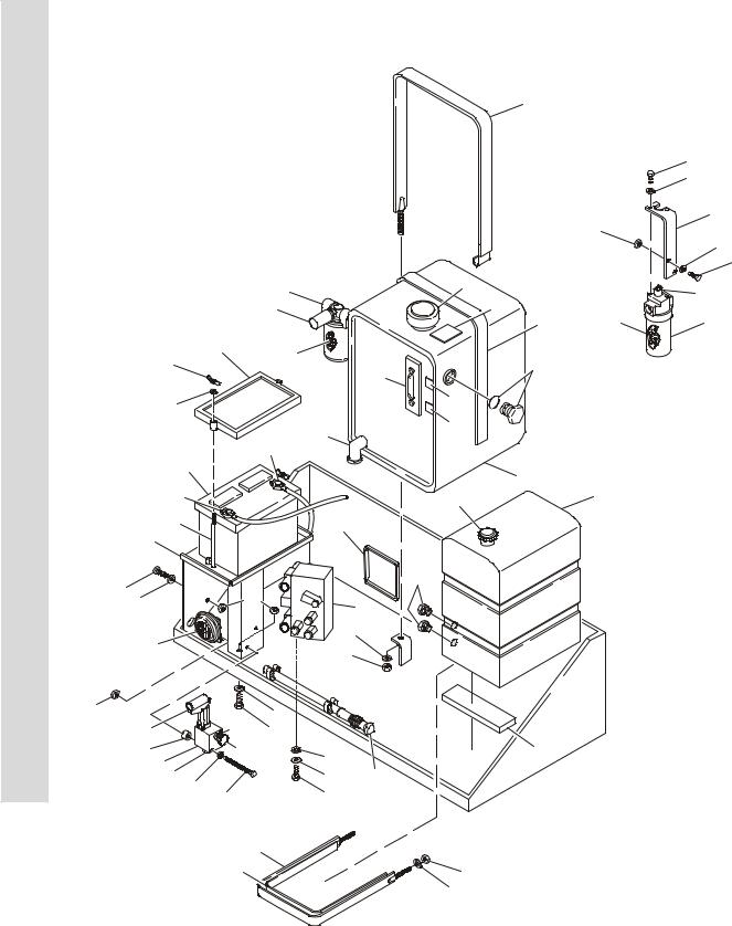
FIGURE 2-1. CONTROL VALVES & TANKS INSTALLATION
4
34
35
19
32
16
31
|
|
3 |
|
2B |
|
21B |
|
|
|
45 |
|
||
|
|
3B |
|
21A |
|
|
|
|
|
|
10 |
21 |
|
|
24 |
3A |
|
|
|
|
27 |
|
|
43 |
|
|
|
|
|
|
|
|
||
|
|
|
|
2A |
NOTE: LOCATED |
|
|
|
|
|
|
||
8 |
|
|
|
47 |
IN ENGINE TRAY |
|
|
|
|
|
|
||
|
|
|
|
|
|
|
|
|
|
2C |
48 |
|
|
|
|
41 |
|
|
|
|
25 |
|
|
|
|
|
|
|
|
|
|
|
|
|
23 |
|
|
|
2 |
|
|
|
|
|
|
|
|
|
42 |
|
|
|
1A |
1 |
|
|
|
|
|
|
|
|
26 |
|
|
44 |
|
|
|
|
|
|
|
|
|
|
20 |
|
|
|
|
|
|
31 |
|
|
|
46 |
|
|
32 |
|
|
|
|
||
16 |
|
18 |
|
|
||
|
|
|
|
|
|
|
38 |
|
|
8 |
|
|
|
39 |
|
|
|
|
|
|
|
|
|
|
|
|
|
40 |
|
|
7 |
|
|
|
35 |
|
|
|
|
|
|
32 |
|
16 |
|
|
|
|
22A |
22B |
|
|
|
|
|
31 |
|
|
|
|
||
37 |
22C |
|
17 |
11 |
|
|
22 |
|
|
16 |
|
|
|
22D |
|
|
28 |
|
|
|
50 |
|
|
|
|
|
|
33 |
|
15 |
29 |
|
|
|
|
|
|
|
|||
|
|
|
|
30 |
|
|
|
|
|
|
36 |
|
|
|
5 |
|
|
|
|
|
|
10 |
|
|
7 |
|
|
|
|
|
|
|
|
|
|
|
|
|
8 |
|
|
2-2 |
3120792 |

SECTION 2 GROUND COMPONENTS
.
FIGURE 2-1. CONTROL VALVES & TANKS INSTALLATION
FIG & ITEM # |
PART NUMBER |
DESCRIPTION |
QTY. |
REV. |
|
|
|
|
|
|
0256120 |
VALVES & TANKS INSTALLATION |
Ref. |
13 |
1 |
|
Tank, Fuel Options: |
1 |
|
|
4400371 |
Prior to S/N 37163 |
|
|
|
4400401 |
S/N 37163 to Present |
|
|
1A |
1120477 |
Cap, Fuel |
1 |
|
2 |
4400383 |
Hydraulic Tank Assembly |
1 |
|
2A |
7014802 |
Gauge, Sight |
1 |
|
2B |
7014803 |
Breather/Filler |
1 |
|
2C |
7026544 |
Elbow, W/Drain Plug |
1 |
|
3 |
2120157 |
Filter, Oil Return |
1 |
|
3A |
2120158 |
Element, Filter |
1 |
|
3B |
7016313 |
Switch, Pressure |
1 |
|
4 |
4240118 |
Strap, Hold-Down (Hydraulic Tank) |
1 |
|
5 |
4240117 |
Strap, Hold-Down (Fuel Tank) |
1 |
|
6 |
Not Used |
|
|
|
7 |
3311601 |
Nut 3/8”-16NC |
5 |
|
8 |
4751600 |
Flatwasher 3/8” |
7 |
|
9 |
0100011 |
Loctite #242 (Not Shown) |
A/R |
|
10 |
|
Molding Options: |
|
|
|
4280295 |
Strip, Bumper (Prior to S/N 37163) |
5ft/1.5m |
|
|
4420037 |
Molding, Rubber 1” (S/N 37163 to Present) |
7ft/2.1m |
|
11 |
4420038 |
Molding, Rubber 2” |
2ft/0.6m |
|
12 to 14 |
Not Used |
|
|
|
15 |
0641506 |
Bolt 5/16”-18NC x 3/4” |
3 |
|
16 |
4751500 |
Flatwasher 5/16” |
13 |
|
17 |
4761500 |
Lockwasher 5/16” |
3 |
|
18 |
4640977 |
Control Valve Assembly (See Figure 2-2 for Breakdown) |
1 |
|
19 |
0902289 |
Bracket, Mounting - Filter |
1 |
|
20 |
4845337 |
Bracket, Mounting - Battery |
1 |
|
21 |
2120146 |
Filter, Oil - Pressure |
1 |
|
21A |
2120150 |
Element, Filter |
1 |
|
21B |
7016312 |
Switch, Indicator |
1 |
|
22 |
4640859 |
Manual Descent Valve Assembly |
1 |
|
22A |
7012952 |
Cartridge, Pump |
1 |
|
22B |
7012954 |
Cartridge, Needle Valve |
1 |
|
|
7012953 |
Seal Kit - 7012954 Cartridge |
1 |
|
22C |
7012961 |
Knob |
1 |
|
22D |
7012955 |
Cartridge, Check |
1 |
|
|
7012940 |
Seal Kit - 7012955 Cartridge |
1 |
|
23 |
0400003 |
Battery |
1 |
|
24 |
0400002 |
Hold-Down, Battery |
1 |
|
24A |
2910479 |
Clips, Hold-Down (Not Shown) |
4 |
|
25 |
3980003 |
Seat, Battery |
1 |
|
26 |
0630370 |
Rod, Tie-Down |
2 |
|
27 |
3300029 |
Wingnut 3/8”-16NC |
2 |
|
28 |
2560123 |
Grip, Handle |
1 |
|
29 |
2560122 |
Handle, Manual Descent Valve |
1 |
|
|
|
|
|
|
S E C T I O N
2
G R O U N D
C O M P O N E N T S
3120792 |
2-3 |

S E C T I O N
2
G R O U N D
C O M P O N E N T S
SECTION 2 GROUND COMPONENTS
FIGURE 2-1. CONTROL VALVES & TANKS INSTALLATION (CONTINUED)
FIG & ITEM # |
PART NUMBER |
DESCRIPTION |
QTY. |
REV. |
|
|
|
|
|
30 |
1380136 |
Clip, Mounting |
2 |
|
31 |
0641508 |
Bolt 5/16”-18NC x 1” |
5 |
|
32 |
3311505 |
Locknut 5/16”-18NC |
7 |
|
33 |
0641530 |
Bolt 5/16”-18NC x 3 3/4” |
2 |
|
34 |
0651404 |
Bolt 1/4”-28NF x 1/2” |
2 |
|
35 |
4711400 |
Flatwasher 1/4” (Narrow) |
2 |
|
36 |
3820019 |
Rivet |
2 |
|
37 |
4566987 |
Tube, Spacer |
2 |
|
38 |
0140001 |
Horn |
1 |
|
39 |
0641406 |
Bolt 1/4”-20NC x 3/4” |
1 |
|
40 |
3311405 |
Locknut 1/4”-20NC |
1 |
|
41 |
1060360 |
Cable, Battery (Battery to Ground) |
1 |
|
42 |
1060632 |
Cable, Battery (Battery to Starter Relay) |
1 |
|
43 |
2220240 |
Plug, O-Ring |
2 |
|
44 |
4060807 |
Flex-Trim |
9ft/2.7m |
|
45 |
1701504 |
Decal - Hydraulic Fluid |
1 |
|
46 |
3300233 |
Plug, O-Ring |
2 |
|
47 |
1701502 |
Hydraulic Oil Level (High) |
1 |
|
48 |
1701503 |
Hydraulic Oil Level (Low) |
1 |
|
49 |
0100001 |
Adhesive (Not Shown) |
A/R |
|
50 |
4711500 |
Flatwasher (Narrow) (S/N 62148 to Present) |
4 |
|
|
|
|
|
|
2-4 |
3120792 |
Loading...