


 Loading...
User Service Guide
HP Integrity Superdome/sx2000 and HP 9000
Superdome/sx2000 Servers
HP Part Number: A9834-9001D_ed6
Published: September 2009
Edition: 6
Legal Notices
© Copyright 2009 Hewlett-Packard Development Company, L.P. The information contained herein is subject to change without notice.
The only warranties for HP products and services are set forth in the express warranty statements accompanying such products and services. Nothing herein should be construed as constituting an additional warranty. HP shall not be liable for technical or editorial errors or omissions contained herein.
Intel and Itanium are trademarks or registered trademarks of Intel Corporation or its subsidiaries in the United States and other countries.
Microsoft and Windows are U.S. registered trademarks of Microsoft Corporation.
UNIX is a registered trademark of The Open Group.

Table of Contents |
|
About This Document....................................................................................................... |
13 |
Intended Audience................................................................................................................................ |
13 |
Document Organization....................................................................................................................... |
13 |
Typographic Conventions..................................................................................................................... |
13 |
Related Information.............................................................................................................................. |
14 |
Publishing History................................................................................................................................ |
14 |
HP Encourages Your Comments.......................................................................................................... |
15 |
1 Overview....................................................................................................................... |
17 |
Server History and Specifications......................................................................................................... |
17 |
Server Components............................................................................................................................... |
18 |
Power Subsystem.................................................................................................................................. |
19 |
AC Power......................................................................................................................................... |
20 |
DC Power......................................................................................................................................... |
20 |
Power Sequencing............................................................................................................................ |
21 |
Enabling 48 Volts............................................................................................................................. |
21 |
Cooling System..................................................................................................................................... |
21 |
Utilities Subsystem................................................................................................................................ |
22 |
Platform Management..................................................................................................................... |
22 |
UGUY.............................................................................................................................................. |
23 |
CLU Functionality........................................................................................................................... |
23 |
PM3 Functionality........................................................................................................................... |
23 |
System Clocks.................................................................................................................................. |
24 |
Management Processor.................................................................................................................... |
24 |
Compact Flash................................................................................................................................. |
25 |
HUCB............................................................................................................................................... |
25 |
Backplane.............................................................................................................................................. |
26 |
Crossbar Chip.................................................................................................................................. |
26 |
Switch Fabrics.................................................................................................................................. |
27 |
Backplane Monitor and Control...................................................................................................... |
27 |
I2C Bus Distribution........................................................................................................................ |
27 |
Clock Subsystem.............................................................................................................................. |
27 |
System Clock Distribution......................................................................................................... |
27 |
Hot-Swap Oscillator................................................................................................................... |
28 |
sx2000 RCS Module.................................................................................................................... |
28 |
Cabinet ID........................................................................................................................................ |
29 |
Cell ID.............................................................................................................................................. |
29 |
Backplane Power Requirements and Power Distribution............................................................... |
29 |
CPUs and Memories............................................................................................................................. |
30 |
Cell Controller................................................................................................................................. |
31 |
Processor Interface........................................................................................................................... |
31 |
Processors........................................................................................................................................ |
32 |
Cell Memory System....................................................................................................................... |
32 |
Memory Controller .................................................................................................................... |
33 |
DIMM Architecture.................................................................................................................... |
33 |
Memory Interconnect................................................................................................................. |
33 |
Mixing Different Sized DIMMs.................................................................................................. |
34 |
Memory Interleaving................................................................................................................. |
34 |
Memory Bank Attribute Table.............................................................................................. |
34 |
Cell Map................................................................................................................................ |
35 |
Table of Contents |
3 |
Link Interleaving................................................................................................................... |
35 |
Memory Error Protection........................................................................................................... |
35 |
DRAM Erasure........................................................................................................................... |
36 |
PDC Functional Changes................................................................................................................. |
36 |
Platform Dependent Hardware....................................................................................................... |
36 |
Reset................................................................................................................................................. |
37 |
Cell OL*........................................................................................................................................... |
37 |
I/O Subsystem....................................................................................................................................... |
37 |
PCI-X Backplane Functionality........................................................................................................ |
38 |
SBA Chip CC-to-Ropes.............................................................................................................. |
38 |
Ropes-to-PCI LBA Chip............................................................................................................. |
39 |
PCI Slots..................................................................................................................................... |
40 |
Mixed PCI-X and PCI Express I/O Chassis........................................................................... |
40 |
PCI Hot-Swap Support......................................................................................................... |
41 |
System Management Station................................................................................................................ |
41 |
User Accounts.................................................................................................................................. |
42 |
New Server Cabling.............................................................................................................................. |
42 |
m-Link Cable................................................................................................................................... |
42 |
e-Link Cable..................................................................................................................................... |
42 |
Clock Cable...................................................................................................................................... |
44 |
Firmware............................................................................................................................................... |
44 |
Itanium Firmware for HP Integrity Superdome/sx2000................................................................. |
44 |
Itanium System Firmware Functions......................................................................................... |
46 |
PA-RISC Firmware for HP 9000/sx2000 Servers.............................................................................. |
46 |
PA-RISC System Firmware Functions........................................................................................ |
47 |
Server Configurations........................................................................................................................... |
47 |
Server Errors......................................................................................................................................... |
48 |
2 System Specifications................................................................................................... |
49 |
Dimensions and Weights...................................................................................................................... |
49 |
Component Dimensions.................................................................................................................. |
49 |
Component Weights........................................................................................................................ |
49 |
Shipping Dimensions and Weights................................................................................................. |
50 |
Electrical Specifications......................................................................................................................... |
50 |
Grounding....................................................................................................................................... |
51 |
Circuit Breaker................................................................................................................................. |
51 |
Power Options................................................................................................................................. |
51 |
System Power Requirements........................................................................................................... |
52 |
Component Power Requirements................................................................................................... |
53 |
IOX Cabinet Power Requirements................................................................................................... |
53 |
IOX Cabinet Power Cords............................................................................................................... |
53 |
Environmental Requirements............................................................................................................... |
54 |
Temperature and Humidity Specifications..................................................................................... |
54 |
Power Dissipation............................................................................................................................ |
54 |
Acoustic Noise Specification........................................................................................................... |
56 |
Airflow............................................................................................................................................. |
56 |
3 Installing the System..................................................................................................... |
59 |
Introduction ......................................................................................................................................... |
59 |
Communications Interference ........................................................................................................ |
59 |
Electrostatic Discharge ................................................................................................................... |
59 |
Public Telecommunications Network Connection.......................................................................... |
60 |
Unpacking and Inspecting the System................................................................................................. |
60 |
4Table of Contents
Verifying Site Preparation............................................................................................................... |
60 |
Gathering LAN Information...................................................................................................... |
60 |
Verifying Electrical Requirements.............................................................................................. |
60 |
Checking the Inventory................................................................................................................... |
60 |
Inspecting the Shipping Containers for Damage............................................................................ |
61 |
Inspection Precautions............................................................................................................... |
62 |
Claims Procedures ..................................................................................................................... |
62 |
Unpacking and Inspecting Hardware Components....................................................................... |
62 |
Tools Required............................................................................................................................ |
63 |
Unpacking the Cabinet............................................................................................................... |
63 |
Unpacking the PDCA...................................................................................................................... |
71 |
Returning Equipment...................................................................................................................... |
71 |
Setting Up the System........................................................................................................................... |
72 |
Moving the System and Related Equipment to the Installation Site .............................................. |
72 |
Unpacking and Installing the Blower Housings and Blowers........................................................ |
72 |
Attaching the Side Skins and Blower Side Bezels........................................................................... |
75 |
Attaching the Side Skins............................................................................................................ |
75 |
Attaching the Blower Side Bezels............................................................................................... |
77 |
Attaching the Leveling Feet and Leveling the Cabinet................................................................... |
79 |
Installing the Front Door Bezels and the Front and Rear Blower Bezels ....................................... |
79 |
Installing the Front Door Bezels................................................................................................. |
79 |
Installing the Rear Blower Bezel................................................................................................ |
81 |
Installing the Front Blower Bezel............................................................................................... |
82 |
Wiring Check................................................................................................................................... |
83 |
Installing and Verifying the PDCA................................................................................................. |
84 |
Checking Voltage............................................................................................................................. |
88 |
Removing the EMI Panels............................................................................................................... |
89 |
Connecting the Cables..................................................................................................................... |
91 |
Routing the I/O Cables.................................................................................................................... |
91 |
Installing the Support Management Station......................................................................................... |
93 |
Installing the SMS Support Shelf.......................................................................................................... |
93 |
Connecting the SMS to the Superdome................................................................................................ |
94 |
SMS Software and Superdome Firmware Downloading Procedure.................................................... |
94 |
Configuring the Event Information Tools............................................................................................. |
95 |
Turning On Housekeeping Power........................................................................................................ |
96 |
Connecting the MP to the Customer LAN........................................................................................... |
98 |
Connecting the MP to the Network................................................................................................. |
98 |
Setting the Customer IP Address.................................................................................................... |
99 |
Booting and Verifying the System...................................................................................................... |
101 |
Connecting to the MP.................................................................................................................... |
101 |
Powering On the System 48 V Power Supply................................................................................ |
104 |
Booting the HP Integrity Superdome/sx2000 to an EFI Shell........................................................ |
104 |
Booting an HP 9000 sx2000 Server to BCH.................................................................................... |
106 |
Verifying the System...................................................................................................................... |
106 |
Running JET Software......................................................................................................................... |
108 |
Running JUST ............................................................................................................................... |
108 |
Power Cycling After Using JET..................................................................................................... |
109 |
Offline Diagnostic Environment......................................................................................................... |
109 |
Attaching the Rear Kick Plates............................................................................................................ |
109 |
Performing a Visual Inspection and Completing the Installation...................................................... |
110 |
Conducting a Post-Installation Check................................................................................................. |
112 |
4 Booting and Shutting Down the Operating System............................................... |
113 |
Operating Systems Supported on Cell-based HP Servers.................................................................. |
113 |
Table of Contents |
5 |
System Boot Configuration Options................................................................................................... |
114 |
HP 9000 Boot Configuration Options............................................................................................ |
114 |
HP Integrity Boot Configuration Options..................................................................................... |
114 |
Booting and Shutting Down HP-UX................................................................................................... |
118 |
HP-UX Support for Cell Local Memory........................................................................................ |
118 |
Adding HP-UX to the Boot Options List....................................................................................... |
118 |
Booting HP-UX.............................................................................................................................. |
119 |
Standard HP-UX Booting......................................................................................................... |
120 |
Single-User Mode HP-UX Booting........................................................................................... |
123 |
LVM-Maintenance Mode HP-UX Booting............................................................................... |
126 |
Shutting Down HP-UX.................................................................................................................. |
127 |
Booting and Shutting Down HP OpenVMS I64................................................................................. |
128 |
HP OpenVMS I64 Support for Cell Local Memory....................................................................... |
129 |
Adding HP OpenVMS to the Boot Options List............................................................................ |
129 |
Booting HP OpenVMS................................................................................................................... |
131 |
Shutting Down HP OpenVMS....................................................................................................... |
132 |
Booting and Shutting Down Microsoft Windows.............................................................................. |
133 |
Microsoft Windows Support for Cell Local Memory.................................................................... |
133 |
Adding Microsoft Windows to the Boot Options List................................................................... |
134 |
Booting Microsoft Windows.......................................................................................................... |
135 |
Shutting Down Microsoft Windows.............................................................................................. |
137 |
Booting and Shutting Down Linux..................................................................................................... |
138 |
Linux Support for Cell Local Memory.......................................................................................... |
138 |
Adding Linux to the Boot Options List......................................................................................... |
139 |
Booting Red Hat Enterprise Linux................................................................................................ |
140 |
Booting SuSE Linux Enterprise Server ......................................................................................... |
141 |
Shutting Down Linux.................................................................................................................... |
142 |
A sx2000 LEDs.............................................................................................................. |
145 |
B Management Processor Commands........................................................................ |
149 |
BO Command ..................................................................................................................................... |
149 |
CA Command..................................................................................................................................... |
149 |
CC Command...................................................................................................................................... |
150 |
CP Command...................................................................................................................................... |
151 |
DATE Command................................................................................................................................. |
152 |
DC Command..................................................................................................................................... |
152 |
DF Command...................................................................................................................................... |
153 |
DI Command....................................................................................................................................... |
154 |
DL Command...................................................................................................................................... |
155 |
EL Command...................................................................................................................................... |
155 |
HE Command..................................................................................................................................... |
156 |
ID Command....................................................................................................................................... |
157 |
IO Command....................................................................................................................................... |
158 |
IT Command....................................................................................................................................... |
159 |
LC Command...................................................................................................................................... |
159 |
LS Command....................................................................................................................................... |
160 |
MA Command.................................................................................................................................... |
160 |
ND Command..................................................................................................................................... |
161 |
PD Command...................................................................................................................................... |
161 |
PE Command...................................................................................................................................... |
162 |
PS Command....................................................................................................................................... |
163 |
RE Command...................................................................................................................................... |
164 |
6Table of Contents
RL Command...................................................................................................................................... |
165 |
RR Command...................................................................................................................................... |
166 |
RS Command...................................................................................................................................... |
166 |
SA Command...................................................................................................................................... |
167 |
SO Command...................................................................................................................................... |
167 |
SYSREV Command............................................................................................................................. |
168 |
TC Command...................................................................................................................................... |
169 |
TE Command...................................................................................................................................... |
169 |
VM Command..................................................................................................................................... |
170 |
WHO Command................................................................................................................................. |
170 |
XD Command..................................................................................................................................... |
171 |
C Powering the System On and Off ........................................................................... |
173 |
Shutting Down the System................................................................................................................. |
173 |
Checking System Configuration.................................................................................................... |
173 |
Shutting Down the Operating System........................................................................................... |
175 |
Preparing the Partitions for Shutdown.......................................................................................... |
176 |
Powering Off the System............................................................................................................... |
177 |
Turning On Housekeeping Power...................................................................................................... |
178 |
Powering On the System Using the PE Command............................................................................. |
180 |
D Templates.................................................................................................................... |
183 |
Templates............................................................................................................................................ |
183 |
Equipment Footprint Templates.................................................................................................... |
185 |
Computer Room Layout Plan........................................................................................................ |
185 |
Index............................................................................................................................... |
197 |
Table of Contents |
7 |

List of Figures
1-1 |
Superdome History....................................................................................................................... |
17 |
1-2 |
Superdome Cabinet Components................................................................................................. |
19 |
1-3 |
UGUY............................................................................................................................................ |
23 |
1-4 |
Management Processor................................................................................................................. |
25 |
1-5 |
HUCB............................................................................................................................................. |
26 |
1-6 |
HSO and RCS Locations................................................................................................................ |
29 |
1-7 |
Backplane Power Supply Module................................................................................................. |
30 |
1-8 |
Backplane (Rear View).................................................................................................................. |
30 |
1-9 |
Cell Board...................................................................................................................................... |
31 |
1-10 |
Cell Memory.................................................................................................................................. |
33 |
1-11 |
PCI-X I/O Rope Mapping.............................................................................................................. |
39 |
1-12 |
PCIe I/O Rope Mapping................................................................................................................ |
41 |
1-13 |
e-Link Cable................................................................................................................................... |
43 |
1-14 |
Backplane Cables........................................................................................................................... |
44 |
1-15 |
Itanium Firmware Interfaces......................................................................................................... |
45 |
1-16 |
PA-RISC Firmware Interfaces........................................................................................................ |
47 |
2-1 |
PDCA Locations............................................................................................................................ |
52 |
2-2 |
Airflow Diagram........................................................................................................................... |
57 |
3-1 |
Normal Tilt Indicator.................................................................................................................... |
61 |
3-2 |
Abnormal Tilt Indicator ................................................................................................................ |
62 |
3-3 |
Front of Cabinet Container............................................................................................................ |
64 |
3-4 |
Cutting the Polystrap Bands.......................................................................................................... |
64 |
3-5 |
Removing the Ramps from the Pallet............................................................................................ |
65 |
3-6 |
Power Supply Mounting Screws Location.................................................................................... |
66 |
3-7 |
I/O Chassis Mounting Screws....................................................................................................... |
66 |
3-8 |
Shipping Strap Location................................................................................................................ |
68 |
3-9 |
Removing the Mounting Brackets................................................................................................. |
69 |
3-10 |
Positioning the Ramps................................................................................................................... |
70 |
3-11 |
Rolling the Cabinet Down the Ramp............................................................................................ |
70 |
3-12 |
Blower Housing Frame.................................................................................................................. |
72 |
3-13 |
Removing Protective Cardboard from the Housing..................................................................... |
73 |
3-14 |
Installing the Rear Blower Housing.............................................................................................. |
73 |
3-15 |
Installing the Front Blower Housing............................................................................................. |
74 |
3-16 |
Installing the Blowers.................................................................................................................... |
75 |
3-17 |
Attaching the Rear Side Skin......................................................................................................... |
76 |
3-18 |
Attaching the Front Side Skins...................................................................................................... |
77 |
3-19 |
Attaching the Side Bezels.............................................................................................................. |
78 |
3-20 |
Attaching the Leveling Feet........................................................................................................... |
79 |
3-21 |
Installing the Lower Front Door Assembly................................................................................... |
80 |
3-22 |
Installing the Upper Front Door Assembly................................................................................... |
81 |
3-23 |
Installing the Rear Blower Bezel.................................................................................................... |
82 |
3-24 |
Installing the Front Blower Bezel.................................................................................................. |
83 |
3-25 |
PDCA Assembly for Options 6 and 7............................................................................................ |
85 |
3-26 |
A 4-Wire Connector....................................................................................................................... |
85 |
3-27 |
A 5-Wire Connector....................................................................................................................... |
86 |
3-28 |
Installing the PDCA....................................................................................................................... |
86 |
3-29 |
Checking PDCA Test Points (5-Wire)............................................................................................ |
87 |
3-30 |
Wall Receptacle Pinouts................................................................................................................ |
88 |
3-31 |
Power Supply Indicator LED........................................................................................................ |
89 |
3-32 |
Removing Front EMI Panel Screw................................................................................................ |
90 |
3-33 |
Removing the Back EMI Panel...................................................................................................... |
90 |
3-34 |
Cable Labeling............................................................................................................................... |
91 |
8List of Figures
3-35 |
Routing I/O Cables........................................................................................................................ |
92 |
3-36 |
Front Panel with HKP and Present LEDs...................................................................................... |
97 |
3-37 |
BPS LEDs....................................................................................................................................... |
98 |
3-38 |
MP LAN Connection Location...................................................................................................... |
99 |
3-39 |
LAN Configuration Screen.......................................................................................................... |
100 |
3-40 |
The ls Command Screen.............................................................................................................. |
101 |
3-41 |
Logging In.................................................................................................................................... |
102 |
3-42 |
Main MP Menu............................................................................................................................ |
102 |
3-43 |
MP Command Option................................................................................................................. |
103 |
3-44 |
MP Virtual Front Panel................................................................................................................ |
103 |
3-45 |
Example of Partition State—Cabinet Not Powered Up............................................................... |
103 |
3-46 |
MP Console Option..................................................................................................................... |
104 |
3-47 |
HP Integrity Superdome/sx2000 EFI Boot Manager................................................................... |
105 |
3-48 |
EFI Shell Prompt.......................................................................................................................... |
105 |
3-49 |
HP Integrity Superdome/sx2000 Partitions at System Firmware Console.................................. |
106 |
3-50 |
Power Status First Window......................................................................................................... |
107 |
3-51 |
Power Status Window................................................................................................................. |
107 |
3-52 |
Power Status Showing State of UGUY LEDs .............................................................................. |
108 |
3-53 |
Attaching Rear Kick Plates.......................................................................................................... |
110 |
3-54 |
Cell Board Ejectors....................................................................................................................... |
111 |
3-55 |
Front EMI Panel Flange and Cabinet Holes................................................................................ |
111 |
3-56 |
Reinstalling the Back EMI Panel.................................................................................................. |
112 |
A-1 |
Utilities ........................................................................................................................................ |
147 |
A-2 |
PDH Status.................................................................................................................................. |
147 |
C-1 |
Connecting to the Host................................................................................................................ |
173 |
C-2 |
Main MP Menu............................................................................................................................ |
173 |
C-3 |
Checking for Other Users............................................................................................................ |
174 |
C-4 |
Checking Current System Configuration.................................................................................... |
174 |
C-5 |
MP Virtual Front Panel................................................................................................................ |
174 |
C-6 |
Example of Partition State........................................................................................................... |
175 |
C-7 |
Partition Consoles Menu............................................................................................................. |
175 |
C-8 |
Entering the rr Command........................................................................................................... |
176 |
C-9 |
Using the de -s Command........................................................................................................ |
177 |
C-10 |
Power Entity Command.............................................................................................................. |
177 |
C-11 |
Power Status First Window......................................................................................................... |
178 |
C-12 |
Power Status Second Window..................................................................................................... |
178 |
C-13 |
Front Panel Display with Housekeeping (HKP) Power and Present LEDs On.......................... |
179 |
C-14 |
BPS LEDs..................................................................................................................................... |
180 |
C-15 |
Power Entity Command.............................................................................................................. |
181 |
C-16 |
Power Status First Window......................................................................................................... |
181 |
C-17 |
Power Status Window................................................................................................................. |
182 |
D-1 |
Cable Cutouts and Caster Locations........................................................................................... |
183 |
D-2 |
SD16 and SD32 Space Requirements........................................................................................... |
184 |
D-3 |
SD64 Space Requirements........................................................................................................... |
185 |
D-4 |
Computer Floor Template........................................................................................................... |
186 |
D-5 |
Computer Floor Template........................................................................................................... |
187 |
D-6 |
Computer Floor Template........................................................................................................... |
188 |
D-7 |
Computer Floor Template........................................................................................................... |
189 |
D-8 |
Computer Floor Template........................................................................................................... |
190 |
D-9 |
SD32, SD64, and IOX Cabinet Templates.................................................................................... |
191 |
D-10 |
SD32, SD64, and IOX Cabinet Templates.................................................................................... |
192 |
D-11 |
SD32, SD64, and IOX Cabinet Templates.................................................................................... |
193 |
D-12 |
SD32, SD64, and IOX Cabinet Templates.................................................................................... |
194 |
D-13 |
SD32, SD64, and IOX Cabinet Templates.................................................................................... |
195 |
D-14 |
SD32, SD64, and IOX Cabinet Templates.................................................................................... |
196 |
9

List of Tables
1-1 |
HSO LED Status Indicator Meaning............................................................................................. |
28 |
1-2 |
Supported Processors and Minimum Firmware Versions............................................................ |
32 |
1-3 |
SMS Lifecycles............................................................................................................................... |
42 |
2-1 |
Server Component Dimensions.................................................................................................... |
49 |
2-2 |
I/O Expansion Cabinet Component Dimensions.......................................................................... |
49 |
2-3 |
System Component Weights......................................................................................................... |
49 |
2-4 |
IOX Cabinet Weights..................................................................................................................... |
50 |
2-5 |
Miscellaneous Dimensions and Weights....................................................................................... |
50 |
2-6 |
Available Power Options............................................................................................................... |
51 |
2-7 |
Option 6 and 7 Specifics................................................................................................................ |
51 |
2-8 |
Power Requirements (Without SMS)............................................................................................ |
52 |
2-9 |
Component Power Requirements (Without SMS)........................................................................ |
53 |
2-10 |
I/O Expansion Cabinet Power Requirements (Without SMS)....................................................... |
53 |
2-11 |
I/O Expansion Cabinet Component Power Requirements............................................................ |
53 |
2-12 |
I/O Expansion Cabinet ac Power Cords........................................................................................ |
54 |
2-13 |
Operational Physical Environment Requirements........................................................................ |
54 |
2-14 |
Nonoperational Physical Environment Requirements................................................................. |
54 |
2-15 |
HP Integrity Superdome/sx2000 Dual-Core CPU Configurations............................................... |
55 |
2-16 |
HP Integrity Superdome/sx2000 Single-Core CPU Configurations............................................. |
55 |
2-17 |
Physical Environmental Specifications......................................................................................... |
57 |
3-1 |
Available Power Options............................................................................................................... |
71 |
3-2 |
Power Cord Option 6 and 7 Details............................................................................................... |
71 |
3-3 |
4- and 5-Wire Voltage Ranges....................................................................................................... |
87 |
A-1 |
Front Panel LEDs......................................................................................................................... |
145 |
A-2 |
Power and OL* LEDs................................................................................................................... |
146 |
A-3 |
OL* LED States............................................................................................................................ |
147 |
A-4 |
PDH Status and Power Good LED States.................................................................................... |
148 |
10 List of Tables
List of Examples
3-1 |
Directory Example......................................................................................................................... |
95 |
3-2 |
Directory Example......................................................................................................................... |
95 |
4-1 |
Single-User HP-UX Boot.............................................................................................................. |
124 |
B-1 |
BO command............................................................................................................................... |
149 |
B-2 |
CA Command.............................................................................................................................. |
150 |
B-3 |
CC Command.............................................................................................................................. |
151 |
B-4 |
CP Command.............................................................................................................................. |
152 |
B-5 |
DATE Command......................................................................................................................... |
152 |
B-6 |
DC Command.............................................................................................................................. |
153 |
B-7 |
DF Command.............................................................................................................................. |
154 |
B-8 |
DI Command............................................................................................................................... |
155 |
B-9 |
DL Command.............................................................................................................................. |
155 |
B-10 |
EL Command............................................................................................................................... |
156 |
B-11 |
HE Command.............................................................................................................................. |
157 |
B-12 |
ID Command............................................................................................................................... |
158 |
B-13 |
Example: ..................................................................................................................................... |
159 |
B-14 |
IT Command................................................................................................................................ |
159 |
B-15 |
LC Command.............................................................................................................................. |
160 |
B-16 |
LS Command............................................................................................................................... |
160 |
B-17 |
MP Main Menu............................................................................................................................ |
161 |
B-18 |
ND Command............................................................................................................................. |
161 |
B-19 |
PD Command.............................................................................................................................. |
162 |
B-20 |
PE Command for a Compute Cabinet......................................................................................... |
163 |
B-21 |
PS Command............................................................................................................................... |
164 |
B-22 |
Re-key lock for partition 3........................................................................................................... |
166 |
B-23 |
RR Command.............................................................................................................................. |
166 |
B-24 |
RS Command............................................................................................................................... |
167 |
B-25 |
SA Command.............................................................................................................................. |
167 |
B-26 |
SO Command.............................................................................................................................. |
168 |
B-27 |
SYSREV Command...................................................................................................................... |
169 |
B-28 |
TC Command.............................................................................................................................. |
169 |
B-29 |
TE Command............................................................................................................................... |
170 |
B-30 |
VM Command............................................................................................................................. |
170 |
B-31 |
WHO Command.......................................................................................................................... |
171 |
B-32 |
XD Command.............................................................................................................................. |
172 |
11
12

About This Document
Thisdocumentcontainsthesystemoverview,system-specificparameters,installationprocedures of the system, operating system specifics, and procedures for components in the system.
Intended Audience
This document is intended for HP trained Customer Support Consultants.
Document Organization
This document is organized as follows:
Chapter 1 This chapter presents an historical view of the Superdome server family, describes the various server components, and describes how the server components function together.
Chapter 2 This chapter contains the dimensions and weights for the server and various components.Electricalspecifications,environmentalrequirements,andtemplates are also included.
Chapter 3 Thischapterdescribeshowtounpackandinspectthesystem,setupthesystem, connect the MP to the customer LAN, and how to complete the installation.
Chapter 4 Thischapterdescribeshowtobootandshutdowntheserveroperatingsystem
(OS) for each OS supported.
Appendix A ThisappendixcontainstablesthatdescribethevariousLEDstatesforthefront panel, power and OL* states, and OL* states for I/O chassis cards.
Appendix B This appendix provides a summary for each management processor (MP) command. Screen output is provided for each command so you can see the results of the command.
Appendix C Thisappendixprovidesprocedurestopoweroffandpoweronthesystemwhen the removal and replacement of a component requires it.
Appendix D This appendix contains templates for cable cutouts and caster locations; SD16, SD32, SD64, and I/O expansion cabinets; and the computer room floor.
Typographic Conventions
The following typographic conventions are used in this document.
 WARNING! Lists requirements that you must meet to avoid personal injury.
CAUTION: Provides information required to avoid losing data or to avoid losing system functionality.
 IMPORTANT: Provides essential information to explain a concept or to complete a task.
NOTE: Highlights useful information such as restrictions, recommendations, or important details about HP product features.
• Commands and options are represented using this font.
•Text that you type exactly as shown is represented using this font.
Intended Audience |
13 |

•Text to be replaced with text that you supply is represented using this font.
Example:“Enterthels -l filenamecommand”meansyoumustreplacefilenamewithyour own text.
•Keyboard keys and graphical interface items (such as buttons, tabs, and menu items) are represented using this font.
Examples: The Control key, the OK button, the General tab, the Options menu.
•Menu —> Submenu represents a menu selection you can perform.
Example: “Select the Partition —> Create Partition action” means you must select the
Create Partition menu item from the Partition menu.
•Example screen output is represented using this font.
Related Information
FurtherinformationonHPserverhardwaremanagement,Microsoft®Windows®,anddiagnostic support tools are available through the following website links.
WebsiteforHPTechnicalDocumentation ThefollowinglinkisthemainwebsiteforHPtechnical documentation.ThissiteofferscomprehensiveinformationaboutHPproductsavailableforfree. See http://docs.hp.com.
Server Hardware Information The following link is the systems hardware section of the docs.hp.com website. It provides HP nPartition server hardware management information, includinginformationonsitepreparation,installation,andsoon. See http://docs.hp.com/hpux/ hw/.
Diagnostics and Event Monitoring: Hardware Support Tools The following link contains comprehensive information about HP hardware support tools, including online and offline diagnostics and event monitoring tools. This website has manuals, tutorials, FAQs, and other reference material. See http://docs.hp.com/hpux/diag.
Website for HP Technical Support The following link is the HP IT resource center website and provides comprehensive support information for IT professionals on a wide variety of topics, including software, hardware, and networking. See http://us-sup port2.external.hp.com.
Publishing History
The document printing date and edition number indicate the document’s current edition and areincludedinthefollowingtable.Theprintingdatewillchangewhenaneweditionisproduced. Documentupdatesmaybeissuedbetweeneditionstocorrecterrorsordocumentproductchanges. The latest version of this document is available on line at:
docs.hp.com.
First Edition . . . . . . . . . . . . . . . . . . . . . . . . . . . . . . . . . . . . . . . . . . . . . . . . . . . . . . . . |
March 2006 |
Second Edition . . . . . . . . . . . . . . . . . . . . . . . . . . . . . . . . . . . . . . . . . . . . . . . . . . . . . . . . |
September 2006 |
Third Edition . . . . . . . . . . . . . . . . . . . . . . . . . . . . . . . . . . . . . . . . . . . . . . . . . . . . . . . . |
February 2007 |
Fourth Edition . . . . . . . . . . . . . . . . . . . . . . . . . . . . . . . . . . . . . . . . . . . . . . . . . . . . . . . . |
November 2007 |
Fifth Edition . . . . . . . . . . . . . . . . . . . . . . . . . . . . . . . . . . . . . . . . . . . . . . . . . . . . . . . . |
March 2009 |
Sixth Edition . . . . . . . . . . . . . . . . . . . . . . . . . . . . . . . . . . . . . . . . . . . . . . . . . . . . . . . . |
September 2009 |
14

HP Encourages Your Comments
HP welcomes your feedback on this publication. Direct your comments to http://docs.hp.com/ en/feedback.html and note that you will not receive an immediate reply. All comments are appreciated.
HP Encourages Your Comments 15
16
1 Overview
Server History and Specifications
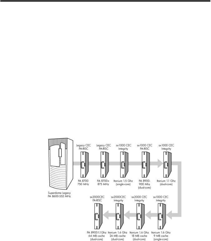
Superdome was introduced as the new platform architecture for high-end HP servers between the years 2000 and 2004. Superdome represented the first collaborative hardware design effort between traditional HP and Convex technologies. Superdome was designed to replace T- and
V-Class servers and to prepare for the transition from PA-RISC to Intel® Itanium® processors. The new design enabled the ability of running different operating systems on the same server. Thedesignalsoincludedseveralnew,high-availabilityfeatures.Initially,Superdomewasreleased with the legacy core electronics complex (CEC) and a 552 MHz PA-8600 processor. The Legacy CEC supported two additional speeds; a 750 MHz PA-8700 followed by an 875 MHz PA-8700 processor.
The HP Integrity server project consisted of four projects based on the sx1000 CEC chipset and the Integrity cell boards. The first release was the sx1000 chipset, Integrity cell boards, Itanium
firmware and a 1.2 MHz Intel® processor. This release included PCI-X and PCI I/O mixes. The Integrity systems were compatible with the legacy Superdome IOX.
The second release, based on the sx1000 CEC, included Integrity cell boards, but used PA-RISC firmware, and a dual-core PA-RISC processor. The release also included a 2 GB DIMM and a newHP-UXversion.Componentssuchasprocessors,processorpowerpods,memory,firmware, and operating system all changed for this release.
Figure 1-1 Superdome History
The third release, also based on the sx1000 chipset, included the Integrity cell boards, Itanium firmware,anda1.5MHzItaniumCPU.TheCPUmoduleconsistedofadual-coreprocessorwith a new cache controller. The firmware allowed for mixed cells within a system. All three DIMM sizes were supported. Firmware and operating system changes were minor compared to their earlier versions.
ThefourthandfinalreleaseistheHPsuperscalablesx2000processorchipset. Itisalsobasedon the new CEC that supports up to 128 PA-RISC or Itanium processors. It is the last generation of Superdome servers to support the PA-RISC family of processors. Modifications to the server components include:
Server History and Specifications |
17 |
•the new CEC chipset
•board changes including cell board
•system backplane
•I/O backplane
•associated power boards
•interconnect
•a redundant, hot-swappable clock source
Server Components
A Superdome system consists of the following types of cabinet assemblies:
•MinimumofoneSuperdomeleft-sidecabinet.TheSuperdomecabinetcontainstheprocessors, the memory, and the core devices of the system. They also house the system's PCI cards. Systemscanincludebothleftandrightcabinetassembliescontainingaleftorrightbackplane (SD64) respectively.
•One or more HP Rack System/E cabinets. These rack cabinets are used to hold the system peripheral devices such as disk drives.
•Optionally, one or more I/O expansion cabinets (Rack System/E). An I/O expansion cabinet is required when a customer requires more PCI cards than can be accommodated in the Superdome cabinets.
The width of the cabinet assemblies accommodates moving them through standard-sized doorways. The intake air to the main (cell) card cage is filtered. This air filter is removable for cleaning and replacement while the system is fully operational.
Astatusdisplayislocatedontheoutsideofthefrontandreardoorsofeachcabinet.Thisfeature enables you to determine the basic status of each cabinet without opening any cabinet doors.
The Superdome is a cell-based system. Cells communicate with others utilizing the crossbar on the backplane. Every cell has its own I/O interface, which can be connected to one 12-slot I/O card cage using two System Bus Adapter (SBA) link cables. Not all SBA links are connected by default, due to a physical limitation of four I/O card cages per cabinet or node. In addition to these components, each system consists of a power subsystem and a utility subsystem. Three types of Superdome are available:
•SD16
•SD32
•SD64, a two-cabinet system with single-CPU cell board sockets
The SD## represents the maximum number of available CPU sockets.
An SD16 contains the following components:
•Up to four cell boards
•Four I/O card cages
•Five I/O fans
•Four system cooling fans
•Four bulk power supplies (BPS)
•Two power distribution control assemblies (PDCA)
TwobackplaneN+1powersuppliesprovidepowertotheSD16.Thefourcellboardsareconnected to one pair of crossbar chips (XBC). The backplane of an SD16 is the same as a backplane of an SD32. On the HUCB utility PCB is a switch set to TYPE= 1.
An SD32 has up to eight cell boards. All eight cell boards are connected to two pairs of XBCs. TheSD32backplaneisdesignedforasystemupgradetoanSD64. OnanSD32,fouroftheeight connectorsuseU-Turncables.TheU-Turncablesdoublethenumberoflinksandthebandwidth betweentheXBCsandarerecommendedtoachievebestperformance.AnSD64hasupto16cell boards and requires two cabinets. All 16 cell boards are connected to four pairs of XBCs. The
18 Overview
SD64 consists of left backplane and right backplane cabinets, which are connected using 12 m-Link cables.
When the PA-RISC dual-core or the Itanium dual-core processors are used, the CPU counts are
doubledbytheuseofthedual-dieprocessors,assupportedontheIntel® Itanium® cellboards. Up to 128 processors can be supported.
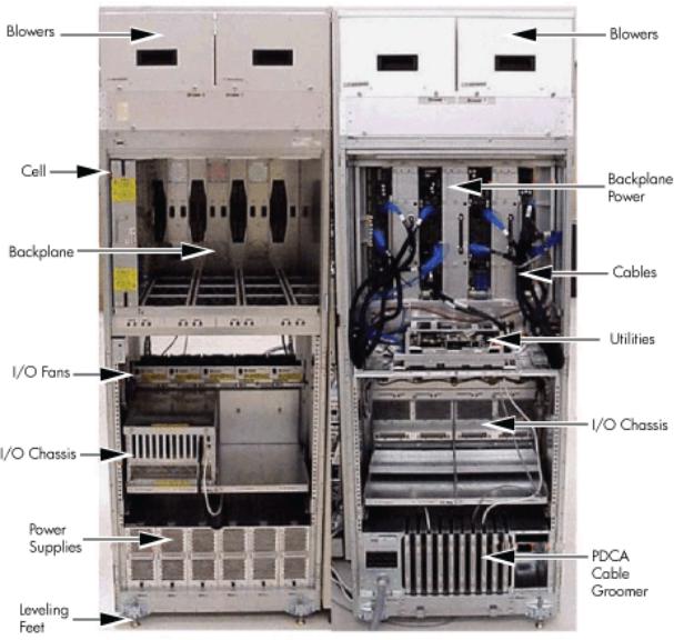
Figure 1-2 Superdome Cabinet Components
Power Subsystem
The power subsystem consists of the following components:
•One or two PDCAs
•One Front End Power Supply (FEPS)
•Up to six BPS
•One power board per cell
•An HIOB power system
•Backplane power bricks
•Power monitor (PM) on the Universal Glob of Utilities (UGUY)
•Local power monitors (LPM) on the cell, the HIOB, and the backplanes
Power Subsystem 19
AC Power
The ac power system includes the PDCA, one FEPS, and up to six BPS.
The FEPS is a modular, 2n+2 shelf assembly power system that can consume up to 17 KVA of power from ac sources. The purpose of the FEPS chassis is to provide interconnect, signal and voltage busing between the PDCAs and BPSs, between the BPSs and utility subsystem, and betweentheBPSandthesystempowerarchitecture.TheFEPSsubsystemcomprisesthreedistinct modular assemblies: six BPS, two PDCAs, and one FEPS chassis.
At least one 3-phase PDCA per Superdome cabinet is required. For redundancy, you can use a second PDCA. The purpose of the PDCA is to receive a single 3-phase input and output three 1-phase outputs with a voltage range of 200 to 240 volts regardless of the ac source type. The PDCAalsoprovidesaconveniencedisconnectswitch/circuitbreakerforservice,testpoints,and voltage present LED indicators. The PDCA is offered as a 4-wire or a 5-wire PDCA device. Separate PDCAs (PDCA-0 and PDCA-1) can be connected to 4-wire and 5-wire input source simultaneously as long as the PDCA internal wiring matches the wiring configuration of the ac source.
The 4-wire PDCA is used in a phase to phase voltage range of 200 to 240 volts at 50/60 Hz. This PDCA is rated for a maximum input current of 44 Amps per phase. The ac input power line to thePDCAisconnectedwithpowerplugsorishardwired.Whenusingpowerplugs,useapower cord [OLFLEX 190 (PN 6008044) four conductor 6-AWG (16 mm), 600 V, 60 Amp, 90˚C, UL and CSA approved, conforms to CE directives GN/YW ground wire].
When installing cables in locations that have been designated as “air handling spaces” (under raised flooring or overhead space used for air supply and air return), advise the customer to specifytheuseofdatacablesthatcontainaplenumrating.Datacableswiththisratinghavebeen certified for FLAMESPREAD and TOXICITY (low smoke emissions). Power cables do not carry aplenumrating,theycarryadataprocessing(DP)rating. Powercablesinstalledinairhandling spacesshouldbespecifiedwithaDPrating.DetailsonthevariouslevelsoftheDPratingsystem are found in the National Electric Code (NEC) under Article 645.
The following recommend plugs for the 4-wire PDCA:
•In-lineconnector:MennekesME460C9,3-phase,4-wire,60Amp,250V,ULapproved,color blue, IEC309-1 grounded at 9:00 o'clock.
•Panel-mountreceptacle:MennekesME460R9,3-phase,4-wire,60Amp,250V,ULapproved, color blue, IEC309-1 grounded at 9:00 o'clock.
The 5 wire PDCA is used in a phase-to-neutral voltage range of 200 to 240 V ac 50/60Hz. This PDCA is rated for a maximum input current of 24 Amps per phase. The ac input power line to the PDCA is connected with power plugs or is hardwired. When using power plugs, a power cord [five conductors, 10-AWG (6 mm), 450/475 V, 32 Amps, <HAR< European wire cordage, GN/YW ground wire]. Alternatively the customer can provide the power plug including the power cord and the receptacle. Recommended plugs are as follows:
•Inlineconnector:MennekesME532C6-16,3-phase,5-wire,32Amps,450/475V,VDEcertified, color red, IEC309-1, IEC309-2, grounded at 6:00 o'clock.
•Panel-mountreceptacle:MennekesME532R6-1276,3-phase,5-wire,32Amp,450/475V,VDE certified, color red, IEC309-1, IEC309-2, grounded at 6:00 o'clock.
•FUSE per phase: 25 Amp (valid for Germany).
DC Power
Each power supply output provides 48 V dc up to 60 A (2.88 kVA) and 5.3 V dc housekeeping. NormallyanSD32SuperdomecabinetcontainssixBPSindependentfromtheinstallednumber of cells and I/O. An SD16 normally has four BPS installed.
20 Overview
Power Sequencing
The power on sequence is as follows:
1.When the main power circuit breaker is turned on, the housekeeping (HKP) voltage turns onfirstandprovides5.3VdctotheUGUY,ManagementProcessor(MP),systembackplane, cells, and all HIOB. Each BPS provides 5.3 V.
2.When HKP voltage is on the MP performs the following steps:
a.De-asserts the Reset and begins to boot SBC.
b.Loads VxWorks from flash (can be viewed from the local port).
c.Completes the SBC, single board computer hub (SBCH) power-on self-test (POST) begins, and LED start activity appears.
d.Loads firmware from Compact Flash to RAM.
e.SBCH POST completes. The heartbeat light blinks. USB LEDs turn on later.
f.CLU POST and PM POST immediately after power on.
3.After MP POST completes, the MP configures the system.
4.The CLU POST completes.
5.When PM POST completes, the system takes several steps.
6.When the MP finishes the system configuration, it becomes operational and completes several tasks.
7.When the PDHC POST completes, it becomes operational and completes its tasks.
When the MP, CLU, and PM PDHC POST completes, utilities entities run their main loops.
Enabling 48 Volts
The PM must enable +48 V first , but it must obtain permission from the MP. To enable 48 V, the transition cabinet power switch must be moved from OFF to ON. Alternatively you can use the MP Command pe if the power switch is already ON. If the switch is ON, the cabinet wakes up from Power on Reset).
If the PM has permission, it sends a PS_CTL_L signal to the FEPS. Then the BPS enables +48 V converters,whichsend+48Vtothebackplane,I/Ochassis,HUCB,cells,fans,andblowers.Once the +48 V is enabled, it is cabled to the backplane, cells, and I/O chassis.
Cooling System
The Superdome has four blowers and five I/O fans per cabinet. These components are all hot-swappable. All have LEDs indicating their current status. Temperature monitoring occurs for the following:
•Inlet air for temperature increases above normal
•BPS for temperature increases above normal
•The I/O power board over temperature signal is monitored
The inlet air sensor is on the main cabinet, located near the bottom of cell 1 front. The inlet air sensor and the BPS sensors are monitored by the power monitor 3 (PM3) on the UGUY, and the I/O power board sensors are monitored by the CLU on the UGUY.
ThePMcontrolsandmonitorsthespeedofgroupsofN+1redundantfans. InaCPUcabinet,fan group0consistsofthefourmainblowersandfangroup1consistsofthefiveI/Ofans. InanI/O Expansion(IOX)cabinet,fangroups0–3consistoffourI/Ofansandfangroup4consistsoftwo managementsubsystemfans.Allfansareexpectedtobepopulatedatalltimeswiththeexception of the OLR of a failed fan.
The main blowers feature a variable speed control. The blowers operate at full speed; available circuitry can reduce the normal operating speed. All of the I/O fans and managed fans run at one speed.
Cooling System |
21 |

OneminuteaftersettingthemainblowerfanReferencetothedesiredspeedorpoweringonthe cabinet, the PM uses the tach select register to cycle through each fan and measure its speed. When a fan is selected, Timer 1 is used in counter mode to count the pulses on port T1 over a periodofonesecond. Ifthefrequencydoesnotequaltheexpectedfrequencyplussomemargin of error, the fan is considered to have failed and is subtracted from the working fan count.
IfthefailurecausesatransitiontoN-I/OormainfansinaCPUcabinet,thecabinetisimmediately poweredoff.IfthefailurecausesatransitiontoN-I/OfansinanIOXcabinet,theI/Obackplanes containedintheI/OChassisEnclosure(ICE)containingthatfangroupareimmediatelypowered off.
Only inlet temperature increases are monitored by HP-UX; all other high temperature increase chassis codes do not activate the envd daemon to act as configured in the /etc/envd.conf file. ThePMmonitorsambientinlettemperature. ThePMpollsananalog-to-digitalconverterto read the current ambient temperature. The temperature falls into one of four ranges: Normal, OverTempLow,OverTempMid,orOverTempHigh.Thefollowingstatecodesdescribetheactions taken based on the various temperature state transitions:
OTL_THRESHOLD = 32C ----- |
> Send error code PDC_IPR_OLT |
OTM_THRESHOLD = 38C ---- |
> Send error code PDC_INT_OTM |
OTH_THRESHOLD = 40C ----- |
> Shut down 48 V |
NOTE: In an IOX cabinet, the thresholds are set two degrees higher to compensate for the fact that the cabinet sensor is mounted in a hot spot.
Utilities Subsystem
The Superdome utilities subsystem is comprised of a number of hardware and firmware components located throughout the Superdome system.
Platform Management
The sx2000 platform management subsystem consists of a number of hardware and firmware components located throughout the sx2000 system. The sx2000 uses the sx1000 platform management components, with firmware changes to support new functionality.
The following list describes the major hardware components of the platform management subsystem and the changes required for the sx2000:
The PDH microcontroller is located on each cell PDH daughtercard assembly. It provides communication between the management firmware, the PDH space, and the USB bus. The
microcontrollerrepresentsachangefromthepriorimplementation,Intel® 80C251processes,to a more powerful 16-bit microcontroller. This microcontroller change enables the PDH daughtercard design to be compatible across all three new CEC platforms. It also enables the extraprocessingpowertobeusedtomovetheconsoleUARTsintoPDHmemoryspacelocated on the cell, eliminating the sx1000 core I/O (CIO) card.
The UGUY on Superdome contains the PM, the CLU, and the system clock source circuitry.
TheCLUcircuitryontheUGUYassemblyprovidescabinet-levelcableinterconnectforbackplane, I/O card cage utility signal communication, and scan support.
The PM circuitry on the UGUY assembly monitors and controls the 48 V dc, the cabinet environment (ambient temperature and fans), and controls power to the entities (cells and I/O bays).
The MP is a single board computer (SBC) that controls the console (local and remote), the front panel display and its redirection on the console, maintains logs for the event IDs, coordinates messages between devices, and performs other service processor functions.
The SBCH board provides USB hubs into the cabinet from an upstream hub or the MP.
22 Overview
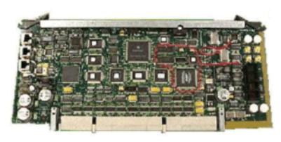
UGUY
Every cabinet contains one UGUY. See (Figure 1-3). The UGUY plugs into the HUCB. It is not hot-swappable. Its MP microprocessor controls power monitor functions, executing the Power Monitor 3 (PM3) firmware and the CLU firmware.
Figure 1-3 UGUY
CLU Functionality
The CLU collects and reports the configuration information for itself, the main backplane, I/O backplanes, and the SUB/HUB. Each of these boards has a configuration EEPROM containing FRUIDs,revisioninformation,andforthemainbackplaneandI/Obackplanes,maximumpower requirements in the fully configured, fully loaded states. These EEPROMs are powered by housekeepingpower(HKP)andareaccessibletoSARGfromanI2Cbus.Thepowerrequirement information is sent to the PM3 automatically when HKP is applied or when a new entity is plugged in. The configuration information is sent to the SUB in response to a get_config command.
The CLU gathers the following information over its five I2C buses:
•Boardrevisioninformationiscontainedintheboard'sconfigurationEEPROMfortheUGUY
board,theSBCHboard,themainbackplane,themainbackplanepowerboards(HBPB),the I/O backplane (HIOB), and the I/O backplane power boards (IOPB).
•Power requirements from the configuration EEPROM for the main backplane (HLSB or HRSB) and the I/O backplanes. This information is sent to the PM3 processor so it can calculate cabinet power requirements.
•Powercontrolandstatusinterface.AnotherfunctionoftheUGUYistousethepower_good signals to drive the power on sequence.
•ResetcontrolwhichincludesaresetforeachI/Obackplane,amainbackplanecabinetreset, TRST - JTAG reset for all JTAG scan chains in the entire cabinet, a system clock control margincontrol,nominalorhighmarginandaclocksourceselectionandinternalorexternal OL* LED control.
•Status LEDs for the SBA cable OL*, the cell OL*, the I/O backplane OL*, the JTAG scan control,thethreescanchainspercell,thethreescanchainsperI/Obackplane,andthethree scan chains on the main backplane.
PM3 Functionality
The PM3 performs the following functions:
Utilities Subsystem |
23 |
1.FEPS control and monitoring.
Superdome has six BPS and the UGUY sends 5V to the BPS for use by the fault collection circuitry.
2.Fan control and monitoring.
In addition to the blowers, there are five I/O system fans above and between the I/O bays. These fans run at full speed all the time. There is no fan speed signal.
3.Cabinet mode and cabinet number fan out.
The surface mount dip switch on the HUCB (UGUY backplane) is used to configure a SuperdomecabinetfornormaluseorasanSD16cabinet. Usethe16-positionthumbswitch on the UGUY to set the cabinet number. Numbers 0-7 are for CPU-oriented cabinets and numbers 8-15 are for I/O-only cabinets.
4.LocalPowerMonitor(LPM)interfaces.Eachbigboard(cellboard,I/Obackplane,andmain backplane) contains logic that controls conversion of 48 V to lower voltages. The PM3 interfacestotheLPMwiththeboard-presentinputsignaltothePM3andthepower-enable output signal from the PM3.
5.Front and rear panel board control.
System Clocks
The sx2000 system clock differs from the sx1000 system clock in that the system clocks are only supplied from the backplane and to the backplane crossbar ASICs and the cell boards. There is no distribution of the system clocks to the I/O backplanes. Instead, independent local clock distribution is provided on the I/O backplane. The system clocks are not provided by the PM3 on sx2000 servers. The sx2000 system clock source resides on the system backplane.
Management Processor
The MP is comprised of two PCBs, the SBC and the SBCH.The MP is a hot-swappable unit powered by +5 V HKP that holds the MP configuration parameters in compact flash and the error and activity logs and the complex identification information or complex profile in battery backed NVRAM. It also provides the USB network controller (MP bus). Each complex has one MP per complex. It cannot be set up for redundancy. However, it is not a single point of failure for the complex because it can be hot-swapped. If the MP fails, the complex can still boot and function. However, the following utility functions are lost until the MP can be replaced:
•Processing and storing log entries (chassis codes)
•Console functions to every partition
•OL* functions
•VFP and system alert notification
•Connection to the MP for maintenance, either locally or remotely
•Diagnostics (ODE and scan)
24 Overview
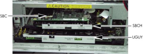
Figure 1-4 Management Processor
The SBCH provides the physical and electrical interface to the SBC, the fanning out of the USB to internal and external subsystems, and a LAN 10/100BT ethernet connection. It plugs into the HUCB and is hot-swappable. Every CPU cabinet contains one SBCH board, but only one SBCH containsanSBCboardusedastheMPforthecomplex. TheremainingSBCHboardsactasUSB hubs.
TheSBCboardisanembeddedcomputerrunningsystemutilityboard(SUB)firmware. Itisthe core of the MP. It plugs into the SBCH board through a PC104 interface. The SBC provides the following external interfaces to the utility subsystem:
•LAN (10/100BT ethernet) for customer console access
•RS232 port for local console access for manufacturing and field support personnel
The modem function is not included on the SBC and must be external to the cabinet.
Compact Flash
TheCompactFlashisaPCMCIA-stylememorycardthatplugsintotheSBCboard. Itstoresthe MP firmware and the customer's MP configuration parameters. The parameters stored in the compact flash are as follows:
•Network configurations for both the public and private LANs
•User name and password combinations for logging in to the MP
•Baud rates for the serial ports
•Paging parameters for a specified alert level
•Configurable system alert parameters
HUCB
The HUCB, shown in Figure 1-5, is the backplane of the utility subsystem. It provides cable distributionforalltheutilitysignalsexcepttheclocks.ItalsoprovidesthecustomerLANinterface andserialports.Thesupportmanagementstation(SMS)connectstotheHUCB.Thesystemtype switch is located on the HUCB. This board has no active circuits. It is not hot-swappable.
Utilities Subsystem |
25 |
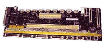
Figure 1-5 HUCB
Backplane
Thesystembackplaneassemblyfabricprovidesthefollowingfunctionalityinansx2000system:
•Interfaces the CLU subsystem to the system backplane and cell modules
•Houses the system crossbar switch fabrics and cell modules
•Provides switch fabric interconnect between multiple cabinets
•Generates system clock sources
•Performs redundant system clock source switching
•Distributes the system clock to crossbar chips and cell modules
•Distributes HKP to cell modules
•Terminates I/O cables to cell modules
Thebackplanesupportsuptoeightcells,interconnectedbythecrossbarlinks. Asustainedtotal bandwidthof25.5GBisprovidedtoeachcell.EachcellconnectstothreeindividualXBCASICs. Thisconnectionenablesasinglechipcrossingwhenacellcommunicateswithanothercellinits four-cell group. When transferring data between cells in different groups, two crossbar links compensate for the resultant multiple chip crossings. This topology also provides for switch fabric redundancy
Dual rack/backplane systems contain two identical backplanes. These backplanes use 12 high-speedinterfacecablesasinterconnectsinsteadoftheflexcableinterfacepreviouslyemployed for the legacy Superdome crossbar. The sustainable bisection bandwidth between cabinets is 72 GB/s at a link speed of 2.1 GT/s.
Crossbar Chip
The crossbar fabrics in the sx2000 are implemented using the XBC crossbar chip. Each XBC is a non-bit-sliced,eight-portnon-blockingcrossbarthatcancommunicatewiththeCCorXBCASICs. Eachoftheeightportsisfullduplex,capableoftransmittingandreceivingindependentpackets simultaneously. Each port consists of 20 channels of IBM's HSS technology. Eighteen channels are used for packet data. One channel is used for horizontal link parity, and one channel is a spare. The HSS channels can run from 2.0- 3.2 GT/s. At 3.0 GT/s, each port provides 8.5 GB/s of sustainable bidirectional data bandwidth.
Like the CC and the SBA, XBC implements link-level retry to recover from intermittent link errors.XBCcanalsoreplaceahard-failedchannelwiththesparechannelduringtheretryprocess, which guarantees continued reliable operation in the event of a broken channel, or single or multibit intermittent errors.
XBC supports enhanced security between hard partitions by providing write protection on key CSRs.Withoutprotection,CSRssuchastheroutingtablescanbemodifiedbyarogueOS,causing otherhardpartitionsinthesystemtocrash.Topreventthis,keyCSRsinXBCcanonlybemodified bypacketswiththeSecurebitset. ThisbitissetbytheCC,basedonaregisterthatissetonlyby
26 Overview
ahardcellreset,whichcausessecurefirmwaretobeentered.Thisbitisclearedbysecurefirmware before passing control to an OS.
Switch Fabrics
The system backplane houses the switch fabric that connects to each of the cell modules. The crossbar switch is implemented by a three-link-per-cell topology: three independent switch fabrics connected in parallel. This topology provides switch fabric redundancy in the crossbar switch. Thebackplanecrossbarcanbeextendedtoanadditionalcrossbarinasecondbackplane foradualbackplaneconfiguration.Itconnectsthroughahigh-speedcableinterfacetothesecond backplane. This 12-cable high-speed interface replaces the flex cable interface previously used on the Superdome system.
Backplane Monitor and Control
The backplane implements the following monitor and control functions:.
•Backplane detect and enable functions to and from the CLU
•Backplane LED controls from the CLU
•Backplane JTAG distribution and chains
•Cabinet ID from the CLU
•Reset and power manager FPGA (RPM) and JTAG interface and header for external programming
•XBC reset, configuration and control
•IIC bus distribution to and from the CLU
•Clock subsystem monitor and control
•Power supply monitor and control
•Cell detect, power monitor, reset and enable to and from the CLU
•JTAG and USB data distribution to and from each cell module
•Cell ID to each cell module
•OSP FPGA functionality
I2C Bus Distribution
The sx2000 system I2C bus extends to the Superdome backplane (SDBP) assembly through a cableconnectedfromtheCLUsubsystem. ThiscableconnectsfromJ17ontheCLUtoJ64onthe SDBP. The clock and data signals on this cable are buffered through I2C bus extenders on the CLU and on the backplane.
TheI2CbusisroutedtoanI2Cmultiplexeronthebackplanewherethebusisisolatedintofour bussegments.ThreebussegmentsarededicatedtoconnectionstothethreeRPMs.Theremaining segmentisusedtodaisy-chaintheremainingaddressabledevicesonthebus. Eachbussegment is addressed through a port on the I2C multiplexer.
Clock Subsystem
The backplane houses two hot-swap oscillator (HSO) modules. Each HSO board generates a system clock that feeds into the backplane. Each HSO output is routed to the redundant clock source(RCS)module. TheRCSmoduleacceptsinputfromthetwoHSOmodulesandproduces asinglesystemclock,whichisdistributedonthebackplanetoallcellmodulesandXBCASICs.
System Clock Distribution
The system components that receive the system clock are the eight cell boards that plug into to the backplane and the six XBC on the system backplane. Two backplane clock power detectors (oneforeach8-waysineclockpowersplitter)areontheRCS. Thebackplanepowerdetectorsits at the end of the clock tree and measures the amplitude of the clock from the RCS to determine
Backplane 27

if it is providing a signal of the correct amplitude to the cell boards and XBCs. Its output is also an alarm signal to the RPM FPGA.
System clocks can originate from these input sources:
•the single-ended external clock input MCX connector
•the 280 MHz margin oscillator on the redundant clock source (RCS) board
•one of the 266.667 MHz oscillators on one of the HSO modules
The source selection is determined either by firmware or by logic in the RCS.
Theclocksourcehasalarmsignalstoindicatethefollowinghealthstatusconditionstothecabinet management subsystem:
•Loss of power and loss of clock for each of the clock oscillator boards
•Loss of clock output to the backplanes
The sx2000 clock system differs from the sx1000 clock system in that the system clocks are only suppliedtothebackplanecrossbarASICsandthecellboards. Systemclocksarenotdistributed to the I/O backplanes. Instead, independent local clock distribution is provided on the I/O backplane.
Hot-Swap Oscillator
Two hot-swappable clock oscillators combine the outputs of both oscillators to form an N+1 redundant fault tolerant clock source. The resultant clock source drives clocks over connector and cable interfaces to the system backplanes.
The HSO board contains a 266.667 MHz PECL oscillator. The output from this oscillator drives a266.667MHzband-passSAWfilterthatdrivesamonolithicICpoweramplifier. Theoutputof the power amplifier is a 266.667 sine wave clock that goes to the RCS. The module also has two LEDs,onegreenandoneyellow,thatarevisiblethroughthemodulehandle.Table1-1 describes the HSO LEDs. The electrical signal that controls the LEDs is driven by the RCS.
Table 1-1 HSO LED Status Indicator Meaning
Green LED |
Yellow LED |
Meaning |
On |
Off |
ModuleOK.HSOisproducingaclockofthecorrectamplitudeandfrequency |
|
|
and is plugged into its connector. |
Off |
On |
Moduleneedsattention.HSOisnotproducingaclockofthecorrectamplitude |
|
|
or frequency, but it is plugged into its connector. |
Off |
Off |
Module power is off. |
sx2000 RCS Module
The sx2000 RCS module supplies clocks to the Superdome sx2000 backplane, communicates clockalarmstotheRPM,andacceptscontrolinputfromtheRPM. IthasanI2CEEPROMonthe module so that the firmware can inventory the module on system power on.
TheRCSsupplies16copiesofthesinewavesystemclocktothesx2000systembackplane. Eight copiesgototheeightcellboards,sixcopiesgotothesixXBCsonthesystembackplane,andtwo copies to the backplane clock power detector.
Innormaloperation,theRCSselectsoneofthetwoHSOsasthesourceofclocksfortheplatform. The HSO selected depends on whether the HSO is plugged into the backplane and on whether it has a valid output level. This selection is overridden if there is a connection from the clock input MCX connector on the master backplane. Figure 1-6 shows the locations of the HSOs and RCS on the backplane.
28 Overview
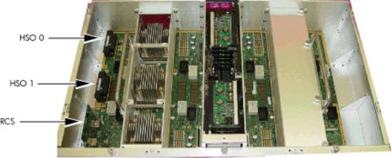
Figure 1-6 HSO and RCS Locations
IfonlyoneHSOispluggedinanditsoutputisofvalidamplitude,thenitisselected.Ifitsoutput is valid, then a green LED on the HSO is lit. If its output is not valid, then a yellow LED on the HSOlightsandanalarmsignalgoesfromtheRCStotheRPM. TheRCSprovidesaclockthatis approximately 100 KHz less than the correct frequency, even if the output of the HSOs are not of valid amplitude or no HSOs are plugged in.
IfbothHSOsarepluggedinandtheiroutputamplitudesarevalid,thenoneofthetwoisselected as the clock source by logic on the RCS. The green LEDs on both HSOs light.
IfoneoftheHSOsoutputsdoesnothavethecorrectamplitudethentheRCSusestheotherone as the source of clocks and sends an alarm signal to the RPM indicating which oscillator failed. The green LED lights on the good HSO and the yellow LED lights on the failed HSO.
If an external clock cable is connected from the master backplane clock output MCX connector to the slave backplane clock input MCX connector, then this overrides any firmware clock selections. The clock source from the slave backplane becomes the master backplane.
If firmware selects the margin oscillator as the source of clocks, then it is the source of clocks as long as there is no connection to the clock input MCX connector from the master backplane.
If the firmware selects the external margin clock SMB connectors as the source of clocks, then it isthesourceofclocksaslongasnoconnectionexiststotheclockinputMCXconnectorfromthe master backplane.
Cabinet ID
The backplane receives a 6-bit cabinet ID from the CLU interface J64 connector. The cabinet ID is buffered and routed to each RPM and to each cell module slot. The RPM decodes the cabinet number from the cabinet ID and uses this bit to alter the cabinet number bit in the ALBID byte sent to each XBC through the serial bit stream.
Cell ID
The backplane generates a 3-bit slot ID for each cell slot in the backplane. The slot ID and five bits from the cabinet ID are passed to each cell module as the cell ID.
Backplane Power Requirements and Power Distribution
Thedcpowersupplyforthebackplaneassemblyrunsfromthecabinetpowersupplysubsystem through two power cables attached to the backplane. Connectors for the dc supply input have the same reference designators and are physically located in the same position as on the Superdomesystembackplane.ThepowercablesarereusedcableassembliesfromtheSuperdome systemandthesupplyconnectionisnotredundant. Onecableisusedforhousekeepingsupply input. A second cable is used for 48 V supply input.
Backplane 29
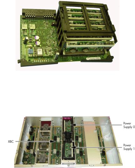
The backplane has two slots for power supply modules. The power supply connector for each slothasa1-bitslotaddresstoidentifytheslot.Theaddressbitforpowersupplyslot0isgrounded. The address bit for slot 1 floats on the backplane. The power supply module provides a pull-up resistor on the address line on slot 1. The power supply module uses the slot address bit as bit A0 for generating a unique I2C address for the FRU ID prom. Figures 1-7 and 1-8 identify and show the location of the backplane power supply modules.
Figure 1-7 Backplane Power Supply Module
Eachpowersupplyslothasapowersupplydetectbitthatdeterminesifthepowersupplymodule isinsertedintothebackplaneslot.ThisbitisroutedtoaninputontheRPMs.TheRPMprovides apull-upresistorforlogic1whenthepowersupplymoduleismissing.Whenthepowersupply module is inserted into the slot, the bit is grounded by the power supply and logic 0 is detected by the RPM, indicating that the power supply module is present in the backplane slot.
Figure 1-8 Backplane (Rear View)
CPUs and Memories
The cell provides the processing and memory resources required by each sx2000 system configuration. Each cell includes the following components: four processor module sockets, a single cell (or coherency) controller ASIC, a high-speed crossbar interface, a high-speed I/O interface,eightmemorycontrollerASICs,capacityforupto32double-datarate(DDR)DIMMs, high-speedclockdistributioncircuitry,amanagementsubsysteminterface,scan(JTAG)circuitry for manufacturing test, and a low-voltage DC power interface. Figure 1-9 shows the locations of the major components.
30 Overview
Loading...