


 Loading...
DVG-6004S/6008S
VoIP Gateway
User’s Manual
Version 1.3
(29 April 2008)
© 2008 D-Link Corporation. All rights reserved.
Reproduction in any manner whatsoever without the written permission of D-Link Corporation is strictly forbidden.
Trademarks used in this text: D-Link and the D-Link logo are trademarks of D-Link Corporation/D-Link Systems Inc.; Other trademarks and trade names may be used in this document to refer to either the entities claiming the marks and names or their products. D-Link Corporation disclaims any proprietary interest in trademarks and trade names other than its own.
Warranty: please contact your D-Link Authorized Reseller or the D-Link Branch Office nearest your place of purchase for information about the warranty offered on your D-Link product.
Information in this document is subject to change without notice.
FCC Warning
This equipment has been tested and found to comply with the limits for a Class B digital device, pursuant to Part 15 of the FCC Rules. These limits are designed to provide reasonable protection against harmful interference in a residential installation. This equipment generates, uses, and can radiate radio frequency energy and, if not installed and used in accordance with the instructions, may cause harmful interference to radio communication. However, there is no guarantee that interference will not occur in a particular installation. If this equipment does cause harmful interference to radio or television reception, which can be determined by turning the equipment off and on, the user is encouraged to try to correct the interference by one or more of the following measures:
Reorient or relocate the receiving antenna.
Increase the separation between the equipment and receiver.
Connect the equipment into an outlet on a circuit different from that to which the receiver is connected.
Consult the dealer or an experienced radio/TV technician for help.
CE Mark Warning
This is a Class B product. In a domestic environment, this product may cause radio interference in which case the user may be required to take adequate measures.
Warnung!
Dies ist ein Produkt der Klasse B. Im Wohnbereich kann dieses Produkt Funkstoerungen verursachen. In diesem Fall kann vom Benutzer verlangt werden, angemessene Massnahmen zu ergreifen.
Precaución!
Este es un producto de Clase B. En un entorno doméstico, puede causar interferencias de radio, en cuyo case, puede requerirse al usuario para que adopte las medidas adecuadas.
Attention!
Ceci est un produit de classe B. Dans un environnement domestique, ce produit pourrait causer des interférences radio, auquel cas l`utilisateur devrait prendre les mesures adéquates.
Attenzione!
Il presente prodotto appartiene alla classe B. Se utilizzato in ambiente domestico il prodotto può causare interferenze radio, nel cui caso è possibile che l`utente debba assumere provvedimenti adeguati.
Contents |
|
1. Introduction .................................................................................................... |
1 |
1-1 Product Overview.................................................................................................................................... |
1 |
1-2 Hardware Description ............................................................................................................................. |
2 |
2. Installation and Applications......................................................................... |
4 |
2-1 Network Interface.................................................................................................................................... |
4 |
2-2 Telephone Interface Description............................................................................................................. |
6 |
3. Gateway Configuration – Use Web Browser ............................................... |
7 |
3-1 Network Settings (WAN) ......................................................................................................................... |
8 |
3-2 Network Settings (LAN) ........................................................................................................................ |
12 |
3-3 QoS Settings ......................................................................................................................................... |
14 |
3-4 NAT/DDNS............................................................................................................................................ |
16 |
3-5 Caller ID ................................................................................................................................................ |
19 |
3-6 Telephony Settings ............................................................................................................................... |
21 |
3-7 SIP ........................................................................................................................................................ |
25 |
3-8 Calling Features.................................................................................................................................... |
30 |
3-9 Advanced Options................................................................................................................................. |
31 |
3-10 Digit Map ............................................................................................................................................. |
35 |
3-11 Phone Book......................................................................................................................................... |
39 |
3-12 Caller Filter.......................................................................................................................................... |
40 |
3-13 CDR Settings ...................................................................................................................................... |
41 |
3-14 Language ............................................................................................................................................ |
42 |
3-15 Transit Call Control ............................................................................................................................. |
43 |
3-16 Long-Distance Control Table .............................................................................................................. |
44 |
3-17 Long Distance Exception Table .......................................................................................................... |
45 |
3-18 CPT/Cadence Settings ....................................................................................................................... |
46 |
3-19 Current Status..................................................................................................................................... |
48 |
3-20 RTP Packet Summary ........................................................................................................................ |
49 |
3-21 System Information ............................................................................................................................. |
50 |
3-22 Routing Table...................................................................................................................................... |
51 |
3-23 STUN Inquiry....................................................................................................................................... |
52 |
3-24 Ping Test ............................................................................................................................................. |
53 |
3-25 Static Route......................................................................................................................................... |
54 |
3-26 Port Filtering........................................................................................................................................ |
55 |
3-27 IP Filtering ........................................................................................................................................... |
56 |
3-28 MAC Filtering ...................................................................................................................................... |
57 |
3-29 Virtual Server ...................................................................................................................................... |
58 |
3-30 DMZ .................................................................................................................................................... |
59 |
3-31 URL Filter ............................................................................................................................................ |
60 |
3-32 Special Applications............................................................................................................................ |
61 |
3-33 DoS Prevention Settings..................................................................................................................... |
62 |
3-34 NTP (Network Time Protocol) ............................................................................................................. |
63 |
3-35 SNMP.................................................................................................................................................. |
64 |
3-36 Backup/Restore .................................................................................................................................. |
65 |
3-37 System Log ......................................................................................................................................... |
66 |
3-38 Provision Settings ............................................................................................................................... |
67 |
3-39 System Operations (Save Settings).................................................................................................... |
68 |
3-40 Software Upgrade ............................................................................................................................... |
69 |
3-41 Logout ................................................................................................................................................. |
70 |
4. |
Configuring the Gateway through IVR ....................................................... |
71 |
|
|
4-1 IVR (Interactive Voice Response)......................................................................................................... |
71 |
|
|
4-2 |
IP Configuration Settings—Set the IP Configuration of the WAN Port ................................................. |
73 |
5. |
Dialing Principles ......................................................................................... |
76 |
|
|
5-1 |
Dialing Options...................................................................................................................................... |
76 |
|
5-2 |
Dialed Number Processing Flow........................................................................................................... |
76 |
|
5-3 |
Example for Match phone numbers invited by callers .......................................................................... |
77 |
Appendix........................................................................................................... |
79 |
||
|
Product Features List .................................................................................................................................. |
79 |
|

DVG-6004S/6008S User’s Manual |
Product Overview |
1. Introduction
1-1 Product Overview
The DVG-6004S/6008S VoIP Gateway carries both voice and facsimile over the IP network. It uses the industry standard SIP call control protocol so as to be compatible with free registration services or VoIP service providers’ systems. As a standard user agent, it is compatible with all common Soft Switches and SIP proxy servers. While running optional server software, the gateway can be configured to establish a private VoIP network over the Internet without a third-party SIP Proxy Server.
The gateway can be seamlessly integrated into an existing network by connecting to a phone set and fax machine. With only a broadband connection such as an ADSL bridge/router, a Cable Modem or a leased-line router, the gateway allows you to use voice and fax services over IP in order to reduce the cost of all long distance calls.
DDNS support makes the gateway reachable via its domain name where an ISP dynamically assigns an IP address. By enabling the CDR function, administrators are allowed to log-in and view all call records, for example call duration, time and date of calls, and latency.
The gateway can be assigned a fixed IP address or it can have one dynamically assigned by DHCP over PPPoE. It adopts either the G.711, G.726, G.729A or G.723.1 voice compression format to save network bandwidth while providing real-time, toll quality voice transmission and reception.
D-Link Systems, Inc. |
1 |
DVG-6004S/6008S User’s Manual |
Hardware Description |
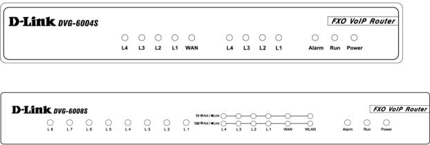
1-2 Hardware Description
Front Panel
DVG-6004S
DVG-6008S
yPower Indicator: green light indicates a normal power supply.
yRun Indicator: blinking green light indicates normal operation.
yAlarm Indicator: when the system starts up, the red light will blink. This indicator will also light to indicate any abnormal gateway behavior.
yL1 – L8 stands for Port 1 – Port 8: Connect to your original telephone line on the wall jack with RJ-11 cable.
yWAN Indicators: indicate connection and activity on the WAN Ports.
yL1 – L4 Indicators: indicate connection and activity on LAN Port 1 – 4.
9When starting up the system, the Alarm, Run, and Power indicators will light up. After about 40 seconds, the Alarm indicator will go off, the Run indicator will blink green, and the Power indicator will stay green (under normal operating conditions). If the Alarm indicator continues to blink, then the system is attempting to connect with your ISP and has yet to obtain an IP address.
9Once the WAN is connected, the WAN indicator will light up green and, if data is being transmitted over the Internet, the indicator blinks green and orange.
D-Link Systems, Inc. |
2 |
DVG-6004S/6008S User’s Manual |
Hardware Description |
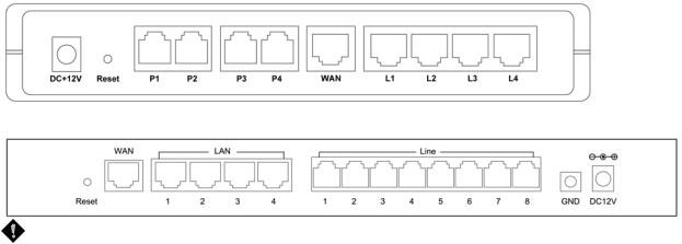
Rear Panel
DVG-6004S
DVG-6008S
WARNING: DO NOT (1) connect the phone ports to each other (FXO to FXO) or (2) connect any phone port (FXO) directly to a Phone set. Doing so may damage your VoIP gateway.
To restore factory default settings (IP address, User’s Name, Password):
(1)Disconnect the power plug.
(2)Press and hold the reset button for 6 seconds.
(3)Reconnect the power plug while pressing down on the reset button.
(4)Release the reset button after 6 seconds. Factory settings will be restored.
D-Link Systems, Inc. |
3 |

DVG-6004S/6008S User’s Manual |
Network Interface |
2. Installation and Applications
2-1 Network Interface
The network interface is divided into three basic modes as described below:
yGateway can be assigned a Public IP Address
yGateway can be built under the existing NAT
yGateway can be assigned a Public IP address and serve as an IP-sharing router.
 NOTE: The Network Interface function mode setup is accessed through a web UI.
Gateway Assigned a Public IP Address
The gateway will have a public IP address for Internet connection regardless of whether the IP is a static IP address, DHCP (using a Cable Modem), or PPPoE (Dial-up / ADSL).
Gateway IP Settings |
Need to be set up as static IP, |
|
|
DHCP, or PPPoE |
|
NAT/STUN Settings |
Unnecessary (Disabled) |
|
DDNS Settings |
Unnecessary (Disabled) |
|
|
|
|
Gateway in a NAT Network
Under this mode, the gateway uses a virtual IP address and the IP sharing function of other systems to connect to the Internet.
LAN IP address for IP sharing |
Please avoid IP addresses in the following range: |
||
|
192.168.8.1-192.168.8.254 (You may need to change the settings of |
||
|
IP sharing or change SIP series gateway LAN Port IP addressing) |
||
Gateway IP Settings |
Set as static IP address, and assign the LAN IP address of the IP |
||
|
sharing to the Default Gateway. |
||
NAT /STUN Settings |
Enable |
If the WAN of the IP sharing device has a static IP address, |
|
|
|
then the NAT IP address is set as the Public IP address for |
|
|
|
IP sharing. |
|
|
|
|
|
|
|
If the WAN of the IP sharing device uses a dynamic IP |
|
|
|
address, then the gateway has to comply with the DDNS |
|
|
|
settings. When using NAT, you must enter the URL |
|
|
|
(Uniform Resource Locator) that is registered to the DDNS |
|
|
|
server. |
|
DDNS Settings |
The WAN of the IP |
Disabled |
|
|
sharing device has a |
|
|
|
static IP address. |
|
|
|
The WAN of the IP |
Enabled: enter the registered URL (Uniform |
|
|
sharing device has a |
Resource Locator) into the network settings |
|
|
dynamic IP address. |
under NAT |
|
D-Link Systems, Inc. |
4 |
DVG-6004S/6008S User’s Manual |
Network Interface |
Gateway assigned a Public IP Address and serving as an IP sharing device
The gateway will have a public IP address regardless of whether it is a static IP application, DHCP (using a Cable Modem), or PPPoE (to connect to your ADSL account), which can then use the functions of built-in IP sharing to allow other PCs to be on-line at the same time.
Gateway IP Settings |
Need to be set up as static IP, DHCP, or PPPoE |
|
NAT/STUN Settings |
Unnecessary (Disabled) |
|
DDNS Settings |
Unnecessary (Disabled) |
|
PC IP Address Settings |
PCs should use a static IP address in the |
|
(for IP sharing through the |
following range : 192.168.8.1-192.168.8.253 |
|
gateway) |
Subnet Mask : 255.255.255.0 |
|
|
Default Gateway : 192.168.8.254 |
|
D-Link Systems, Inc. |
5 |
DVG-6004S/6008S User’s Manual |
Telephone Interface Description |
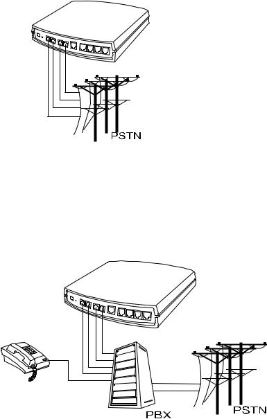
2-2 Telephone Interface Description
Example for DVG-6004S/6008S:
DVG-6004S/6008S connecting directly to the Telephone Line of a PSTN
L1-L4 or L1-L8 is FXO interfaces and can all be connected to a PSTN to serve as a bridge between the PSTN and other VoIP telephones. The system also allows a call to be made from a traditional telephone line to connect with a user behind the Gateway.
Integrating the DVG-6004S/6008S with a PBX
DVG-6004S/6008S connecting directly to the Telephone Line of a PSTN
L1L4 or L1-L8 is FXO interfaces, and some of them can be connected to PSTN for direct calls. Others can be connected to the PBX so other extension lines can make VoIP calls by calling extension phone number.
.
D-Link Systems, Inc. |
6 |
DVG-6004S/6008S User’s Manual |
Gateway Configuration-Web Browser |
3. Gateway Configuration – Use Web Browser
The VoIP gateway allows users to configure its settings using a web interface (Web UI). You can access the Configuration Menu by opening a web-browser (e.g., Internet Explorer or Netscape Navigator) and entering the factory default LAN IP address: 192.168.8.254. The IP address of the Web UI is same as the default LAN IP noted elsewhere in this user’s manual.
You can also use an ordinary telephone, connect it to the gateway, and dial ”101” to inquire about the current WAN Port IP address and then use the WAN port to log-in.
Instructions
yOpen a Web-Browser (e.g., Explorer, Navigator, Opera, Firefox).
yEnter the LAN port IP address. The default LAN port IP address is: 192.168.8.254.
yThe log-in screen below will appear after you connect. (The factory default settings for Login ID and Password are blank (i.e., no login ID, no password).)
The gateway does not allow multiple people to configure the gateway simultaneously. Please remember to logout or restart the system if you are not using the web configuration function.
D-Link Systems, Inc. |
7 |
DVG-6004S/6008S User’s Manual |
Network Settings |
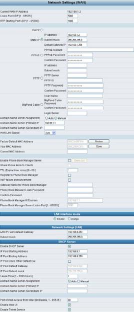
3-1 Network Settings (WAN)
The network settings are used to set the gateway’s communication ports, IP configurations, and Phone Book Manager IP settings.
yCurrent WAN IP Address: The IP address of the WAN port.
yListen Port UDP: It is not necessary to change the protocol of the communication port used by the gateway, unless it conflicts with ports used by another device in your network.
yRTP Starting Port UDP: The initial value of the port number for transmitting voice data among gateway(s). Each line requires 2 ports. It is not necessary to change the setting, unless it conflicts with ports used by another network device.
For example, if the starting port is 9000, then Line 1 is using ports 9000 and 9001, and Line 2 is using ports 9002 and 9003, and so forth.
D-Link Systems, Inc. |
8 |
DVG-6004S/6008S User’s Manual |
Network Settings |
IP Configuration (Setting WAN Port)
There are five methods of obtaining a WAN port IP address:
1.Static IP
2.DHCP, which means a Dynamic IP (Cable Modem)
3.PPPoE (dial-up ADSL)
4.PPTP
5.BigPond (for Australia only)
Methods for using DHCP and PPPoE for obtaining an IP address may vary. If you are not familiar with creating a network connection, please contact your local ISP.
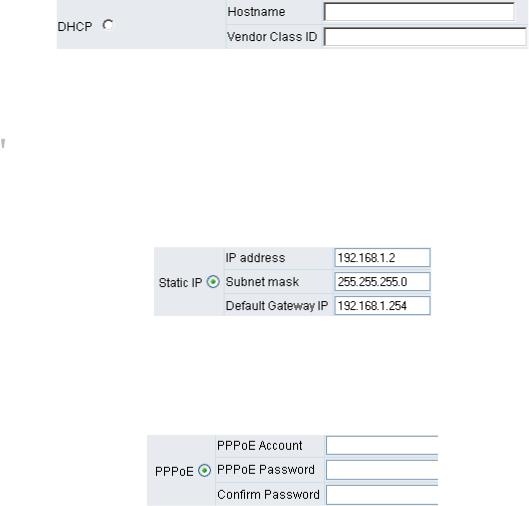
Setting Dynamic IP (DHCP)
Click “DHCP” to obtain a Dynamic IP address, enter the “Hostname” and “Vendor Class ID” if required by your local ISP and then click the “Accept” button at the bottom of the screen.
Saving the settings: Click System Operation to select “Save Settings”, “Restart”, and then click the ”Accept” button. Wait for about 40 seconds, and the system will obtain the required IP value from the DHCP Server.
 NOTE: After the system has obtained a new IP address, if you are using a WAN port to enter the Web Configuration Screen, the new IP address has to be used. The same principle applies to the next two settings.
Setting Static IP
Select “Static IP” and enter the IP address, Subnet Mask and Default Gateway values. Then click the “Accept” button at the bottom of the screen. Save the settings, and then restart the system. Wait for about 40 seconds for the system to restart.
ADSL PPPoE Settings
Select “PPPoE” and enter the Account Number, Password and Reenter Password to confirm. Then click the “Accept” button at the bottom of the screen. Save the settings, and then restart the system. The system will take about 49 seconds to restart.
D-Link Systems, Inc. |
9 |
DVG-6004S/6008S User’s Manual |
Network Settings |
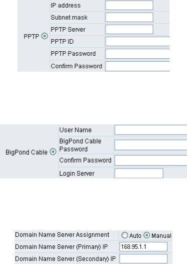
PPTP
Select “PPTP” and enter the IP Address, Subnet mask, PPTP Server, PPTP ID and Password. Then click the “Accept” button at the bottom of the screen.
BigPond (for Australia only)
Click “BigPond Cable” and enter the User Name and Password. Then click the “Accept” button at the bottom of the screen.
(DNS) Settings
Domain Name Server (DNS): While a gateway is accessing another gateway or a computer with a hostname, it will look up the IP address from the DNS provided by your ISP. Normally, the ISP assigns DNS information while negotiating with PPPoE or DHCP. If the DNS is not assigned automatically or the WAN port is assigned a static IP address, the DNS settings must be assigned manually.
Auto: the gateway learns primary and secondary addresses from the ISP’s DHCP server or PPPoE server.
Manual: enter the primary and secondary addresses manually. Please be sure that the IP addresses are correct otherwise the gateway will not be able to access hosts using hostnames instead of IPs.
D-Link Systems, Inc. |
10 |
DVG-6004S/6008S User’s Manual |
Network Settings |
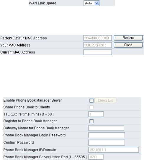
WAN Link Speed
It is used to choose the WAN Ethernet link speed. The default is Auto. Please choose the same speed with Router/Switch/Hub, if VoIP gateway connected to Router/Switch/Hub has the link problem.
Clone MAC
Some Internet Service Providers (ISPs) assign bandwidth via MAC (Media Access Control) addresses. You can click the "Clone" button to type in a MAC address which will be recognized by your ISP. It is only necessary to fill in the field if it is required by your ISP.
The “Your MAC Address” field will be blank as you log-in via the WAN port.
Using Phone Book Manager
yEnable Phone Book Manager Server: this allows other gateway users to register the IP address and telephone number in this Phone Book manager. It is recommended that the unit appointed as the Phone Book Manager use static IP.
yShare Phone Book to Clients: While this option is enabled and the gateway is performing as a Phone Book Manager, this gateway will append its Phone Book entries to the Manager for other clients to lookup.
yTTL (Time to Live): If a gateway system that is controlled by the Phone Book Manager does not report back within the deadline set by TTL, the system will be excluded from the user’s list. Each gateway should report to the Phone Book Manager once every 30 seconds.
yRegister to Phone Book Manager: To register to the Phone Book Manager.
yGateway Name for Phone Book Manager: The alias registered with the Phone Book Manager.
yPhone Book Manager Login Password: Enter the registered password. If this system is serving as the Phone Book Manager, the set password is also the password used for registering other gateway systems.
D-Link Systems, Inc. |
11 |

DVG-6004S/6008S User’s Manual |
Network Settings |
yPhone Book Manager IP/Domain: Enter the IP address for the Phone Book Manager. (This variable also supports URL (Uniform Resource Locator).)
yPhone Book Manager Server Listen Port [1 - 665535]: The protocol communication port for transmitting signals between the Phone Book Manager and other gateway systems. Please confirm whether or not the setting is the same as that of the Phone Book Manager.
3-2 Network Settings (LAN)
yRouter: The system serves as a Router with NAT.
yBridge: The system serves as a Bridge between WAN port and LAN port without NAT. (LAN default gateway will still be accessible for configuration).
Gateway LAN Port IP address and subnet mask settings.
D-Link Systems, Inc. |
12 |
DVG-6004S/6008S User’s Manual |
Network Settings |
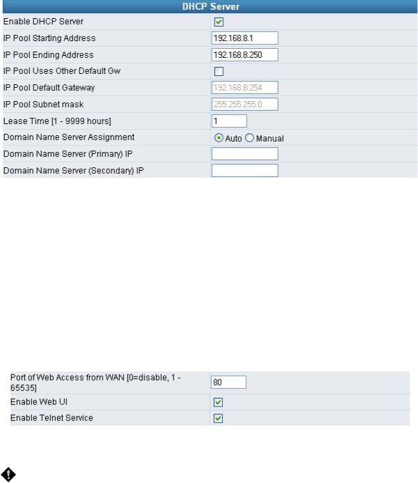
yEnable DHCP Server: Enable or Disable DHCP server service of the gateway.
yIP Pool Starting Address: The first IP address to be assigned to DHCP clients.
yIP Pool Ending Address: The last IP address to be assigned to DHCP clients.
yIP Pool Uses Other Default Gw: Tick the check box to give DHCP client the other default gateway.
yIP Pool Default Gateway: Assign the default gateway and subnet mask to DHCP client.
yIP Pool Subnet mask: Assign the default gateway and subnet mask to DHCP client.
yLease Time: The valid period of an assigned IP address.
yDomain Name Server Assignment: The DNS information to be assigned to DHCP clients.
Auto: the gateway learns primary and secondary addresses from the ISP’s DHCP server or PPPoE server.
Manual: enter the primary and secondary addresses manually. Please be sure that the IP addresses are correct otherwise the gateway will not be able to access hosts using hostnames instead of IPs.
yPort of Web Access from WAN: HTTP port for WAN. To change this setting, web configuration must be accessed via the gateway’s LAN port. The gateway always uses port 80 for HTTP connection via the LAN port.
NOTE: Due to network security concerns, Web Access for WAN port is disabled by default (port number “0” in this option means disable web access). To enable it, simply enter a valid port number in this field.
yEnable Web UI: When “Enable Web UI” is un-ticked, you cannot access from Web.
yEnable Telnet Service: It is to activate Telnet access from WAN or LAN when ticked. You can configure all settings on web user interface through telnet, such as IP configuration, SIP settings, Provision settings, reset to a default stat, etc.
D-Link Systems, Inc. |
13 |
DVG-6004S/6008S User’s Manual |
QoS Settings |
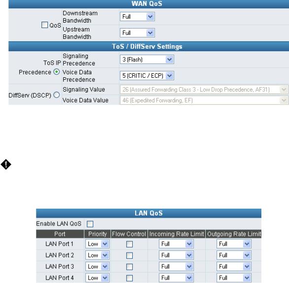
3-3 QoS Settings
WAN QoS
yQoS (Quality of Service): Sets true bandwidth of your Internet connection to ensure sound quality during transmission. (When this function is enabled, voice packets have the highest priority to ensure telecommunication quality while less bandwidth is assigned for data transmission.) Some models of the VoIP gateway without this function will adjust bandwidth automatically.
yToS/DiffServ (Type of Service/DSCP): Voice packets have the highest priority to ensure telecommunication quality; the larger the value you set, the higher the priority.
NOTE: Please contact your ISP when you configure these values.
LAN QoS
yPriority: The gateway can prioritize LAN ports. Data from HIGH priority port are delivered prior to those from LOW priority port while they arrive at the same time.
yFlow Control: Enable or Disable Flow control.
yIncoming Rate Limit: Set the incoming (from WAN to LAN) rate limit of a specific LAN port (can not exceed the real downstream bandwidth).
yOutgoing Rate Limit: Set the outgoing (from LAN to WAN) rate limit of a specific LAN port (can not exceed the real upstream bandwidth).
D-Link Systems, Inc. |
14 |

DVG-6004S/6008S User’s Manual |
QoS Settings |
* VLAN – This feature is only supported for the special hardware.
VLAN is optional. It works with the Router or Switch that supports VLAN. There are 2 VLAN groups: Voice and data (LAN). This improves efficiency of network performance and security.
yEnable VLAN Tagging: It is to tag the packets for VLAN Router or Switch identifying.
yVLAN ID: It is to assign uniquely a user-defined ID to each packet.
yPriority: It is the proprietary to VLAN Router or Switch.
 Note: Please do not change anything here unless requested by your ISP.
D-Link Systems, Inc. |
15 |
DVG-6004S/6008S User’s Manual |
NAT/DDNS |
3-4 NAT/DDNS
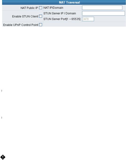
NAT Traversal
If your gateway is set up behind an Internet sharing device, you can select either the NAT or STUN protocol.
yNAT Public IP: The IP address used by the gateway should be a private address. Furthermore, users must set Virtual Server Mapping in the Internet sharing device. (For example, a virtual server is usually defined as a Service Port, and all requests to this port will be redirected to this specified server’s private IP address).
The default ports of the gateway are listed below:
Listen Port (UDP): 5060
RTP Starting Port (UDP): Listen Port used for telephone communication.
Port of Web Access from WAN (TCP): the number you set in this option on the Network Settings page.
DVG-6004: 9000~9023
DVG-6008: 9000~9047
oNAT IP/Domain: Enter the NAT Server IP address (real public IP address of the Internet sharing device); or enter a true URL (Uniform Resource Locator) when DDNS is used. Please refer to the DDNS settings.
 NOTE: If you are setting a public IP in this field, it has to be a static public IP, otherwise VoIP communication may not be established properly. Please contact your ISP to check whether your Internet connection has static public IP addresses.
yEnable STUN Client: Using the STUN protocol prevents problems with setting the IP sharing function, but some NATs do not support this protocol.
 NOTE: You can use the “Status Æ STUN Inquiry” page to detect the NAT type of your Internet sharing device. If the NAT type is “Symmetric NAT,” then the gateway is not able to traverse the NAT. It is not a flaw of the gateway design, but rather a limitation of the STUN protocol.
ySTUN Server IP/Domain and Port: Enter the STUN server IP address and Listen Port number. You can set two STUN server IPs separated by a semicolon.
yEnable UPnP Control Point: This variable will enable the gateway’s IP traffic to pass through an Internet sharing device. This function only works when the Internet sharing device supports UPnP and has it enabled.
NOTE: The “Status Æ Current Status” page will show the status of UPnP.
D-Link Systems, Inc. |
16 |
DVG-6004S/6008S User’s Manual |
NAT/DDNS |
DDNS
D-Link Systems, Inc. |
17 |
DVG-6004S/6008S User’s Manual |
NAT/DDNS |
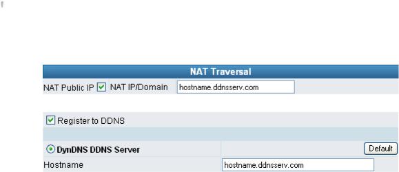
These settings are only necessary when the gateway is set up behind an Internet sharing device that uses a dynamic IP address and does not support DDNS.
Choose a DDNS Server: The current system allows users to choose either DynDNS TZO 3322.org PeanutHull or a private server. You will need to apply for an account with DynDNS TZO 3322.org PeanutHull or a private server before you type in the following information.
yServer address: the IP address or URL (Uniform Resource Locator) of the DDNS Server.
yHostname: the URL of the system (or NAT) – applied from domain name registration providers (e.g. www.dyndns.org).
yLogin ID and Password: The ID and password used to log-in to the DDNS server.
yBehind NAT: Select this only when the system is set up behind a NAT device.
 NOTE: If the gateway is set up under NAT, then enter the hostname in the NAT IP/Domain that is the same as the Hostname of the DDNS.
Example:
NAT
DDNS
D-Link Systems, Inc. |
18 |
DVG-6004S/6008S User’s Manual |
Caller ID |
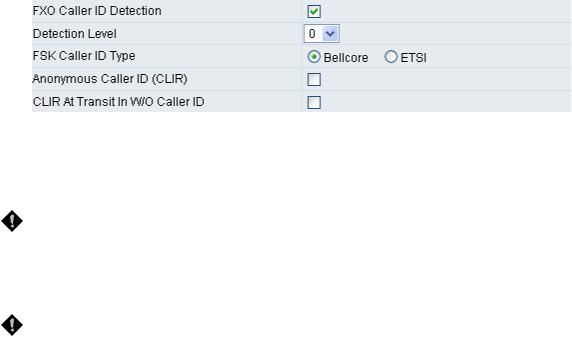
3-5 Caller ID
yFXO Caller ID Detection: Used to detect the Caller ID delivered from the PSTN to the FXO port. When enabled, the Caller ID detected on the FXO port will be sent to the SIP Proxy Server on transit in (dialing out) calls.
yDetection Level: If FXO can’t detect Caller ID, try to adjust it until it can.
NOTE: If you register the gateway to a Proxy, you may be unable to make a call because the gateway will not send the number for authorization.
yFSK Caller ID Type: Bellcore is used in Australia caller ID standards.
yAnonymous Caller ID (CLIR): When enabled, anyone receiving a call from you will not display your number if they have caller ID.
NOTE: If you register the gateway to a Proxy and you check this option, you may be unable to make a call. This is due to the fact that the VoIP gateway doesn’t send the number for authorization.
yCLIR At Transit In W/O Caller ID: When not enabled, if the FXO can detect caller ID in a call from PSTN, the gateway will use the detected caller ID as caller identification when it makes transit in calls; if FXO cannot detect caller ID in a call from PSTN, the gateway will use “anonymous” as caller identification for transit in calls. When it enabled, the gateway will always uses “anonymous” as caller identification for transit in calls.
D-Link Systems, Inc. |
19 |
DVG-6004S/6008S User’s Manual |
Caller ID |
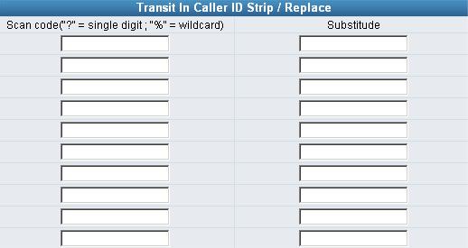
Transit In Caller ID Strip / Replace
yScan code: Defines the rule of the Caller IDs detected by FXO. It can be a prefix or a full number.
ySubstitude: Defines the changed display info. of the calling party while making calls to Internet by FXO.
D-Link Systems, Inc. |
20 |
DVG-6004S/6008S User’s Manual |
Telephony Settings |
3-6 Telephony Settings
Prefix Number Rules
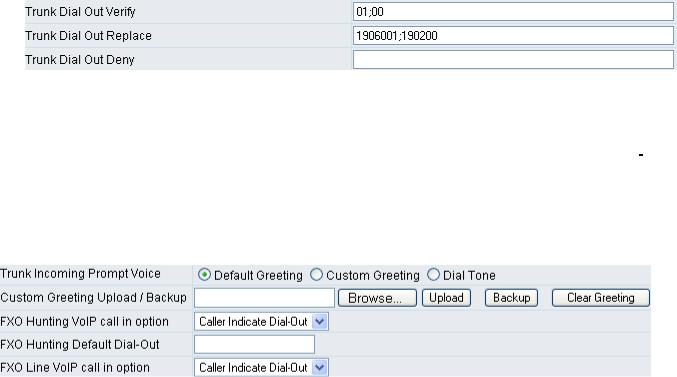
yTrunk Dial Out Verify/ Trunk Dial Out Replace: VoIP gateway will check (verify) the dial out prefix from dial out numbers and change (replace) the prefix to transit out through FXO port.
Example:
If you transit out with 01907123456, the system will transfer to 190601 907123456. If you transit out with 008621123456 the system will replace it with 190200 8621123456. The maximum digit is 40. In the example is 13 digits.
yTrunk Dial Out Deny: The system will deny the call with the leading number filled in this column.
yTrunk Incoming Prompt Voice: Select the greeting (must use the IVR 132 function to record a voice file) when FXO receives an inbound call (transit in).
yFXO Hunting VoIP call in option: To set FXO transit out to POTS mode. By using a fixed number assigned in “FXO Hunting Default Dial-Out “. Or transit out with the number sent from remote SIP UA when the VoIP call calls FXO hunting number.
yFXO Hunting Default Dial-Out: To set FXO default dial-out number.
This will take effect as FXO Line VoIP call in option is set to Default Dial-Out. When some one makes a call to this FXO port from Internet, it will dial to PSTN with that default number.
yFXO Line VoIP call in options: To set FXO dial-out mode when the VoIP call indicates the FXO extension number.
yCaller Indicate Dial-Out: When someone makes a call to this FXO port from Internet, it will dial to PSTN with the number assigned in SIP packet.
yDefault Dial-Out: When some one makes a call to this FXO port from Internet, it will dial to PSTN with the number filled in “FXO Line Default Dial-Out”.
D-Link Systems, Inc. |
21 |
DVG-6004S/6008S User’s Manual |
Telephony Settings |
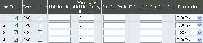
yEnable: Enable a line; if some lines are not used, disable them (Pause Function) to avoid unnecessary waiting when an incoming call is diverting to this line.
yHot Line: When receiving a call from an outside line, the gateway will divert the call to the assigned hotline number.
yHot Line No.: Enter the hot line number for an automatic dialing function.
yWarm Line: When the Warm Line function is in use, user can dial a number. Otherwise the system will divert incoming calls from an outside line to the Hot Line Number after a set wait time.
Example:
Assume the assigned hotline for DVG-6004S/6008S line 1 is 701 and the Warm Line (Hot Line Delay) is 5 seconds. If no extension number is dialed within 5 seconds, the call will be automatically diverted to the assigned hotline (ext 701). The system allows users to record a voice prompt (e.g. “please enter an extension number or wait for the operator to connect you”) to use in this situation.
Assume the assigned hotline for DVG-6004S/6008S line 2 is 702 and the wait time is 0 second. When Port2 receives a call from an outside line, it will be automatically diverted to extension 702.
yDial-out Prefix: It is the number dialed automatically by the system when the FXO interface diverts a call to the PSTN by VoIP.
yFXO Line Default Dial-Out: Default number that FXO will dial out when it receive an incoming call from VoIP.
Example:
If PBX extension needs to dial “0” to make a PSTN call, and the FXO ports are connected to PBX extension. In this case, the Dial-out prefix should be set to “0”. If the PBX requires some delay time before capturing a line, then the trunk prefix should be set as “0,” so that after dialing a 0, it will pause for 1 second before dialing the destination number. Each comma represents a 1 second delay. If more delay time is required, simply add more commas. Please note that if a Dial-out prefix is set, the line won’t be able to dial any PBX extension line.
D-Link Systems, Inc. |
22 |
Loading...