


D-Link Unified Access System User Manual
FCC Warning
This equipment has been tested and found to comply with the limits for a Class A digital device, pursuant to Part 15 of the FCC Rules. These limits are designed to provide reasonable protection against harmful interference when the equipment is operated in a commercial environment. This equipment generates, uses, and can radiate radio frequency energy and, if not installed and used in accordance with this manual, may cause harmful interference to radio communications. Operation of this equipment in a residential area is likely to cause harmful interference in which case the user will be required to correct the interference at his own expense.
CE Mark Warning
This is a Class A product. In a domestic environment, this product may cause radio interference in which case the user may be required to take adequate measures.
Warnung!
Dies ist ein Produkt der Klasse A. Im Wohnbereich kann dieses Produkt Funkstoerungen verursachen. In diesem Fall kann vom Benutzer verlangt werden, angemessene Massnahmen zu ergreifen.
Precaución!
Este es un producto de Clase A. En un entorno doméstico, puede causar interferencias de radio, en cuyo case, puede requerirse al usuario para que adopte las medidas adecuadas.
Attention!
Ceci est un produit de classe A. Dans un environnement domestique, ce produit pourrait causer des interférences radio, auquel cas l`utilisateur devrait prendre les mesures adéquates.
Attenzione!
Il presente prodotto appartiene alla classe A. Se utilizzato in ambiente domestico il prodotto può causare interferenze radio, nel cui caso è possibile che l`utente debba assumere provvedimenti adeguati.
VCCI Warning
BSMI Warning
MIC Warning
CCC Warning

Table of Contents
List of Figures. . . . . . . . . . . . . . . . . . . . . . . . . . . . . . . . . . . . . . . . . . . 9 List of Tables . . . . . . . . . . . . . . . . . . . . . . . . . . . . . . . . . . . . . . . . . . 13 About This Document . . . . . . . . . . . . . . . . . . . . . . . . . . . . . . . . . . . 15
Audience . . . . . . . . . . . . . . . . . . . . . . . . . . . . . . . . . . . . . . . . . . . . . . . . . . . 15 Organization . . . . . . . . . . . . . . . . . . . . . . . . . . . . . . . . . . . . . . . . . . . . . . . . 15 Document Conventions . . . . . . . . . . . . . . . . . . . . . . . . . . . . . . . . . . . . . . . . 15 Safety Instructions. . . . . . . . . . . . . . . . . . . . . . . . . . . . . . . . . . . . . . . . . . . . 16
Safety Cautions . . . . . . . . . . . . . . . . . . . . . . . . . . . . . . . . . . . . . . . . . . . . . . . . 16 General Precautions for Rack-Mountable Products . . . . . . . . . . . . . . . . . . . . 18 Protecting Against Electrostatic Discharge . . . . . . . . . . . . . . . . . . . . . . . . . . 19 Battery Handling Reminder. . . . . . . . . . . . . . . . . . . . . . . . . . . . . . . . . . . . . . . 19
1 Overview of the D-Link Unified Access System . . . . . . . . . . . 21
D-Link Unified Access System Components . . . . . . . . . . . . . . . . . . . . . . . . 21
D-Link Unified Switch . . . . . . . . . . . . . . . . . . . . . . . . . . . . . . . . . . . . . . . . . . . 22 D-Link Access Point . . . . . . . . . . . . . . . . . . . . . . . . . . . . . . . . . . . . . . . . . . . . 22
WLAN Visualization . . . . . . . . . . . . . . . . . . . . . . . . . . . . . . . . . . . . . . . . . . . . 23
D-Link Unified Access System Topology . . . . . . . . . . . . . . . . . . . . . . . . . . 23
Single Unified Switch Deployment . . . . . . . . . . . . . . . . . . . . . . . . . . . . . . . . . 24 Peer Unified Switch Deployment . . . . . . . . . . . . . . . . . . . . . . . . . . . . . . . . . . 24
Understanding the User Interfaces. . . . . . . . . . . . . . . . . . . . . . . . . . . . . . . 25
Using the Web Interface . . . . . . . . . . . . . . . . . . . . . . . . . . . . . . . . . . . . . . . . . 26 Using the Command-Line Interface . . . . . . . . . . . . . . . . . . . . . . . . . . . . . . . . 28 Using SNMP . . . . . . . . . . . . . . . . . . . . . . . . . . . . . . . . . . . . . . . . . . . . . . . . . . 29
Wireless System Features and Standards Support . . . . . . . . . . . . . . . . . . . 30
2 Planning the D-Link Unified Access System Network . . . . . . 33
System Requirements. . . . . . . . . . . . . . . . . . . . . . . . . . . . . . . . . . . . . . . . . . 33 WLAN Topology Considerations. . . . . . . . . . . . . . . . . . . . . . . . . . . . . . . . . 34
Access Point-to-Switch Discovery. . . . . . . . . . . . . . . . . . . . . . . . . . . . . . . . . . 36 Access Point Placement. . . . . . . . . . . . . . . . . . . . . . . . . . . . . . . . . . . . . . . . . . 36
Network Planning to Support Layer 3 Roaming. . . . . . . . . . . . . . . . . . . . . 37
3 Installing the Hardware . . . . . . . . . . . . . . . . . . . . . . . . . . . . . . . 39
Hardware Overview . . . . . . . . . . . . . . . . . . . . . . . . . . . . . . . . . . . . . . . . . . |
39 |
Front Panel Components. . . . . . . . . . . . . . . . . . . . . . . . . . . . . . . . . . . . . . . . . |
40 |
LED Indicators . . . . . . . . . . . . . . . . . . . . . . . . . . . . . . . . . . . . . . . . . . . . . . . . |
41 |
Rear Panel Description . . . . . . . . . . . . . . . . . . . . . . . . . . . . . . . . . . . . . . . . . . |
43 |
Side Panels . . . . . . . . . . . . . . . . . . . . . . . . . . . . . . . . . . . . . . . . . . . . . . . . . . . |
43 |
Installation . . . . . . . . . . . . . . . . . . . . . . . . . . . . . . . . . . . . . . . . . . . . . . . . . |
44 |
Package Contents . . . . . . . . . . . . . . . . . . . . . . . . . . . . . . . . . . . . . . . . . . . . . . |
44 |
Installation Guidelines . . . . . . . . . . . . . . . . . . . . . . . . . . . . . . . . . . . . . . . . . . |
44 |
Installing the Switch without the Rack . . . . . . . . . . . . . . . . . . . . . . . . . . . . . . |
45 |
3
D-Link Unified Access System User Manual
Installing the Switch in a Rack. . . . . . . . . . . . . . . . . . . . . . . . . . . . . . . . . . . . . 45 Powering On the Switch. . . . . . . . . . . . . . . . . . . . . . . . . . . . . . . . . . . . . . . . . . 46 Installing the SFP ports . . . . . . . . . . . . . . . . . . . . . . . . . . . . . . . . . . . . . . . . . . 46 Installing the Optional Modules . . . . . . . . . . . . . . . . . . . . . . . . . . . . . . . . . . . 47 Connecting to the External Redundant Power System . . . . . . . . . . . . . . . . . . 49
Connecting the Switch . . . . . . . . . . . . . . . . . . . . . . . . . . . . . . . . . . . . . . . . 49
Connecting the Switch to the Network . . . . . . . . . . . . . . . . . . . . . . . . . . . . . . . 50 Connecting the Switch and AP Directly. . . . . . . . . . . . . . . . . . . . . . . . . . . . . . 50 Connecting the Switch and AP through the L2/L3 Network . . . . . . . . . . . . . . 51 Connecting to the Core Network . . . . . . . . . . . . . . . . . . . . . . . . . . . . . . . . . . . 51
4 Installing the D-Link Unified Access System . . . . . . . . . . . . . .53
System Deployment Overview. . . . . . . . . . . . . . . . . . . . . . . . . . . . . . . . . . . 53 Connecting the Switch to the Network . . . . . . . . . . . . . . . . . . . . . . . . . . . . 55 Enabling the WLAN Features on the Switch. . . . . . . . . . . . . . . . . . . . . . . . 56 Preparing the Access Points . . . . . . . . . . . . . . . . . . . . . . . . . . . . . . . . . . . . 58
Logging on to the AP . . . . . . . . . . . . . . . . . . . . . . . . . . . . . . . . . . . . . . . . . . . . 58 Changing the AP Password . . . . . . . . . . . . . . . . . . . . . . . . . . . . . . . . . . . . . . . 59 Configuring 802.1X Authentication Information on the AP . . . . . . . . . . . . . . 59 Configuring AP-to-Switch Authentication Information . . . . . . . . . . . . . . . . . . 60 Configuring VLAN Information on the Access Point. . . . . . . . . . . . . . . . . . . . 60
Discovering Access Points and Peer Switches . . . . . . . . . . . . . . . . . . . . . . 61
Understanding the Discovery Methods . . . . . . . . . . . . . . . . . . . . . . . . . . . . . . 61 Discovery and Peer Switches. . . . . . . . . . . . . . . . . . . . . . . . . . . . . . . . . . . . . . 64 Assigning the IP Address to Switches and Managed APs . . . . . . . . . . . . . . . . 64 Enabling the AP and Peer Switch Discovery. . . . . . . . . . . . . . . . . . . . . . . . . . 67
Authenticating and Validating Access Points . . . . . . . . . . . . . . . . . . . . . . . 74
Configuring AP Authentication . . . . . . . . . . . . . . . . . . . . . . . . . . . . . . . . . . . . 75 Using the Local Database for AP Validation. . . . . . . . . . . . . . . . . . . . . . . . . . 76 Using the RADIUS Database for AP Validation . . . . . . . . . . . . . . . . . . . . . . . 78 Managing Failed or Rogue APs . . . . . . . . . . . . . . . . . . . . . . . . . . . . . . . . . . . 80
5 Configuring Access Point Settings . . . . . . . . . . . . . . . . . . . . . . .83
AP Profiles, Networks, and the Local Database. . . . . . . . . . . . . . . . . . . . 83
Access Point Profiles . . . . . . . . . . . . . . . . . . . . . . . . . . . . . . . . . . . . . . . . . . . . 83 Networks . . . . . . . . . . . . . . . . . . . . . . . . . . . . . . . . . . . . . . . . . . . . . . . . . . . . . 84 Local Access Point Database. . . . . . . . . . . . . . . . . . . . . . . . . . . . . . . . . . . . . . 84
Configuring AAA and RADIUS Settings . . . . . . . . . . . . . . . . . . . . . . . . . 85 Configuring Wireless Radio Settings . . . . . . . . . . . . . . . . . . . . . . . . . . . . 87 Configuring SSID Settings . . . . . . . . . . . . . . . . . . . . . . . . . . . . . . . . . . . . 93
Managing Virtual Access Point Configuration . . . . . . . . . . . . . . . . . . . . . . . . 93 Configuring the Default Network. . . . . . . . . . . . . . . . . . . . . . . . . . . . . . . . . . . 94 Enabling and Configuring Additional VAPs . . . . . . . . . . . . . . . . . . . . . . . . . . 98 Configuring a VAP for L3 Tunnels. . . . . . . . . . . . . . . . . . . . . . . . . . . . . . . . . . 99 Configuring AP Security . . . . . . . . . . . . . . . . . . . . . . . . . . . . . . . . . . . . . . . . 101
Configuring Valid Access Point Settings . . . . . . . . . . . . . . . . . . . . . . . . 106
6 Managing and Maintaining D-Link Access Points . . . . . . . . .109
4 © 20012008 D-Link Corporation. All Rights Reserved.
Resetting the Access Points . . . . . . . . . . . . . . . . . . . . . . . . . . . . . . . . . . . |
109 |
Managing Radio Frequency Settings . . . . . . . . . . . . . . . . . . . . . . . . . . . |
110 |
Configuring Channel Plan and Power Settings . . . . . . . . . . . . . . . . . . . . . . |
110 |
Viewing the Channel Plan History . . . . . . . . . . . . . . . . . . . . . . . . . . . . . . . . |
113 |
Initiating Manual Channel Plan Assignments. . . . . . . . . . . . . . . . . . . . . . . . |
114 |
Initiating Manual Power Adjustments. . . . . . . . . . . . . . . . . . . . . . . . . . . . . . |
115 |
Upgrading the Access Point Software. . . . . . . . . . . . . . . . . . . . . . . . . . . |
116 |
Performing Advanced Access Point Management . . . . . . . . . . . . . . . . . |
119 |
Enabling AP Debugging . . . . . . . . . . . . . . . . . . . . . . . . . . . . . . . . . . . . . . . . |
120 |
Adjusting the Channel and Power. . . . . . . . . . . . . . . . . . . . . . . . . . . . . . . . . |
120 |
7 Monitoring Status and Statistics . . . . . . . . . . . . . . . . . . . . . . . 123
Monitoring Wireless Global Information . . . . . . . . . . . . . . . . . . . . . . . . 123
Viewing IP Discovery Status . . . . . . . . . . . . . . . . . . . . . . . . . . . . . . . . . . . . . 126
Monitoring Peer Switch Status . . . . . . . . . . . . . . . . . . . . . . . . . . . . . . . . 126 Monitoring All Access Points . . . . . . . . . . . . . . . . . . . . . . . . . . . . . . . . . 127
Monitoring Managed Access Point Status . . . . . . . . . . . . . . . . . . . . . . . . 130
Monitoring Managed AP Statistics . . . . . . . . . . . . . . . . . . . . . . . . . . . . . . . . 138
Viewing Access Point Authentication Failure Status . . . . . . . . . . . . . . . . 142
Monitoring Rogue and RF Scan Access Points . . . . . . . . . . . . . . . . . . . 143 Monitoring Associated Client Information. . . . . . . . . . . . . . . . . . . . . . . 145
Viewing Associated Client Status . . . . . . . . . . . . . . . . . . . . . . . . . . . . . . . . . 146 Viewing Associated Client SSID Status . . . . . . . . . . . . . . . . . . . . . . . . . . . . . 149 Viewing Associated Client VAP Status . . . . . . . . . . . . . . . . . . . . . . . . . . . . . 149 Viewing Associated Client Statistics . . . . . . . . . . . . . . . . . . . . . . . . . . . . . . . 149
Viewing Client Authentication Failure Status. . . . . . . . . . . . . . . . . . . . . . 151
Monitoring and Managing Ad Hoc Clients . . . . . . . . . . . . . . . . . . . . . . 153
8 Configuring Advanced Settings. . . . . . . . . . . . . . . . . . . . . . . . 155
Creating, Configuring, and Managing AP Profiles . . . . . . . . . . . . . . . . |
155 |
Creating, Copying, and Deleting AP Profiles . . . . . . . . . . . . . . . . . . . . . . . . |
157 |
Applying an AP Profile . . . . . . . . . . . . . . . . . . . . . . . . . . . . . . . . . . . . . . . . . |
158 |
Configuring Global Settings . . . . . . . . . . . . . . . . . . . . . . . . . . . . . . . . . . |
159 |
Enabling SNMP Traps. . . . . . . . . . . . . . . . . . . . . . . . . . . . . . . . . . . . . . . |
161 |
Configuring QoS . . . . . . . . . . . . . . . . . . . . . . . . . . . . . . . . . . . . . . . . . . . . |
163 |
9 Configuring the Captive Portal. . . . . . . . . . . . . . . . . . . . . . . . 167
Configuring Global Captive Portal Settings . . . . . . . . . . . . . . . . . . . . . . |
168 |
Configuring the Captive Portal . . . . . . . . . . . . . . . . . . . . . . . . . . . . . . . . |
169 |
Changing the Captive Portal Settings . . . . . . . . . . . . . . . . . . . . . . . . . . . . . . |
170 |
Customizing the Captive Portal Web Page . . . . . . . . . . . . . . . . . . . . . . . . . . |
172 |
Monitoring and Configuring Captive Portal Users . . . . . . . . . . . . . . . . |
174 |
Configuring Users in the Local Database. . . . . . . . . . . . . . . . . . . . . . . . . . . |
175 |
Configuring Users in a Remote RADIUS Server. . . . . . . . . . . . . . . . . . . . . . |
176 |
Associating Interfaces with the Captive Portal. . . . . . . . . . . . . . . . . . . . |
177 |
Viewing the Captive Portal Global Status . . . . . . . . . . . . . . . . . . . . . . . . |
178 |
Viewing CP Activation and Activity Status . . . . . . . . . . . . . . . . . . . . . . . . . |
179 |
5
D-Link Unified Access System User Manual
Viewing Interface Activation Status . . . . . . . . . . . . . . . . . . . . . . . . . . . . . . . 181 Viewing Interface Capability Status . . . . . . . . . . . . . . . . . . . . . . . . . . . . . . . 181
Viewing the Client Summary . . . . . . . . . . . . . . . . . . . . . . . . . . . . . . . . . . 183
Viewing Client Detail. . . . . . . . . . . . . . . . . . . . . . . . . . . . . . . . . . . . . . . . . . . 184 Viewing the Client Statistics. . . . . . . . . . . . . . . . . . . . . . . . . . . . . . . . . . . . . . 185 Viewing the Client Interface Association Status . . . . . . . . . . . . . . . . . . . . . . 185 Viewing the Client CP Association Status . . . . . . . . . . . . . . . . . . . . . . . . . . . 186
SNMP Trap Configuration . . . . . . . . . . . . . . . . . . . . . . . . . . . . . . . . . . . . 187
10 Visualizing the Wireless Network. . . . . . . . . . . . . . . . . . . . . . .189
Importing and Configuring a Background Image . . . . . . . . . . . . . . . . . 190
Setting Up the Graph Components . . . . . . . . . . . . . . . . . . . . . . . . . . . . . . 191
Creating a New Graph. . . . . . . . . . . . . . . . . . . . . . . . . . . . . . . . . . . . . . . . . . 191 Graphing the WLAN Components . . . . . . . . . . . . . . . . . . . . . . . . . . . . . . . . . 194
Understanding the Menu Bar Options . . . . . . . . . . . . . . . . . . . . . . . . . . . 196
Legend Menu . . . . . . . . . . . . . . . . . . . . . . . . . . . . . . . . . . . . . . . . . . . . . . . . . 198
Managing the Graph. . . . . . . . . . . . . . . . . . . . . . . . . . . . . . . . . . . . . . . . . 201
A D-Link Unified Access System Default Settings . . . . . . . . . . .203
Default D-Link Unified Switch Settings . . . . . . . . . . . . . . . . . . . . . . . . . . 203 Default D-Link Access Point Settings . . . . . . . . . . . . . . . . . . . . . . . . . . . . 204 Default D-Link Access Point Profile Settings . . . . . . . . . . . . . . . . . . . . . . 205 Default Captive Portal Settings . . . . . . . . . . . . . . . . . . . . . . . . . . . . . . . . 206
B Configuring the External RADIUS Server . . . . . . . . . . . . . . .207
Configuring RADIUS Settings for Access Points . . . . . . . . . . . . . . . . . . . 207 FreeRADIUS Server Configuration Example . . . . . . . . . . . . . . . . . . . . . . 209
Configuring RADIUS Clients. . . . . . . . . . . . . . . . . . . . . . . . . . . . . . . . . . . . . 209 Creating and Including an Attribute Dictionary . . . . . . . . . . . . . . . . . . . . . . 209 Adding Access Points to the Valid AP Database . . . . . . . . . . . . . . . . . . . . . . 210
Configuring RADIUS Settings for Wireless Clients . . . . . . . . . . . . . . . . . 211
Configuring RADIUS for Client MAC Authentication. . . . . . . . . . . . . . . . . . 211
FreeRADIUS Example for Wireless Client Configuration . . . . . . . . . . . . 212
Configuring User-Based Authentication and Dynamic VLANs. . . . . . . . . . . 212 Configuring MAC Authentication . . . . . . . . . . . . . . . . . . . . . . . . . . . . . . . . . 213
C L3 Roaming Example . . . . . . . . . . . . . . . . . . . . . . . . . . . . . . . .215
Configuring the WLAN and Tunnel Interfaces . . . . . . . . . . . . . . . . . . . . . 216
Using a Loopback Interface for the Wireless Functions . . . . . . . . . . . . . . . . 217
Creating the VLAN Routing Interface . . . . . . . . . . . . . . . . . . . . . . . . . . . . . . 218
Configuring the L3 Tunnel Network . . . . . . . . . . . . . . . . . . . . . . . . . . . . . 220
Example of Configuring L3 Roaming by Using the CLI . . . . . . . . . . . . . . . . 221
Example of Configuring L3 Roaming by Using the Web Interface . . . . . . . . 224
Configuring DHCP Relay and the DHCP Server. . . . . . . . . . . . . . . . . . . 225
Configuring the Relay Agent . . . . . . . . . . . . . . . . . . . . . . . . . . . . . . . . . . . . . 225 Configuring the DHCP Server. . . . . . . . . . . . . . . . . . . . . . . . . . . . . . . . . . . . 226
D Understanding Quality of Service . . . . . . . . . . . . . . . . . . . . . .229
QoS and Load Balancing . . . . . . . . . . . . . . . . . . . . . . . . . . . . . . . . . . . . . 229
6 © 20012008 D-Link Corporation. All Rights Reserved.
802.11e and WMM Standards Support . . . . . . . . . . . . . . . . . . . . . . . . . . . 229 Coordinating Traffic Flow . . . . . . . . . . . . . . . . . . . . . . . . . . . . . . . . . . . . 230 QoS Queues and DSCP on Packets . . . . . . . . . . . . . . . . . . . . . . . . . . . . . 230 EDCF Control of Data Frames and AIFS . . . . . . . . . . . . . . . . . . . . . . . . 231 Random Backoff and Contention Windows. . . . . . . . . . . . . . . . . . . . . . . . 232 Packet Bursting for Better Performance . . . . . . . . . . . . . . . . . . . . . . . . . 232 TXOP Interval for Client Stations. . . . . . . . . . . . . . . . . . . . . . . . . . . . . . . 233 802.1p and DSCP tags . . . . . . . . . . . . . . . . . . . . . . . . . . . . . . . . . . . . . . . 233
E Limited Warranty (USA Only) . . . . . . . . . . . . . . . . . . . . . . . . 235
Product Registration . . . . . . . . . . . . . . . . . . . . . . . . . . . . . . . . . . . . . . . . . |
239 |
Limited Warranty . . . . . . . . . . . . . . . . . . . . . . . . . . . . . . . . . . . . . . . . . . . |
240 |
What You Must Do For Warranty Service: . . . . . . . . . . . . . . . . . . . . . . . . . . |
241 |
What Is Not Covered . . . . . . . . . . . . . . . . . . . . . . . . . . . . . . . . . . . . . . . . . . . |
241 |
Trademarks . . . . . . . . . . . . . . . . . . . . . . . . . . . . . . . . . . . . . . . . . . . . . . . . . . |
242 |
Copyright Statement . . . . . . . . . . . . . . . . . . . . . . . . . . . . . . . . . . . . . . . . . . . |
242 |
FCC Warning. . . . . . . . . . . . . . . . . . . . . . . . . . . . . . . . . . . . . . . . . . . . . . . . . |
242 |
F Technical Support. . . . . . . . . . . . . . . . . . . . . . . . . . . . . . . . . . . 243
International Offices . . . . . . . . . . . . . . . . . . . . . . . . . . . . . . . . . . . . . . . . . 267
Registration Card
All Countries and Regions Excluding USA. . . . . . . . . . . . . . . . . . . . . . . . 268
7
D-Link Unified Access System User Manual
8 © 20012008 D-Link Corporation. All Rights Reserved.
|
List of Figures |
List of Figures |
|
Figure 1. Sample WLAN Visualization................................................................ |
23 |
Figure 2. Single Unified Switch with Layer 2 Roaming Support......................... |
24 |
Figure 3. Peer Unified Switch with Layer 3 Roaming Support............................ |
25 |
Figure 4. Web Interface Layout............................................................................ |
26 |
Figure 5. Cascading Navigation Menu ................................................................. |
27 |
Figure 6. Hierarchical Tree Navigation Menu...................................................... |
27 |
Figure 7. D-Link Unified Access System Components........................................ |
34 |
Figure 8. Wiring Closet Topology........................................................................ |
35 |
Figure 9. Data Center Topology ........................................................................... |
36 |
Figure 10. Inter-Subnet Roaming ......................................................................... |
38 |
Figure 11. Front Panel View of the DWS-3024L as Shipped .............................. |
40 |
Figure 12. Front Panel View of the DWS-3024 as Shipped................................. |
40 |
Figure 13. Front Panel View of the DWS-3026 as Shipped................................. |
40 |
Figure 14. LED Indicators on DWS-3024L.......................................................... |
41 |
Figure 15. LED Indicators on DWS-3024 ............................................................ |
41 |
Figure 16. LED Indicators on DWS-3026 ............................................................ |
41 |
Figure 17. Rear panel view of DWS-3024/DWS-3024L...................................... |
43 |
Figure 18. Rear panel view of DWS-3026 ........................................................... |
43 |
Figure 19. Prepare Switch for Installation on a Desktop or Shelf ........................ |
45 |
Figure 20. Fasten Mounting Brackets to Switch................................................... |
45 |
Figure 21. Mounting the Switch in a Standard 19" Rack ..................................... |
46 |
Figure 22. Inserting the Fiber-Optic Transceivers into the Switch....................... |
47 |
Figure 23. Front Panel of the DEM-410X ............................................................ |
48 |
Figure 24. Front Panel of the DEM-410CX ......................................................... |
48 |
Figure 25. Inserting the optional module into the Switch (DWS-3026)............... |
48 |
Figure 26. DWS-3026 with optional DEM-410X module installed..................... |
49 |
Figure 27. RPS Connector .................................................................................... |
49 |
Figure 28. Switch and AP Connected Directly..................................................... |
50 |
Figure 29. Switch and APs Connected Through Network.................................... |
51 |
Figure 30. Switch Connected to Network Core.................................................... |
51 |
Figure 31. Ethernet Connection for Static IP Assignment.................................... |
58 |
Figure 32. L2 Discovery Example ........................................................................ |
62 |
Figure 33. L3 Discovery Example 1..................................................................... |
62 |
Figure 34. L3 Discovery Example 2..................................................................... |
63 |
Figure 35. DHCP Option Example ....................................................................... |
63 |
Figure 36. Requiring AP Authentication .............................................................. |
76 |
Figure 37. MAC Access Control .......................................................................... |
86 |
Figure 38. Radio Settings...................................................................................... |
88 |
Figure 39. VAP Settings ....................................................................................... |
93 |
Figure 40. Configuring Network Settings............................................................. |
95 |
Figure 41. AP Profile With Five VAPs Enabled .................................................. |
98 |
Figure 42. Networks Available to the Wireless Client ......................................... |
98 |
Figure 43. L3 Roaming Example........................................................................ |
100 |
9
D-Link Unified Access System User Manual |
|
Figure 44. AP Network Security Options........................................................... |
101 |
Figure 45. Static WEP Configuration ................................................................. |
102 |
Figure 46. WPA Personal Configuration............................................................ |
104 |
Figure 47. Adding a Valid AP ............................................................................ |
106 |
Figure 48. Configuring a Valid AP..................................................................... |
107 |
Figure 49. Access Point Reset ............................................................................ |
109 |
Figure 50. RF Channel Plan and Power Configuration ...................................... |
111 |
Figure 51. Channel Plan History......................................................................... |
113 |
Figure 52. Manual Channel Plan ........................................................................ |
114 |
Figure 53. Manual Power Adjustments .............................................................. |
115 |
Figure 54. AP Upgrade ....................................................................................... |
116 |
Figure 55. AP Upgrade Status. ........................................................................... |
117 |
Figure 56. Advanced AP Management............................................................... |
119 |
Figure 57. Global WLAN Status ........................................................................ |
124 |
Figure 58. Wireless Discovery Status................................................................. |
126 |
Figure 59. Peer Switch Status ............................................................................. |
127 |
Figure 60. All Access Points............................................................................... |
127 |
Figure 61. Managed AP Status ........................................................................... |
130 |
Figure 62. Managed AP Statistics....................................................................... |
138 |
Figure 63. Authentication Failed AP Status ....................................................... |
142 |
Figure 64. RF Scan ............................................................................................. |
144 |
Figure 65. Associated Client Status.................................................................... |
145 |
Figure 66. Client Authentication Failure Status ................................................. |
152 |
Figure 67. Ad Hoc Clients .................................................................................. |
153 |
Figure 68. Multiple AP Profiles.......................................................................... |
156 |
Figure 69. Adding a Profile ................................................................................ |
157 |
Figure 70. Configuring an AP Profile................................................................. |
157 |
Figure 71. Applying the AP Profile .................................................................... |
158 |
Figure 72. Global Configuration......................................................................... |
159 |
Figure 73. SNMP Trap Configuration ................................................................ |
161 |
Figure 74. QoS Configuration ............................................................................ |
163 |
Figure 75. Navigating to the Captive Portal Feature .......................................... |
167 |
Figure 76. Global Captive Portal Configuration................................................. |
168 |
Figure 77. Captive Portal Summary ................................................................... |
169 |
Figure 78. Captive Portal Configuration............................................................. |
170 |
Figure 79. CP Web Page Customization ............................................................ |
172 |
Figure 80. Captive Portal Local User Summary................................................. |
174 |
Figure 81. Local User Configuration.................................................................. |
175 |
Figure 82. Global Captive Portal Configuration................................................. |
177 |
Figure 83. Global Captive Portal Status ............................................................. |
178 |
Figure 84. CP Activation and Activity Status..................................................... |
179 |
Figure 85. Interface Activation Status ................................................................ |
181 |
Figure 86. Interface Capability Status ................................................................ |
182 |
Figure 87. Client Summary................................................................................. |
183 |
Figure 88. Client Detail ...................................................................................... |
184 |
Figure 89. Client Statistics.................................................................................. |
185 |
10 © 20012008 D-Link Corporation. All Rights Reserved.
|
|
|
List of Figures |
Figure 90. Interface - Client Status..................................................................... |
185 |
||
Figure 91. CP - Client Status .............................................................................. |
186 |
||
Figure 92. SNMP Trap Configuration ................................................................ |
187 |
||
Figure 93. Sample WLAN Visualization............................................................ |
190 |
||
Figure 94. Multiple Graphs................................................................................. |
194 |
||
Figure 95. List View and Tabbed View.............................................................. |
194 |
||
Figure 96. |
Component Tool Tip ......................................................................... |
195 |
|
Figure 97. |
Graphed Components ........................................................................ |
196 |
|
Figure 98. |
Legend ............................................................................................... |
198 |
|
Figure 99. |
Sentry Mode - Detailed View............................................................ |
199 |
|
Figure 100. Channel Colors ................................................................................ |
199 |
||
Figure 101. |
Tool Tip for Radio Managed AP Information................................. |
200 |
|
Figure 102. |
Wireless Component Attributes ...................................................... |
201 |
|
Figure 103. |
Example of a Network with L3 Tunnel Subnet............................... |
216 |
|
Figure 104. |
Traffic Prioritization........................................................................ |
234 |
|
11
D-Link Unified Access System User Manual
12 © 20012008 D-Link Corporation. All Rights Reserved.
|
List of Tables |
List of Tables |
|
Table 1. Typographical Conventions . . . . . . . . . . . . . . . . . . . . . . . . . . . . . |
. . . . . 16 |
Table 2. LED Description . . . . . . . . . . . . . . . . . . . . . . . . . . . . . . . . . . . . . . |
. . . . 42 |
Table 3. Basic Wireless Global Configuration . . . . . . . . . . . . . . . . . . . . . . |
. . . . 56 |
Table 4. IEEE 802.1X Supplicant Commands . . . . . . . . . . . . . . . . . . . . . . |
. . . . 59 |
Table 5. AP VLAN Commands . . . . . . . . . . . . . . . . . . . . . . . . . . . . . . . . . . |
. . . . 61 |
Table 6. L3/IP Discovery . . . . . . . . . . . . . . . . . . . . . . . . . . . . . . . . . . . . . . . |
. . . . 70 |
Table 7. Global RADIUS Server . . . . . . . . . . . . . . . . . . . . . . . . . . . . . . . . . |
. . . . 85 |
Table 8. MAC Authentication . . . . . . . . . . . . . . . . . . . . . . . . . . . . . . . . . . . |
. . . . 87 |
Table 9. Radio Settings . . . . . . . . . . . . . . . . . . . . . . . . . . . . . . . . . . . . . . . . |
. . . . 88 |
Table 10. Advanced Radio Configuration . . . . . . . . . . . . . . . . . . . . . . . . . . |
. . . . 92 |
Table 11. Default VAP Configuration . . . . . . . . . . . . . . . . . . . . . . . . . . . . . |
. . . . 94 |
Table 12. Wireless Network Configuration . . . . . . . . . . . . . . . . . . . . . . . . . |
. . . . 95 |
Table 13. Static WEP . . . . . . . . . . . . . . . . . . . . . . . . . . . . . . . . . . . . . . . . . . |
. . . 102 |
Table 14. Static WPA . . . . . . . . . . . . . . . . . . . . . . . . . . . . . . . . . . . . . . . . . |
. . . 104 |
Table 15. Valid Access Point Summary . . . . . . . . . . . . . . . . . . . . . . . . . . . |
. . . 106 |
Table 16. Valid AP Configuration . . . . . . . . . . . . . . . . . . . . . . . . . . . . . . . . |
. . . 107 |
Table 17. RF Channel Plan and Power Adjustment . . . . . . . . . . . . . . . . . . |
. . . 112 |
Table 18. Channel Plan History . . . . . . . . . . . . . . . . . . . . . . . . . . . . . . . . . . |
. . . 114 |
Table 19. AP Upgrade . . . . . . . . . . . . . . . . . . . . . . . . . . . . . . . . . . . . . . . . . |
. . . 116 |
Table 20. AP Upgrade Status . . . . . . . . . . . . . . . . . . . . . . . . . . . . . . . . . . . . |
. . . 118 |
Table 21. Advanced AP Management . . . . . . . . . . . . . . . . . . . . . . . . . . . . . |
. . . 119 |
Table 22. AP Debug . . . . . . . . . . . . . . . . . . . . . . . . . . . . . . . . . . . . . . . . . . . |
. . . 120 |
Table 23. Managed AP Channel/Power Adjust . . . . . . . . . . . . . . . . . . . . . . |
. . . 120 |
Table 24. Global WLAN Statistics . . . . . . . . . . . . . . . . . . . . . . . . . . . . . . . |
. . . 124 |
Table 25. Peer Switch Status . . . . . . . . . . . . . . . . . . . . . . . . . . . . . . . . . . . . |
. . . 127 |
Table 26. Monitoring All Access Points . . . . . . . . . . . . . . . . . . . . . . . . . . . |
. . . 128 |
Table 27. Managed Access Point Status . . . . . . . . . . . . . . . . . . . . . . . . . . . |
. . . 130 |
Table 28. Detailed Managed Access Point Status . . . . . . . . . . . . . . . . . . . . |
. . . 132 |
Table 29. Managed AP Radio Summary . . . . . . . . . . . . . . . . . . . . . . . . . . . |
. . . 134 |
Table 30. Managed AP Radio Detail . . . . . . . . . . . . . . . . . . . . . . . . . . . . . . |
. . . 134 |
Table 31. Managed AP Neighbor Status . . . . . . . . . . . . . . . . . . . . . . . . . . . |
. . . 136 |
Table 32. Neighbor AP Clients . . . . . . . . . . . . . . . . . . . . . . . . . . . . . . . . . . |
. . . 137 |
Table 33. Managed Access Point VAP Status . . . . . . . . . . . . . . . . . . . . . . . |
. . . 138 |
Table 34. Managed Access Point WLAN Summary Statistics . . . . . . . . . . |
. . . 139 |
Table 35. Managed Access Point Ethernet Summary Statistics . . . . . . . . . |
. . . 139 |
Table 36. Detailed Managed Access Point Statistics . . . . . . . . . . . . . . . . . . |
. . . 140 |
Table 37. Managed Access Point Radio Statistics . . . . . . . . . . . . . . . . . . . . |
. . . 140 |
Table 38. Managed Access Point VAP Statistics . . . . . . . . . . . . . . . . . . . . |
. . . 141 |
Table 39. Access Point Authentication Failure Status . . . . . . . . . . . . . . . . . |
. . . 143 |
Table 40. Access Point RF Scan Status . . . . . . . . . . . . . . . . . . . . . . . . . . . . |
. . . 145 |
Table 41. Associated Client Status Summary . . . . . . . . . . . . . . . . . . . . . . . |
. . . 146 |
Table 42. Detailed Associated Client Status . . . . . . . . . . . . . . . . . . . . . . . . |
. . . 147 |
Table 43. Associated Client Neighbor AP Status . . . . . . . . . . . . . . . . . . . . |
. . . 148 |
13
D-Link Unified Access System User Manual |
|
Table 44. Associated Client SSID Status . . . . . . . . . . . . . . . . . . . . . . . . . . . . . . |
149 |
Table 45. Associated Client VAP Status . . . . . . . . . . . . . . . . . . . . . . . . . . . . . . |
149 |
Table 46. Associated Client Association Summary Statistics . . . . . . . . . . . . . . |
150 |
Table 47. Associated Client Summary Statistics . . . . . . . . . . . . . . . . . . . . . . . . |
150 |
Table 48. Associated Client Association Detail Statistics . . . . . . . . . . . . . . . . . |
150 |
Table 49. Associated Client Session Detail Statistics . . . . . . . . . . . . . . . . . . . . |
151 |
Table 50. Failed Client Status . . . . . . . . . . . . . . . . . . . . . . . . . . . . . . . . . . . . . . |
152 |
Table 51. Client Authentication Failure Status . . . . . . . . . . . . . . . . . . . . . . . . . |
153 |
Table 52. Ad Hoc Client Status . . . . . . . . . . . . . . . . . . . . . . . . . . . . . . . . . . . . . |
154 |
Table 53. General Global Configurations . . . . . . . . . . . . . . . . . . . . . . . . . . . . . |
160 |
Table 54. SNMP Traps . . . . . . . . . . . . . . . . . . . . . . . . . . . . . . . . . . . . . . . . . . . |
161 |
Table 55. QoS Settings . . . . . . . . . . . . . . . . . . . . . . . . . . . . . . . . . . . . . . . . . . . |
164 |
Table 56. Global Captive Portal Configuration . . . . . . . . . . . . . . . . . . . . . . . . . |
168 |
Table 57. Captive Portal Summary . . . . . . . . . . . . . . . . . . . . . . . . . . . . . . . . . . |
169 |
Table 58. CP Configuration . . . . . . . . . . . . . . . . . . . . . . . . . . . . . . . . . . . . . . . . |
170 |
Table 59. CP Web Page Customization . . . . . . . . . . . . . . . . . . . . . . . . . . . . . . . |
173 |
Table 60. Local User Summary . . . . . . . . . . . . . . . . . . . . . . . . . . . . . . . . . . . . . |
175 |
Table 61. Local User Configuration . . . . . . . . . . . . . . . . . . . . . . . . . . . . . . . . . |
175 |
Table 62. Captive Portal User RADIUS Attributes . . . . . . . . . . . . . . . . . . . . . . |
176 |
Table 63. Global Captive Portal Configuration . . . . . . . . . . . . . . . . . . . . . . . . . |
177 |
Table 64. Global Captive Portal Status . . . . . . . . . . . . . . . . . . . . . . . . . . . . . . . |
179 |
Table 65. CP Activation and Activity Status . . . . . . . . . . . . . . . . . . . . . . . . . . . |
180 |
Table 66. Interface Activation Status . . . . . . . . . . . . . . . . . . . . . . . . . . . . . . . . |
181 |
Table 67. Interface and Capability Status . . . . . . . . . . . . . . . . . . . . . . . . . . . . . |
182 |
Table 68. Client Summary . . . . . . . . . . . . . . . . . . . . . . . . . . . . . . . . . . . . . . . . . |
183 |
Table 69. Client Detail . . . . . . . . . . . . . . . . . . . . . . . . . . . . . . . . . . . . . . . . . . . . |
184 |
Table 70. Client Interface Association Connection Statistics . . . . . . . . . . . . . . |
185 |
Table 71. Interface - Client Status . . . . . . . . . . . . . . . . . . . . . . . . . . . . . . . . . . . |
186 |
Table 72. CP - Client Status . . . . . . . . . . . . . . . . . . . . . . . . . . . . . . . . . . . . . . . . |
186 |
Table 73. SNMP Trap Configuration . . . . . . . . . . . . . . . . . . . . . . . . . . . . . . . . |
187 |
Table 74. WLAN Visualization Menu Bar Options . . . . . . . . . . . . . . . . . . . . . |
196 |
Table 75. Component Information . . . . . . . . . . . . . . . . . . . . . . . . . . . . . . . . . . . |
201 |
Table 76. Switch Defaults . . . . . . . . . . . . . . . . . . . . . . . . . . . . . . . . . . . . . . . . . |
203 |
Table 77. Default AP Settings . . . . . . . . . . . . . . . . . . . . . . . . . . . . . . . . . . . . . |
204 |
Table 78. AP Profile Default Settings . . . . . . . . . . . . . . . . . . . . . . . . . . . . . . . . |
205 |
Table 79. Default Captive Portal Settings . . . . . . . . . . . . . . . . . . . . . . . . . . . . |
206 |
Table 80. RADIUS Attributes for the Access Point . . . . . . . . . . . . . . . . . . . . . |
207 |
Table 81. RADIUS Attributes for Wireless Clients . . . . . . . . . . . . . . . . . . . . . |
211 |
Table 82. RADIUS Attributes for Wireless Client MAC Authentication . . . . . 211 |
|
Table 83. L3 Tunnel Status Values . . . . . . . . . . . . . . . . . . . . . . . . . . . . . . . . . . |
223 |
Table 84. VLAN Priority Tags . . . . . . . . . . . . . . . . . . . . . . . . . . . . . . . . . . . . . |
234 |
14 © 20012008 D-Link Corporation. All Rights Reserved.

About This Document
About This Document
This guide describes the planning, setup, configuration, administration, and maintenance for the D-Link Unified Access System.
Audience
The information in this guide is intended for the person responsible for installing, configuring, monitoring, and maintaining the D-Link Unified Access System as part of a network infrastructure.
Organization
The D-Link Unified Access System User Manual contains the following chapters:
•Chapter 1, “Overview of the D-Link Unified Access System” on page 21
•Chapter 2, “Planning the D-Link Unified Access System Network” on page 33
•Chapter 3, “Installing the Hardware” on page 39
•Chapter 4, “Installing the D-Link Unified Access System” on page 53
•Chapter 5, “Configuring Access Point Settings” on page 83
•Chapter 6, “Managing and Maintaining D-Link Access Points” on page 109
•Chapter 7, “Monitoring Status and Statistics” on page 123
•Chapter 8, “Configuring Advanced Settings” on page 155
•Chapter 9, “Configuring the Captive Portal” on page 167
•Chapter 10, “Visualizing the Wireless Network” on page 189
•Appendix A, “D-Link Unified Access System Default Settings” on page 203
•Appendix B, “Configuring the External RADIUS Server” on page 207
•Appendix C, “L3 Roaming Example” on page 215
•Appendix D, “Understanding Quality of Service” on page 229
•Appendix E, “Limited Warranty (USA Only)” on page 235
•Appendix F, “Technical Support” on page 243
Document Conventions
This section describes the conventions this document uses.
NOTE: A Note provides more information about a feature or technology.
CAUTION: A Caution provides information about critical aspects of the configuration, combinations of settings, events, or procedures that can adversely affect network connectivity, security, and so on.
Audience 15

D-Link Unified Access System User Manual
This guide uses the typographical conventions that Table 1 describes.
Table 1. Typographical Conventions
Symbol |
Description |
Example |
Bold |
Menu titles, page names, and button names |
Click Submit to apply your |
|
|
settings. |
|
|
|
Blue Text |
Hyperlinked text. |
See “About This Document” |
|
|
on page 15. |
|
|
|
courier font |
Screen text, file names. |
(switch-prompt)# |
courier bold |
Commands, user-typed command-line entries |
show network |
courier font |
Command parameter, which might be a |
value |
italics |
variable or fixed value. |
|
|
|
|
<> Angle brackets |
Indicates a parameter is a variable. You must |
<value> |
|
enter a value in place of the brackets and text |
|
|
inside them. |
|
|
|
|
[ ] Square brackets |
Indicates an optional fixed parameter. |
[value] |
|
|
|
[< >] Angle |
Indicates an optional variable. |
[<value>] |
brackets within |
|
|
square brackets |
|
|
|
|
|
{} curly braces |
Indicates that you must select a parameter |
{choice1 | choice2} |
|
from the list of choices. |
|
|
|
|
| Vertical bars |
Separates the mutually exclusive choices. |
choice1 | choice2 |
|
|
|
[{}] Braces within |
Indicate a choice within an optional element. |
[{choice1 | choice2}] |
square brackets |
|
|
|
|
|
Safety Instructions
Use the following safety guidelines to ensure your own personal safety and to help protect your system from potential damage.
Safety Cautions
To reduce the risk of bodily injury, electrical shock, fire, and damage to the equipment, observe the following precautions.
•Observe and follow service markings. Do not service any product except as explained in your system documentation. Opening or removing covers that are marked with the triangular symbol with a lightning bolt may expose you to electrical shock. Only a trained service technician should service components inside these compartments.
•If any of the following conditions occur, unplug the product from the electrical outlet and replace the part or contact your trained service provider:
-The power cable, extension cable, or plug is damaged.
-An object has fallen into the product.
-The product has been exposed to water.
-The product has been dropped or damaged.
-The product does not operate correctly when you follow the operating instructions.
16 © 20012008 D-Link Corporation. All Rights Reserved.
About This Document
•Keep your system away from radiators and heat sources. Also, do not block the cooling vents.
•Do not spill food or liquids on your system components, and never operate the product in a wet environment. If the system gets wet, see the appropriate section in your troubleshooting guide or contact your trained service provider.
•Do not push any objects into the openings of your system. Doing so can cause a fire or an electric shock by shorting out interior components.
•Use the product only with approved equipment.
•Allow the product to cool before removing covers or touching internal components.
•Operate the product only from the type of external power source indicated on the electrical ratings label. If you are not sure of the type of power source required, consult your service provider or local power company.
•To help avoid damaging your system, be sure the voltage selection Switch (if provided) on the power supply is set to match the power available at your location:
-115 volts (V)/60 hertz (Hz) in most of North and South America and some Far Eastern countries such as South Korea and Taiwan
-100 V/50 Hz in eastern Japan and 100 V/60 Hz in western Japan
-230 V/50 Hz in most of Europe, the Middle East, and the Far East
•Also be sure that attached devices are electrically rated to operate with the power available in your location.
•Use only approved power cable(s). If you have not been provided with a power cable for your system or for any AC-powered option intended for your system, purchase a power cable that is approved for use in your country. The power cable must be rated for the product and for the voltage and current marked on the product's electrical ratings label. The voltage and current rating of the cable should be greater than the ratings marked on the product.
•To help prevent an electric shock, plug the system and peripheral power cables into properly grounded electrical outlets. These cables are equipped with three-prong plugs to help ensure proper grounding. Do not use adapter plugs or remove the grounding prong from a cable. If you must use an extension cable, use a 3-wire cable with properly grounded plugs.
•Observe extension cable and power strip ratings. Make sure that the total ampere rating of all products plugged into the extension cable or power strip does not exceed 80 percent of the ampere ratings limit for the extension cable or power strip.
•To help protect your system from sudden, transient increases and decreases in electrical power, use a surge suppressor, line conditioner, or uninterruptible power supply (UPS).
•Position system cables and power cables carefully; route cables so that they cannot be stepped on or tripped over. Be sure that nothing rests on any cables.
•Do not modify power cables or plugs. Consult a licensed electrician or your power company for site modifications. Always follow your local/national wiring rules.
•When connecting or disconnecting power to hot-pluggable power supplies, if offered with your system, observe the following guidelines:
-Install the power supply before connecting the power cable to the power supply.
-Unplug the power cable before removing the power supply.
-If the system has multiple sources of power, disconnect power from the system by unplugging all power cables from the power supplies.
•Move products with care; ensure that all casters and/or stabilizers are firmly connected to the system. Avoid sudden stops and uneven surfaces.
Safety Instructions 17

D-Link Unified Access System User Manual
General Precautions for Rack-Mountable Products
Observe the following precautions for rack stability and safety. Also refer to the rack installation documentation accompanying the system and the rack for specific caution statements and procedures.
•Systems are considered to be components in a rack. Thus, “component” refers to any system as well as to various peripherals or supporting hardware.
CAUTION: Installing systems in a rack without the front and side stabilizers installed could cause the rack to tip over, potentially resulting in bodily injury under certain circumstances. Therefore, always install the stabilizers before installing components in the rack.
•After installing system/components in a rack, never pull more than one component out of the rack on its slide assemblies at one time. The weight of more than one extended component could cause the rack to tip over and may result in serious injury.
•Before working on the rack, make sure that the stabilizers are secured to the rack, extended to the floor, and that the full weight of the rack rests on the floor. Install front and side stabilizers on a single rack or front stabilizers for joined multiple racks before working on the rack.
•Always load the rack from the bottom up, and load the heaviest item in the rack first.
•Make sure that the rack is level and stable before extending a component from the rack.
•Use caution when pressing the component rail release latches and sliding a component into or out of a rack; the slide rails can pinch your fingers.
•After a component is inserted into the rack, carefully extend the rail into a locking position, and then slide the component into the rack.
•Do not overload the AC supply branch circuit that provides power to the rack. The total rack load should not exceed 80 percent of the branch circuit rating.
•Ensure that proper airflow is provided to components in the rack.
•Do not step on or stand on any component when servicing other components in a rack.
NOTE: A qualified electrician must perform all connections to DC power and to safety grounds. All electrical wiring must comply with applicable local or national codes and practices.
CAUTION: Never defeat the ground conductor or operate the equipment in the absence of a suitably installed ground conductor. Contact the appropriate electrical inspection authority or an electrician if you are uncertain that suitable grounding is available.
CAUTION: The system chassis must be positively grounded to the rack cabinet frame. Do not attempt to connect power to the system until grounding cables are connected. Completed power and safety ground wiring must be inspected by a qualified electrical inspector. An energy hazard will exist if the safety ground cable is omitted or disconnected.
18 © 20012008 D-Link Corporation. All Rights Reserved.

About This Document
Protecting Against Electrostatic Discharge
Static electricity can harm delicate components inside your system. To prevent static damage, discharge static electricity from your body before you touch any of the electronic components, such as the microprocessor. You can do so by periodically touching an unpainted metal surface on the chassis.
You can also take the following steps to prevent damage from electrostatic discharge (ESD):
1.When unpacking a static-sensitive component from its shipping carton, do not remove the component from the antistatic packing material until you are ready to install the component in your system. Just before unwrapping the antistatic packaging, be sure to discharge static electricity from your body.
2.When transporting a sensitive component, first place it in an antistatic container or packaging.
3.Handle all sensitive components in a static-safe area. If possible, use antistatic floor pads and workbench pads and an antistatic grounding strap.
Battery Handling Reminder
CAUTION: There is a danger of explosion if the battery is incorrectly replaced. Replace only with the same or equivalent type of battery recommended by the manufacturer. Discard used batteries according to the manufacturer's instructions.
Safety Instructions 19
D-Link Unified Access System User Manual
20 © 20012008 D-Link Corporation. All Rights Reserved.
1
Overview of the D-Link Unified Access
System
The D-Link Unified Access System is a wireless local area network (WLAN) solution that enables WLAN deployment while providing state-of-the-art wireless networking features. It is a scalable solution that provides secure wireless connectivity and seamless layer 2 and layer 3 roaming for end users.
This chapter contains the following sections:
•D-Link Unified Access System Components
•D-Link Unified Access System Topology
•Understanding the User Interfaces
•Wireless System Features and Standards Support
D-Link Unified Access System Components
The D-Link Unified Access System components include the D-Link Unified Switch and the D-Link Access Point (AP).
The DWS-3024L Unified Switch can manage up to 24 D-Link Access Points, whereas the DWS-3024 and the DWS-3026 switches can manage up to 48 D-Link Access Points. Each managed access point can handle up to 512 associated wireless clients (256 per radio). The switch tracks the status and statistics for all associated WLAN traffic and devices.
You can configure up to four peer D-Link Unified Switches that share various information about APs and their associated wireless clients. The peer Unified Switches can be directly connected to each other, separated by layer 2 bridges, or located in different IP subnets.
Wireless clients can roam among the access points managed by peer Unified Switches without losing network connections.
Whether or not you have a peer group, the D-Link Unified Access System can support a total of 8000 wireless clients.
D-Link Unified Access System Components 21

D-Link Unified Access System User Manual
D-Link Unified Switch
The D-Link Unified Switch handles Layer 2, 3, and 4 switching and routing functions for traffic on the wired and wireless LAN. The DWS-3024L manages up to 24 access points (APs), and the DWS-3024 and DWS-3026 switches manage up to 48 APs. The Unified Switch user interface allows you to configure and monitor all AP settings and maintain a consistent configuration among all APs in the network.
The Unified Switch supports advanced data path connectivity, mobility control, security safeguards, control over radio and power parameters, and management features for both network and element control. The Unified Switch allows you to control the discovery, validation, authentication, and monitoring of peer Unified Switches, D-Link Access Points, and clients on the WLAN, including discovery and status of rogue APs and clients.
The D-Link Unified Access System works with the following D-Link switches:
•DWS-3024 (24 GE ports)
•DWS-3024L (24 GE ports)
•DWS-3026 (24 GE ports + 2 10G ports)
D-Link Access Point
The D-Link Access Point can operate in one of two modes: Standalone Mode or Managed Mode. In Standalone Mode, the D-Link Access Point acts as an individual access point in the network, and you manage it by connecting to the AP and using the Administrator Web User Interface (UI) or command-line interface (CLI). In Managed Mode, the D-Link Access Point is part of the D-Link Unified Access System, and you manage it by using the D-Link Unified Switch. If an AP is in Managed Mode, the Administrator Web UI services on the AP are disabled. Access is limited to the CLI through Telnet.
The Standalone Mode is appropriate for small networks with only a few APs. The Managed Mode is useful for any size network. If you start out with D-Link Access Points in Standalone Mode, you can easily transition the APs to Managed Mode when you add a Unified Switch to the network. By using the AP in Managed Mode, you can centralize AP management and streamline the AP upgrade process by pushing configuration profiles and software upgrades from the Unified Switch to the managed APs. The D-Link Unified Access System User Manual primarily describes the D-Link Access Point in Managed Mode. For information about configuring the D-Link Access Point in Standalone Mode, see the Unified Access Point (AP) Administrator’s Guide.
The D-Link Unified Access System works with the following D-Link access points:
•DWL-3500AP
•DWL-8500AP
The DWL-3500AP supports one radio, and the DWL-8500AP supports two radios. The DWL3500AP radio and one of the DWL-8500AP radios operate in IEEE 802.11g mode. The second radio on the DWL-8500AP operates in IEEE 802.11a mode.
Each access point supports up to eight virtual access points (VAPs) on each radio. The VAP feature allows you to segment each physical access point into eight logical access points (per radio) that each support a unique SSID, VLAN ID, and security policy.
22 © 20012008 D-Link Corporation. All Rights Reserved.
1 Overview of the D-Link Unified Access System
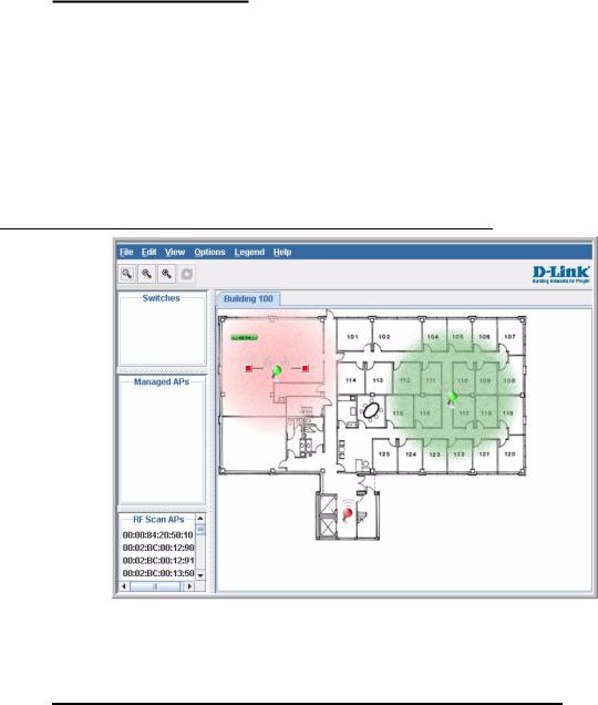
WLAN Visualization
The D-Link Unified Access System includes the WLAN Visualization tool, which provides a graphical representation of your wireless network through a Web browser. WLAN Visualization detects and displays the D-Link Unified Switch, D-Link Access Points, other access points, and all wireless clients associated with the D-Link Access Point. You can import information about your building layout to customize the network view.
Figure 1 shows an example of a floor plan and network with a D-Link Unified Switch that manages two APs. The graph also shows a peer switch and a rogue AP in the network.
Figure 1. Sample WLAN Visualization
The WLAN Visualization tool provides an AP power display with color-coded channels to help you determine where to physically place access points to reduce interference or increase coverage on your WLAN.
D-Link Unified Access System Topology
The WLAN network topology you use depends on the size and requirements of your network. Small-to-medium networks might require only one Unified Switch that manages a few D-Link Access Points. For larger networks that need greater roaming capabilities for wireless clients, a deployment with multiple peer switches that each manage several APs might be appropriate.
D-Link Unified Access System Topology 23
D-Link Unified Access System User Manual
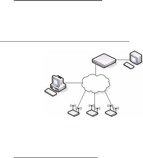
Single Unified Switch Deployment
When you deploy a D-Link Access Point, the D-Link Unified Switch can automatically detect the AP and assign a default profile, which includes automatic RF channel selection and automatic power adjustment. Figure 2 shows a deployment with one D-Link Unified Switch that manages three D-Link Access Points.
Figure 2. Single Unified Switch with Layer 2 Roaming Support
Unified Switch
Terminal with Direct
Serial Connection
L2 Network
Remote Management
Station
AP 1 |
AP 2 |
AP 3 |
When the APs are on the same subnet and have the same SSID, wireless clients can seamlessly roam among the three APs with no interruption in network access. The client keeps the same IP address and does not need to re-authenticate when it moves into the broadcast area of a different AP. Configuration changes to the APs are managed by the switch simultaneously or on a per-AP basis.
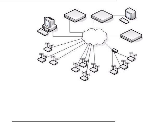
Peer Unified Switch Deployment
To support larger networks, you can configure up to four switches as peers, which increases the size and range of the WLAN. Figure 3 shows a D-Link Unified Access System deployment that utilizes three peer Unified Switches. Each peer Unified Switch can manage
24 © 20012008 D-Link Corporation. All Rights Reserved.
1 Overview of the D-Link Unified Access System
up to 48 access points (DWS-3024 and DWS-3026) or 24 access points (DWS-3024L). The Unified Switch and the APs it manages do not need to be on the same subnet.
Figure 3. Peer Unified Switch with Layer 3 Roaming Support
Unified Switch 1 |
Unified Switch 2 |
Remote Management
Station Terminal with Direct
Serial Connection
L3 Network
Unified Switch 3
Access Points
Managed by Unified Switch 1 Access Points
Managed by Unified Switch 3
Access Points
Managed by Unified Switch 2
Peer Unified Switches share information about APs and allow Layer 3 roaming among them. To support this, peer Unified Switches establish IPv4 tunnels so that the wireless client keeps the same IP address even when the client associates with an access point in a different subnet. The Layer 3 roaming service allows wireless phone users to roam between access points connected to different subnets without dropping calls.
Understanding the User Interfaces
The D-Link Unified Access System enables centralized management of multiple wireless access points, which not only facilitates deployment and management, but also enhances security. The D-Link Unified Access System includes a set of comprehensive management functions for managing and monitoring the WLAN by using one of the following three methods:
•Web-based
•Command-Line Interface (CLI)
•Simple Network Management Protocol (SNMP)
Each of the standards-based management methods enables you to configure, manage, and control the components of the D-Link Unified Access System locally or remotely. Management is standards-based, with configuration parameters and a private MIB that provides control for functions not completely specified in the standard MIBs.
The method you use to configure and monitor the D-Link Unified Switch depends on your network size and requirements, and on your preference.
Understanding the User Interfaces 25
D-Link Unified Access System User Manual
Using the Web Interface
The following Web browsers are supported for Web interface access to the switch:
•Microsoft® Windows® Internet Explorer 6.0
•Microsoft® Windows® Internet Explorer 7.0
Use the following procedures to log on to the Web Interface:
1.Open a Web browser and enter the IP address of the switch in the Web browser address field.
2.Enter the user name and password into the dialogue box that appears.
The user name and password are the same as those you use to log on to the command-line interface. By default, the user name is admin, and there is no password.
3.After the system authenticates you, the System Description page displays.
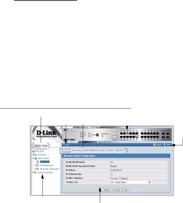
Figure 4 shows the layout of the D-Link Unified Switch Web interface. Each Web page contains three main areas: interface configuration graphic, the navigation tree, and the configuration status or options.
Figure 4. Web Interface Layout
LAN and WLAN Tabs |
Interface Configuration Graphic |
||
Tools Menu |
|||
WLAN Tabs |
|
||
|
|||
|
|
||
|
|
|
|
Help Page
Access
Navigation Tree
Configuration Status and Options
Interface Configuration Graphic
The interface configuration graphic is a Java™ applet that displays the ports on the D-Link Unified Switch. This graphic appears at the top of each page to provide an alternate way to navigate to configuration and monitoring options.
26 © 20012008 D-Link Corporation. All Rights Reserved.
1 Overview of the D-Link Unified Access System
Click the port you want to view or configure to see a menu that displays statistics and configuration options. Click the menu option to access the page that contains the configuration or monitoring options. Click Logout to log out of the Web Interface. From the Logout prompt, click Ok to save your changes and make the changes permanent. Click Cancel to close the Web Interface without saving your changes.
If you click the graphic but do not click a specific port, the main menu appears. This menu contains the same option as the navigation menu on the left side of the page.
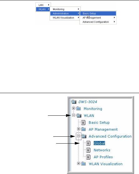
Figure 5. Cascading Navigation Menu
Navigation Menu
A hierarchical-tree view appears to the left of the panel. The tree consists of a combination of folders, subfolders, and configuration and status HTML pages. Click the folder to view the options in that folder. Each folder contains either subfolders or HTML pages, or a combination of both. Figure 6 shows an example of a folder, subfolder, and HTML page in the navigation menu. When you click a folder or subfolder that is preceded by a plus (+), the folder expands to display the contents. If you click an HTML page, a new page displays in the main frame. A folder or subfolder has no corresponding HTML page.
Figure 6. Hierarchical Tree Navigation Menu
Folder
Subfolder
HTML Page
Configuration and Monitoring Options
The panel directly under the graphic and to the right of the navigation menu displays the configuration information or status for the page you select. On pages that contain configuration options, you can input information into fields or select options from drop-down menus.
Understanding the User Interfaces 27

D-Link Unified Access System User Manual
Each page contains access to the HTML-based Help that explains the fields and configuration options for the page. Many pages also contain command buttons.
The following command buttons are used throughout the pages in the Web interface:
Submit |
Clicking the Submit button sends the updated configuration to the switch. |
|
Configuration changes take effect immediately, but some changes are not |
|
retained across a power cycle unless you save them to the system configura- |
|
tion file. |
Save |
Clicking the Save button saves the current configuration to the system config- |
|
uration file. When you click Save, changes that you have submitted are saved |
|
even when you reboot the system. To save the configuration, use the Save |
|
Changes link in the Tools menu. |
Refresh |
Clicking the Refresh button refreshes the data on the panel. |
WLAN Tabs
Many of the pages in the WLAN folder contain tabs to simplify navigation and to group functions for a common feature. Click the tab to access a specific page.
NOTE: Other packages in the software suite do not use tabs in the Web interface.
Tools Menu
If you mouse over the Tool icon, a list of the following useful system tools appears:
•Reset Configuration
•Reset Password
•Reboot System
•Save Changes
•Download File
•Upload File
•Multiple Image Services
Each item in the list is a link to the Web page where you can perform the related task.
Using the Command-Line Interface
The command-line interface (CLI) is a text-based way to manage and monitor the system. You can access the CLI by using a direct serial connection or by using a remote logical connection with Telnet or SSH.
The CLI groups commands into modes according to the command function. Each of the command modes supports specific commands. The commands in one mode are not available until you switch to that particular mode, with the exception of the User EXEC mode commands. You can execute the User EXEC mode commands in the Privileged EXEC mode.
To display the commands available in the current mode, enter a question mark (?) at the command prompt. To display the available command keywords or parameters, enter a question mark (?) after each word you type at the command prompt. If there are no additional command
28 © 20012008 D-Link Corporation. All Rights Reserved.

1 Overview of the D-Link Unified Access System
keywords or parameters, or if additional parameters are optional, the following message appears in the output:
<cr> |
Press Enter to execute the command |
For more information about the CLI, see the D-Link CLI Command Reference.
The D-Link CLI Command Reference lists each command available from the CLI by the command name and provides a brief description of the command. Each command reference also contains the following information:
•The command keywords and the required and optional parameters.
•The command mode you must be in to access the command.
•The default value, if any, of a configurable setting on the device.
The show commands in the document also include a description of the information that the command shows.
Using SNMP
For D-Link Unified Switch software that includes the SNMP module, you can configure SNMP groups and users that can manage traps the SNMP agent generates.
The D-Link Unified Switch uses both standard public MIBs for standard functionality as well as a number of additional private MIBs for additional functionality supported by the switch. All private MIBs begin with a “DLINK-” prefix. The main object for interface configuration is in DLINK-SWITCHING-MIB, which is a private MIB. Some interface configurations also involve objects in the public MIB, IF-MIB.
SNMP is enabled by default. The System Description Web page, which is the page the displays after a successful login, and the show sysinfo command display the information you need to configure an SNMP manager to access the switch.
Any user can connect to the switch using the SNMPv3 protocol, but for authentication and encryption, you need to configure a new user profile. To configure a profile by using the CLI, see the SNMP section in the D-Link CLI Command Reference. To configure an SNMPv3 profile by using the Web interface, use the following steps:
1.Select LAN > Administration > User Accounts from the hierarchical tree on the left side of the Web interface.
2.Using the User pull-down menu, select Create to create a new user.
3.Enter a new user name in the User Name field.
4.Enter a new user password in the Password field and then retype it in the Confirm Password field.
To use SNMPv3 Authentication for this user, set a password of eight or more alphanumeric characters.
5.To enable authentication, use the Authentication Protocol pull-down menu to select either MD5 or SHA for the authentication protocol.
6.To enable encryption, use the Encryption Protocol pull-down menu to select DES for the encryption scheme. Then, enter an encryption code of eight or more alphanumeric characters in the Encryption Key field.
Understanding the User Interfaces 29

D-Link Unified Access System User Manual
7. Click Submit.
To access configuration information for SNMPv1 or SNMPv2, click LAN > Administration > SNMP Manager and click the page that contains the information to configure.
Wireless System Features and Standards Support
In addition to core switching features, the D-Link Unified Switch supports the following features and standards:
•IP Tunneling
•Spanning Tree
•Auto detection and configuration of APs
•Automatic Peer-Switch Discovery
•Automatic or Manual RF Channel Assignment
•Automatic or Manual AP Power Adjustment
•AP Authentication
•Client Authentication
•Load Balancing
•RF Scan and AP Sentry Mode
•Dual Radio Support
•Multiple Mode Support for Radios:
-IEEE 802.11a
-IEEE 802.11b
-IEEE 802.11g
-Dynamic Turbo 5Ghz
-Dynamic Turbo 2.4 Ghz
•IEEE 802.11h (TPC and DFS)
•Security Standard Support:
-WEP (64, 128)
-WEP (152)
-TKIP
-AES & CCMP
-Inhibit SSID broadcast
-WPA (Personal)
-WPA (Enterprise)
-WPA2 (Personal) 802.11i
-WPA2 (Enterprise) 802.11i
•MAC Authentication
•Multiple BSSID/VLANs
•Security and Authentication Settings per SSID
•VLAN Support
•IEEE 802.11d (Country Code)
•IEEE 802.11e (WMM)
•RADIUS support
•WLAN Visualization (NMS like product for APs)
•Mobility
-Interand IntraSubnet Fast Roaming
-Key caching
30 © 20012008 D-Link Corporation. All Rights Reserved.
 Loading...