


DSL-3580L
Table of contents
 Loading...
Table of Content
D-Link DSL-3580L User Manual
1

Table of Content
D-Link DSL-3580L User Manual
2
Table of Contents
PACKAGE CONTENTS .................................................................. 4
SYSTEM REQUIREMENTS ............................................................ 5
INTRODUCTION ............................................................................. 6
FEATURES ..................................................................................... 7
HARDWARE OVERVIEW – CONNECTIONS ................................ 9
INSTALLATION ............................................................................ 11
BEFORE YOU BEGIN ............................................................... 11
Installation Notes ................................................................. 12
Information you need from the Internet service provider . 14
Information you need to know about DSL-3580L .............. 16
Information you will need about your LAN or computer: . 17
Wireless Installation Considerations ................................. 18
DEVICE INSTALLATION .......................................................... 19
Power on Router .................................................................. 19
Factory Reset Button ........................................................... 20
Network Connections .......................................................... 20
CONFIGURATION ........................................................................ 22
WEB-BASED CONFIGURATION UTILITY ............................... 22
SETUP ....................................................................................... 23
INTERNET SETUP ................................................................ 23
WIRELESS SETUP ................................................................ 31
LAN SETUP ........................................................................... 40
TIME AND DATE ................................................................... 42
IPv6 ........................................................................................ 45
USB SETUP ........................................................................... 51
ADVANCED .............................................................................. 55
PORT FORWARDING ............................................................ 56
APPLICATION RULES CONFIGURATION ........................... 57
QOS SETUP .......................................................................... 58
OUTBOUND FILTER ............................................................. 60
INBOUND FILTER ................................................................. 61
WIRELESS FILTER ............................................................... 63
DNS SETUP .......................................................................... 64
FIREWALL & DMZ ................................................................. 66
ADVANCED INTERNET ........................................................ 68
ADVANCED WIRELESS ....................................................... 70
ADVANCED LAN ................................................................... 72
PORT MAPPING ................................................................... 73
SNMP SETUP ....................................................................... 75
PARENTAL CONTROL ......................................................... 76
ROUTING SETUP ................................................................. 77
Wi-Fi PROTECTED SETUP .................................................. 79
IPV6 FIREWALL .................................................................... 80
IPV6 ROUTING ..................................................................... 82
BUDGET QUOTA .................................................................. 83
LOGOUT ............................................................................... 84
MAINTENANCE ........................................................................ 85
PASSWORD .......................................................................... 85
SAVE/RESTORE SETTINGS ................................................ 86
FIRMWARE UPDATE ............................................................ 87
REMOTE MANAGEMENT .................................................... 88
DIAGNOSTICS ...................................................................... 89
PING TEST ............................................................................ 90
SYSTEM LOG ....................................................................... 91
SCHEDULE ........................................................................... 93
STATUS .................................................................................... 94
DEVICE INFO ........................................................................ 94
CONNECTED CLIENTS ........................................................ 97
STATISTICS .......................................................................... 98
ROUTING INFO .................................................................. 100
IPv6 STATUS ....................................................................... 101
IPv6 ROUTING INFO .......................................................... 102

Table of Content
D-Link DSL-3580L User Manual
3
TROUBLESHOOTING ................................................................ 103
APPENDIX .................................................................................. 105
WIRELESS BASICS ............................................................... 105
NETWORKING BASICS ......................................................... 108
CHECK YOUR IP ADDRESS .................................................. 108
STATICALLY ASSIGN AN IP ADDRESS ............................... 109
FCC CAUTION ........................................................................ 110
IC CAUTION ............................................................................ 111
CONTACTING TECHNICAL SUPPORT ................................. 112
D-LINK LINK’N PRINT ............................................................ 113
TECHNICAL SPECIFICATIONS ............................................. 120
Section 1 - Product Overview
D-Link DSL-3580L User Manual
4
Package Contents
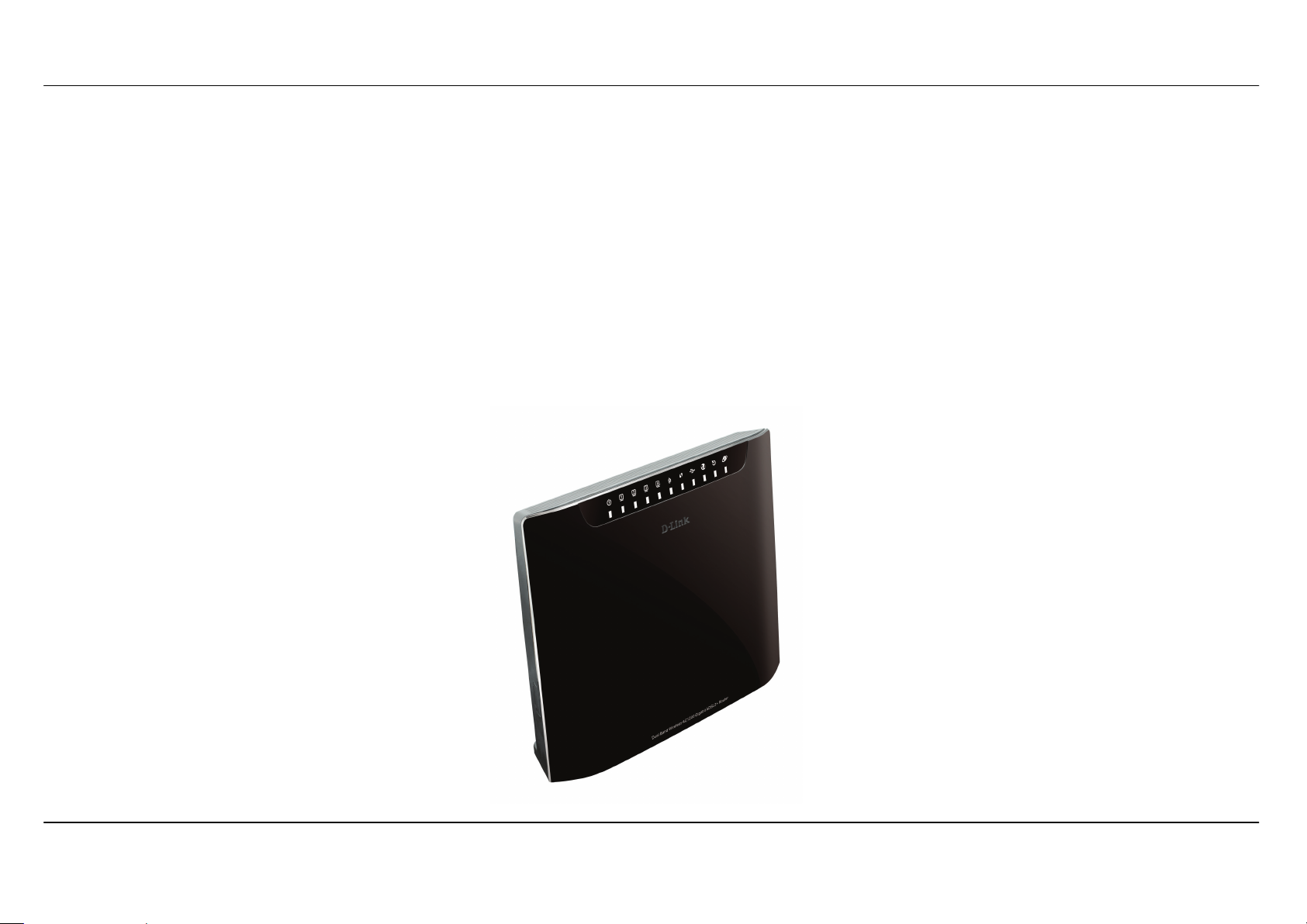
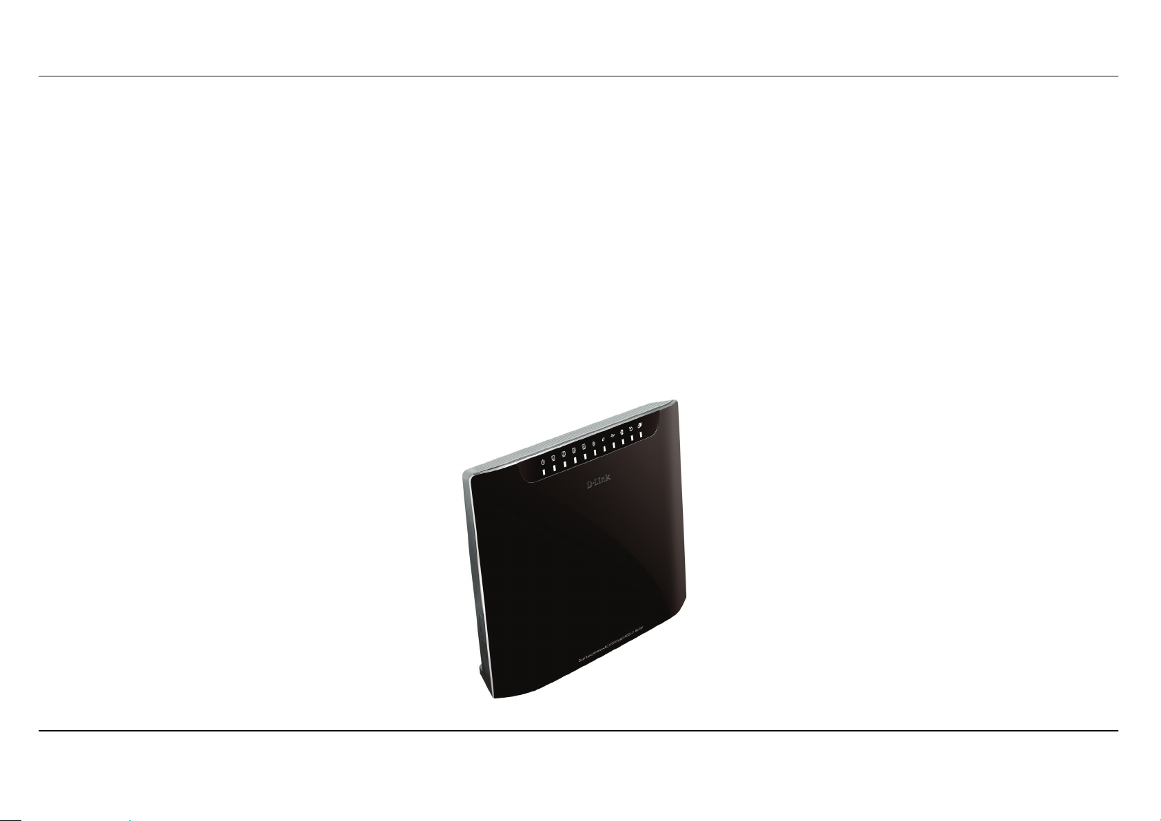
• DSL-3580L Dual Band Wireless AC1200 Gigabit ADSL2+ Router
• 2 Internal Antenas (MIMO 2x2)
• Power Adapter
• CD-ROM with Installation Wizard, User Manual, and Special Offers
• One twisted-pair telephone cable used for ADSL connection
• One straight-through 8P8C RJ-45 Ethernet cable
• One Quick Installation Guide
Note: Using a power supply with a different voltage rating than the one included within the package will cause damage and void the warranty for
this product.
Section 1 - Product Overview
D-Link DSL-3580L User Manual
5
System Requirements
1. ADSL Internet service
Computer with:
• 200MHz Processor
• 64MB Memory
• CD-ROM Drive
• Ethernet Adapter with TCP/IP Protocol Installed
• Windows 8/7/vista/XP/2000z
• MAC OS
• Internet Explorer v6 or later, FireFox v1.5
2. DCC (D-Link Click's Connect) Utility
Computer with:
• MS Windows – Win7/Vista/XP/2000

Section 1 - Product Overview
D-Link DSL-3580L User Manual
6
11
Introduction
HIGH-SPEED WAN (ADSL2/2+ or Gigabit Ethernet WAN) INTERNET CONNECTION
Latest ADSL2/2+ standards provide Internet transmission of up to 24Mbps downstream, 2.7Mbps upstream. Gigabit Ethernet WAN offers you plenty of bandwidth
once you decide to employ Ethernet WAN to connect front end bridge modem.
HIGH-PERFORMANCE WIRELESS
Embedded 802.11ac* technology for high-speed wireless connection, complete compatibility with 802.11b/g/n wireless devices
TOTAL SECURITY
Firewall protection from Internet attacks, user access control, WPA/WPA2 wireless security.
ULTIMATE INTERNET CONNECTION
The DSL-3580L ADSL2+ router is a versatile, high-performance remote router for home and the small office. With integrated ADSL2/2+ supporting up to 24Mbps
download and 2.7Mbps upload speed, Gigabit Ethernet WAN Port, firewall protection, Quality of Service (QoS), 802.11ac wireless LAN and 4 Gigabit Ethernet
LAN switch ports, this router provides all the functions that a home or small office needs to establish a secure and high-speed remote link to the outside world.
ULTIMATE WIRELESS CONNECTION WITH MAXIMUM SECURITY
This router provides maximize wireless performance by connecting this router to computer interfaces and stay connected from virtually anywhere at home and in
the office. The router can be used with 802.11a/b/g/n/ac wireless networks to enable significantly improved reception. It supports WPA/WPA2 and WEP for
flexible user access security and data encryption methods.
FIREWALL PROTECTION & QoS
Security features prevents unauthorized access to the home and office network, be it from the wireless devices or from the Internet. The router provides firewall
security using Stateful Packet Inspection (SPI) and hacker attack logging for Denial of Service (DoS) attack protection. SPI inspects the contents of all incoming
packet headers before deciding what packets are allowed to pass through. Router access control is provided with packet filtering based on port and
source/destination MAC/IP addresses. For Quality of Service (QoS), the router supports multiple priority queues to enable a group of home or office users to
experience the benefit of smooth network connection of inbound and outbound data without concern of traffic congestion. This QoS support allows users to enjoy
high ADSL transmission for applications such as VoIP and streaming multimedia over the Internet.
*Maximum wireless signal rate derived from IEEE standard 802.11ac specifications. Actual data throughput will vary. Network conditions and environmental factors, including volume of network
traffic, building materials and construction, and network overhead, lower actual data throughput rate. Environmental factors will adversely affect wireless signal range.

Section 1 - Product Overview
D-Link DSL-3580L User Manual
7
Features
• Faster Wireless Networking - The DSL-3580L router provides up to 866Mbps* wireless connection with other 802.11ac wireless clients. This capability
allows users to participate in real-time activities online, such as video streaming, online gaming, and real-time audio.
• Compatible with 802.11a, 802.11b, 802.11g, 802.11n and 802.11ac* Devices - The DSL-2880AL series router is still fully compatible with the IEEE 802.11a,
b, g, n and ac standards. Thus it can connect with existing 802.11a, b, g, n and ac* PCI, USB and Card-bus adapters.
• DHCP Support - Dynamic Host Configuration Protocol automatically and dynamically assigns all LAN IP settings to each host on your network. This
eliminates the need to reconfigure every host whenever changes in network topology occur.
• Network Address Translation (NAT) - For small office environments, the DSL-3580L allows multiple users on the LAN to access the Internet concurrently
through a single Internet account. This provides Internet access to everyone in the office for the price of a single user. NAT improves network security in effect
by hiding the private network behind one global and visible IP address. NAT address mapping can also be used to link two IP domains via a LAN-to-LAN
connection.
• Precise ATM Traffic Shaping - Traffic shaping is a method of controlling the flow rate of ATM data cells. This function helps to establish the Quality of
Service for ATM data transfer.
• High Performance WAN - Very high rates of data transfer are possible with the Router. Up to 24Mbps downstream bit rate over DSL interface by using the
G.dmt standard (ADSL2+). Gigabit Ethernet WAN offers you plenty of bandwidth once you decide to employ Ethernet WAN to connect front end bridge
modem with Ethernet LAN port.
• Full Network Management - The DSL-3580L incorporates SNMP (Simple Network Management Protocol) support for web-based management and
text-based network management via Telnet connection.
• Easy Installation - The DSL-3580L uses a web-based graphical user interface program for convenient management access and easy set up. Any common
web browser software can be used to manage the Router.
• USB Support- The DSL-3580L provides USB port for easy sharing files and printers. The DSL-3580L supports USB storage device sharing files through
SAMBA file server, FTP server, Web file server and in addition also supports sharing USB printer server to network members (Remark: The client computers
are required to install additional software utility named D-Link Link’n Print.). Besides sharing function, the DSL-3580L also supports connect to internet by
USB 3G modem.
• IPv6 Connection Support – For IPv6 connection, the DSL-3580L provides several connection type: Link-local, Static IPv6, DHCPv6, Stateless
Auto-configuration, PPPoE, IPv6 in IPv4 Tunnel and 6to4.

Section 1 - Product Overview
D-Link DSL-3580L User Manual
8
*Maximum wireless signal rate derived from IEEE standard 802.11ac specifications. Actual data throughput will vary. Network conditions and environmental factors, including volume of network
traffic, building materials and construction, and network overhead, lower actual data throughput rate. Environmental factors will adversely affect wireless signal range.
Section 1 - Product Overview
D-Link DSL-3580L User Manual
9
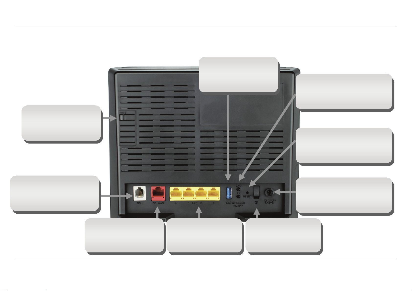
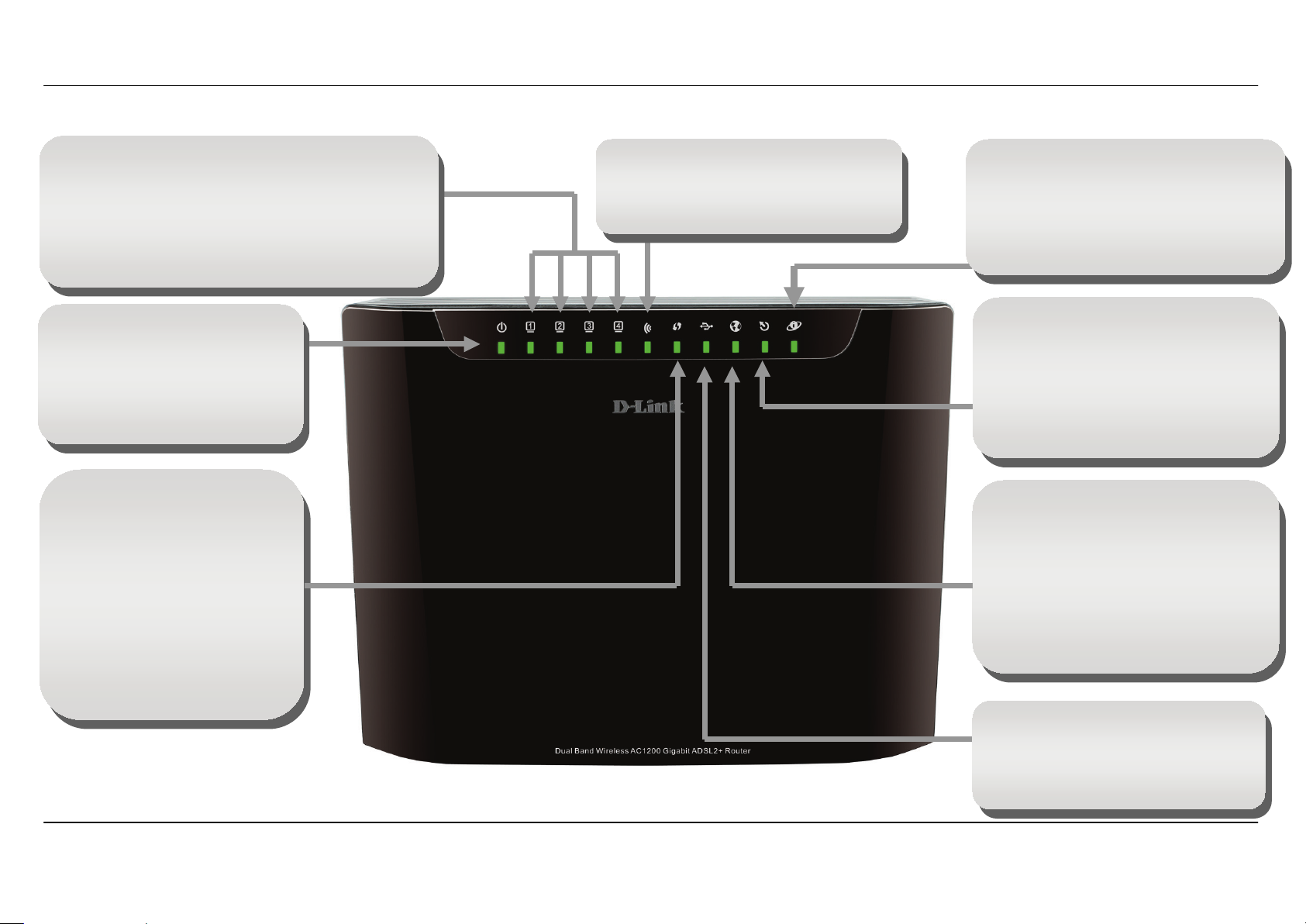
Hardware Overview – Connections
Power insert
Use the adapter shipped with the
Router to connect to power
source
Power button
Push in to power-on the
Router. Push again to
power-off the Router
ADSL port
Use the ADSL cable to
connect to the your telephone
line (RJ-11 port)
Reset button
To manually reset, depress
button with the power on for
between ten and fifteen seconds
2.4G & 5G Wireless On/Off
switch button
Please press and hold on for 3
seconds to turn on/turn off.
USB port
Use the USB port to
connect your USB device.
Giga Ethernet ports
To connect the Router to
your Ethernet LAN or
Ethernet devices
Giga Ethernet WAN port
To connect the Router to
front end Bridge Modem
device Ethernet LAN
WPS H/W Push button
To pair-up the wireless
device which also support
WPS feature
Section 1 - Product Overview
D-Link DSL-3580L User Manual
10
Hardware Overview – LED Indication
Power
Steady Green light indicates the
unit is powered on. When the
device is powered off this
remains dark.
DSL
Steady Green light indicates a valid
ADSL connection. This will light after
the ADSL negotiation process has
been settled. A blinking Green light
indicates activity on the WAN (ADSL)
interface.
Ethernet LAN
A solid Green light indicates a valid link on startup at
1000Mbps. A solid Yellow light indicates a valid link
on startup at 100Mbps. A solid Green + Yellow light
indicates link rate is 10Mbps.These lights blink when
there is activity currently passing through the
Ethernet port.
WLAN
Steady green light indicates a wireless
connection. A blinking green light
indicates activity on the WLAN interface
Internet
Steady Green light indicates a successful
Internet connection. Steady Red light
indicates failed Internet connection. Dark
if no WAN protocol is configured.
USB
Steady Green light indicates a
successful USB connection. Dark if no
USB device is plugged.
Ethernet WAN
A solid Green light indicates a valid link
on startup at 1000Mbps. A solid Yellow
light indicates a valid link on startup at
100Mbps. A solid Green + Yellow light
indicates link rate is 10Mbps.This light
blinks when there is activity currently
passing through the Ethernet port.
WPS
Dark indicates ready for new
WPS connection. Blinking
indicates WPS process is
triggered and waiting for
another WPS device joining.
Steady Blue light indicates
connection is successfully
established between the router
and the client. The LED will
remain in solid Blue for 5
seconds.

Section 2 - Installation
D-Link DSL-3580L User Manual
11
Installation
This section will walk you through the installation process. Placement of the router is very important. Do not place the router in an enclosed area
such as a closet, cabinet, or in the attic or garage.
Before you Begin
Please read and make sure you understand all the prerequisites for proper installation of your new Router. Have all the necessary information and
equipment on hand before beginning the installation.

Section 2 - Installation
D-Link DSL-3580L User Manual
12
Installation Notes
In order to establish a connection to the Internet it will be necessary to provide information to the Router that will be stored in its memory. For some
users, only their account information (Username and Password) is required. For others, various parameters that control and define the Internet
connection will be required. You can print out the two pages below and use the tables to list this information. This way you have a hard copy of all
the information needed to setup the Router. If it is necessary to reconfigure the device, all the necessary information can be easily accessed. Be
sure to keep this information safe and private.
Low Pass Filters
Since ADSL and telephone services share the same copper wiring to carry their respective signals, a filtering mechanism may be necessary to
avoid mutual interference. A low pass filter device can be installed for each telephone that shares the line with the ADSL line. These filters are easy
to install passive devices that connect to the ADSL device and/or telephone using standard telephone cable. Ask your service provider for more
information about the use of low pass filters with your installation.
Operating Systems
The DSL-3580L uses an HTML-based web interface for setup and management. The web configuration manager may be accessed using any
operating system capable of running web browser software, including Windows 98 SE, Windows ME, Windows 2000, and Windows XP, Windows 7,
Windows 8.
Web Browser
Any common web browser can be used to configure the Router using the web configuration management software. The program is designed to
work best with more recently released browsers such as Opera, Microsoft Internet Explorer® version 6.0, Netscape Navigator® version 6.2.3, or
later versions. The web browser must have JavaScript enabled. JavaScript is enabled by default on many browsers. Make sure JavaScript has not
been disabled by other software (such as virus protection or web user security packages) that may be running on your computer.
Ethernet Port (NIC Adapter)
Any computer that uses the Router must be able to connect to it through the Ethernet port on the Router. This connection is an Ethernet connection
and therefore requires that your computer be equipped with an Ethernet port as well. Most notebook computers are now sold with an Ethernet port
already installed. Likewise, most fully assembled desktop computers come with an Ethernet NIC adapter as standard equipment. If your computer
does not have an Ethernet port, you must install an Ethernet NIC adapter before you can use the Router. If you must install an adapter, follow the
installation instructions that come with the Ethernet NIC adapter.

Section 2 - Installation
D-Link DSL-3580L User Manual
13
802.11 Wireless LAN Configuration
All the 802.11 wireless LAN settings may be configured on a single page using the web-based manager. For basic wireless communication you
need to decide what channel to use and what SSID to assign. These two settings must be the same for any wireless workstations or other wireless
access point that communicate with the DSL-3580L through the wireless interface.
Security for wireless communication can be accomplished in a number of ways. DSL-3580L supports WPA (Wi-Fi Protected Access), WPA2, and
mixed WPA/WPA2. Wireless access can also be controlled by selecting MAC addresses that are allowed to associate with the device. Please read
the section on Wireless Configuration.
Additional Software
It may be necessary to install software on your computer that enables the computer to access the Internet. Additional software must be installed if
you are using the device a simple bridge. For a bridged connection, the information needed to make and maintain the Internet connection is stored
on another computer or gateway device, not in the Router itself.
If your ADSL service is delivered through a PPPoE or PPPoA connection, the information needed to establish and maintain the Internet connection
can be stored in the Router. In this case, it is not necessary to install software on your computer. It may however be necessary to change some
settings in the device, including account information used to identify and verify the connection.
All connections to the Internet require a unique global IP address. For bridged connections, the global IP settings must reside in a TCP/IP enabled
device on the LAN side of the bridge, such as a PC, a server, a gateway device such as a router or similar firewall hardware. The IP address can be
assigned in a number of ways. Your network service provider will give you instructions about any additional connection software or NIC
configuration that may be required.

Section 2 - Installation
D-Link DSL-3580L User Manual
14
Information you need from the Internet service
provider
Username
This is the Username used to log on to your ADSL service provider’s network. It is commonly in the form user@isp.co.uk. Your ADSL service
provider uses this to identify your account.
Password
This is the Password used, in conjunction with the Username above, to log on to your ADSL service provider’s network. This is used to verify the
identity of your account.
WAN Setting / WAN Media Typ e / Connection Type
These settings describe the method your Internet service provider uses to transport data between the Internet and your computer. Most users will
use the default settings. You may need to specify one of the following WAN Setting and Connection Type configurations (Connection Type settings
listed in parenthesis):
• WAN Media Type (RJ-11 for DSL digital subscriber line or RJ-45 Ethernet for connecting your device to a VDSL bridge modem or a optical
network unit, also known as ONU)
• PPPoE / PPPoA (PPPoE LLC, PPPoA LLC or PPPoA VC-Mux)
• Bridge Mode (1483 Bridged IP LLC or 1483 Bridged IP VC Mux)
• IPoA / MER (Static IP Address) (Bridged IP LLC, 1483 Bridged IP VC Mux, 1483 Routed IP LLC, 1483 Routed IP VC-Mux or IPoA)
• MER (Dynamic IP Address) (1483 Bridged IP LLC or 1483 Bridged IP VC-Mux)
Modulation Type
ADSL uses various standardized modulation techniques to transmit data over the allotted signal frequencies. Some users may need to change the
type of modulation used for their service. The default DSL modulation (ADSL2+ Multi-Mode) used for the Router automatically detects all types of
ADSL, ADSL2, and ADSL2+ modulation. However, if you are instructed to specify the modulation type used for the Router, you may choose among
the numerous options available on the Modulation Type drop-down menu on the ADSL Configuration window (Advanced > ADSL)
Security Protocol
This is the method your ADSL service provider will use to verify your Username and Password when you log on to their network. Your Router
supports the PAP and CHAP protocols.

Section 2 - Installation
D-Link DSL-3580L User Manual
15
VPI
Most users will not be required to change this setting. The Virtual Path Identifier (VPI) is used in conjunction with the Virtual Channel Identifier (VCI)
to identify the data path between your ADSL service provider’s network and your computer. If you are setting up the Router for multiple virtual
connections, you will need to configure the VPI and VCI as instructed by your ADSL service provider for the additional connections. This setting can
be changed in the WAN Settings window of the web management interface.
VCI
Most users will not be required to change this setting. The Virtual Channel Identifier (VCI) used in conjunction with the VPI to identify the data path
between your ADSL service provider’s network and your computer. If you are setting up the Router for multiple virtual connections, you will need to
configure the VPI and VCI as instructed by your ADSL service provider for the additional connections. This setting can be changed in the WAN
Settings window of the web management interface.

Section 2 - Installation
D-Link DSL-3580L User Manual
16
Information you need to know about DSL-3580L
System Administrator Username
This is the Username needed access the Router’s management interface. When you attempt to connect to the device through a web browser you
will be prompted to enter this Username. The default Username for the Router is “admin.” The user cannot change this.
System Administrator Password
This is the Password you will be prompted to enter when you access the Router’s management interface. The default Password is “admin.” The
user may change this.
LAN IP addresses for the DSL-3580L
This is the IP address you will enter into the Address field of your web browser to access the Router’s configuration graphical user interface (GUI)
using a web browser. The default IP address is 192.168.1.1. This may be changed to suit any IP address scheme the user desires. This address will
be the base IP address used for DHCP service on the LAN when DHCP is enabled.
LAN Subnet Mask for the DSL-3580L
This is the subnet mask used by the DSL-3580L, and will be used throughout your LAN. The default subnet mask is 255.255.255.0. This can be
changed later.

Section 2 - Installation
D-Link DSL-3580L User Manual
17
Information you will need about your LAN or computer:
Ethernet NIC
If your computer has an Ethernet NIC, you can connect the DSL-3580L to this Ethernet port using an Ethernet cable. You can also use the Ethernet
ports on the DSL-3580L to connect to other computer or Ethernet devices.
DHCP Client Status
Your DSL-3580L ADSL Router is configured, by default, to be a DHCP server. This means that it can assign an IP address, subnet mask, and a
default gateway address to computers on your LAN. The default range of IP addresses the DSL-3580L will assign are from 192.168.1.2 to
192.168.1.254. Your computer (or computers) needs to be configured to Obtain an IP address automatically (that is, they need to be configured as
DHCP clients.)
It is recommended that your collect and record this information here, or in some other secure place, in case you have to re-configure your ADSL
connection in the future.
Once you have the above information, you are ready to setup and configure your DSL-3580L Wireless ADSL Router.

Section 2 - Installation
D-Link DSL-3580L User Manual
18
Wireless Installation Considerations
DSL-3580L lets you access your network using a wireless connection from virtually anywhere within the operating range of your wireless network.
Keep in mind, however, that the number, thickness and location of walls, ceilings, or other objects that the wireless signals must pass through, may
limit the range. Typical ranges vary depending on the types of materials and background RF (radio frequency) noise in your home or business. The
key to maximizing wireless range is to follow these basic guidelines:
1. Keep the number of walls and ceilings between the D-Link router and other network devices to a minimum - each wall or ceiling can reduce your
adapter’s range from 3-90 feet (1-30 meters.) Position your devices so that the number of walls or ceilings is minimized.
2. Be aware of the direct line between network devices. A wall that is 1.5 feet thick (.5 meters), at a 45-degree angle appears to be almost 3 feet (1
meter) thick. At a 2-degree angle it looks over 42 feet (14 meters) thick! Position devices so that the signal will travel straight through a wall or
ceiling (instead of at an angle) for better reception.
3. Building Materials make a difference. A solid metal door or aluminum studs may have a negative effect on range. Try to position access points,
wireless routers, and computers so that the signal passes through drywall or open doorways. Materials and objects such as glass, steel, metal,
walls with insulation, water (fish tanks), mirrors, file cabinets, brick, and concrete will degrade your wireless signal.
4. Keep your product away (at least 3-6 feet or 1-2 meters) from electrical devices or appliances that generate RF noise.
5. If you are using 2.4GHz cordless phones or X-10 (wireless products such as ceiling fans, lights, and home security systems), your wireless
connection may degrade dramatically or drop completely. Make sure your 2.4GHz phone base is as far away from your wireless devices as
possible. The base transmits a signal even if the phone in not in use.

Section 2 - Installation
D-Link DSL-3580L User Manual
19
Device Installation
DSL-3580L Daul Band 802.11ac Wireless ADSL2+ Gigabit Ethernet Router maintains four separate interfaces, an Ethernet LAN, a wireless LAN,
an Ethernet WAN and an ADSL Internet (WAN) connection. Carefully consider the Router’s location suitable for connectivity for your Ethernet and
wireless devices. You must have a functioning broadband connection via a bridge device such as a Cable or ADSL modem in order to use the
Router’s WAN function.
Place the Router in a location where it can be connected to the various devices as well as to a power source. The Router should not be located
where it will be exposed to moisture, direct sunlight or excessive heat. Make sure the cables and power cord are placed safely out of the way so
they do not create a tripping hazard. As with any electrical appliance, observe common sense safety procedures.
The Router can be placed on a shelf, desktop, or other stable platform. If possible, you should be able to see the LED indicators on the front if you
need to view them for troubleshooting.
Power on Router
The Router must be used with the power adapter included with the device.
1. Insert the AC Power Adapter cord into the power receptacle located on the rear panel of the Router and plug the adapter into a suitable nearby
power source.
2. Push down the Power button, and you should see the Power LED indicator light up and remain lit.
3. If the Ethernet port is connected to a working device, check the Ethernet Link/Act LED indicators to make sure the connection is valid. The
Router will attempt to establish the ADSL connection, if the ADSL line is connected and the Router is properly configured this should light up
after several seconds. If this is the first time installing the device, some settings may need to be changed before the Router can establish a
connection.

Section 2 - Installation
D-Link DSL-3580L User Manual
20
Factory Reset Button
The Router may be reset to the original factory default settings by using a ballpoint or paperclip to gently push down the reset button in the following
sequence:
1. Press and hold the reset button (the button just beside power button) while the device is powered off.
2. Turn on the power.
3. Wait for 10~15 seconds and then release the reset button.
4. To power off and power on again to make device boot-up in normal state
Remember that this will wipe out any settings stored in flash memory including user account information and LAN IP settings. The device settings
will be restored to the factory default IP address 192.168.1.1 and the subnet mask is 255.255.255.0, the default management Username is “admin”
and the default Password is “admin.”
Network Connections
Connect to ADSL Line
Use the ADSL cable included with the Router to connect it to a telephone wall socket or receptacle. Plug one end of the cable into the ADSL port
(RJ-11 receptacle) on the rear panel of the Router and insert the other end into the RJ-11 wall socket. If you are using a low pass filter device, follow
the instructions included with the device or given to you by your service provider. The ADSL connection represents the WAN interface, the
connection to the Internet. It is the physical link to the service provider’s network backbone and ultimately to the Internet.
Connect Router to Ethernet
The Router may be connected to a single computer or Ethernet device through the 10BASE-TX Ethernet port on the rear panel. Any connection to
an Ethernet concentrating device such as a switch or hub must operate at a speed of 10/100/1000 Mbps only. When connecting the Router to any
Ethernet device that is capable of operating at speeds higher than 10Mbps, be sure that the device has auto-negotiation (NWay) enabled for the
connecting port. Use standard twisted-pair cable with RJ-45 connectors. The RJ-45 port on the Router is a crossed port (MDI-X). Follow standard
Ethernet guidelines when deciding what type of cable to use to make this connection. When connecting the Router directly to a PC or server use a
normal straight-through cable. You should use a crossed cable when connecting the Router to a normal (MDI-X) port on a switch or hub. Use a
normal straight-through cable when connecting it to an uplink (MDI-II) port on a hub or switch. The rules governing Ethernet cable lengths apply to
the LAN to Router connection. Be sure that the cable connecting the LAN to the Router does not exceed 100 meters.
Section 2 - Installation
D-Link DSL-3580L User Manual
21
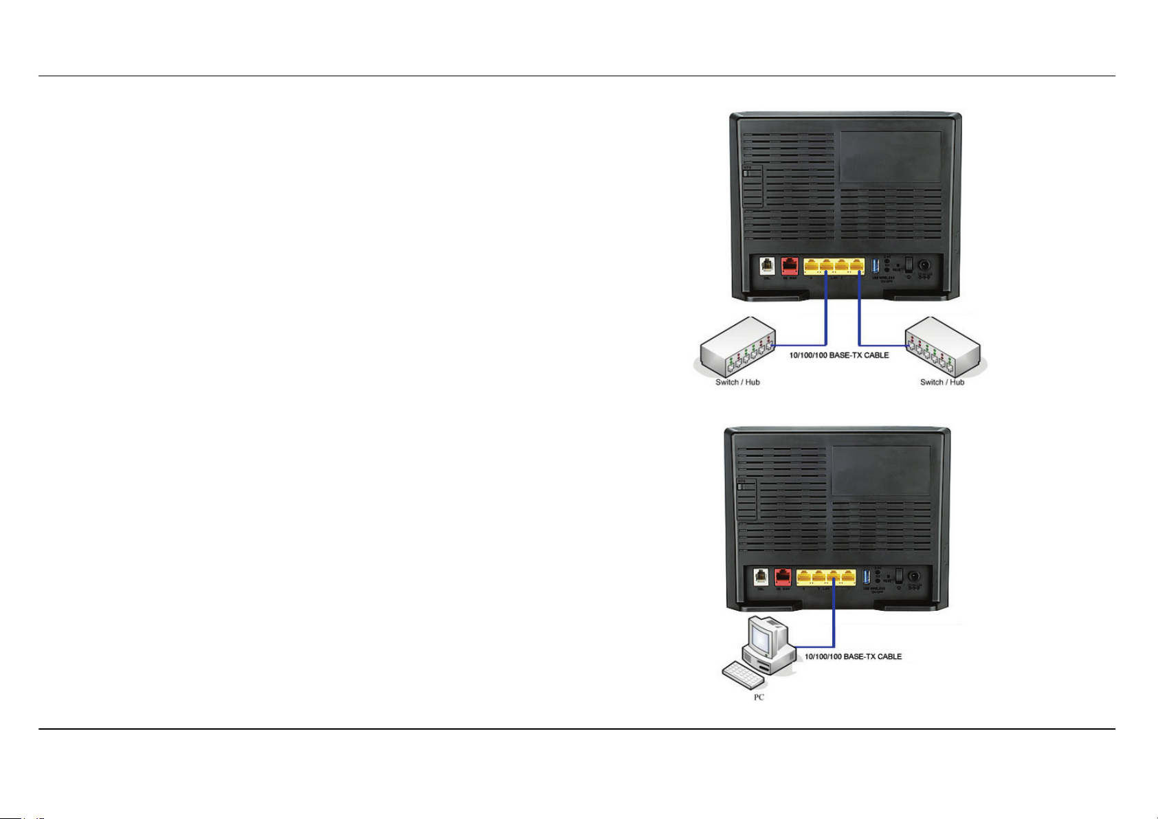
Hub or Switch to Router Connection
Connect the Router to an uplink port (MDI-II) on an Ethernet hub or switch
with a straight-through 8P8C RJ-45 Ethernet cable as shown in this diagram.
If you wish to reserve the uplink port on the switch or hub for another device,
connect to any on the other MDI-X ports (1x, 2x, etc.) with a crossed cable.
Computer to Router Connection
You can connect the Router directly to a 10/100/1000 BASE-TX Ethernet
adapter card (NIC) installed on a PC using the straight-through 8P8C RJ-45
Ethernet cable provided as shown in this diagram.
Section 3 - Configuration
D-Link DSL-3580L User Manual
22
Configuration
This section will show you how to configure your new D-Link wireless router using the web-based configuration utility.
Web-based Configuration Utility
Connect to the Router
To configure the WAN connection used by the Router it is first necessary to communicate with the Router through its management interface, which
is HTML-based and can be accessed using a web browser. The easiest way to make sure your computer has the correct IP settings is to configure
it to use the DHCP server in the Router. The next section describes how to change the IP configuration for a computer running a Windows operating
system to be a DHCP client.
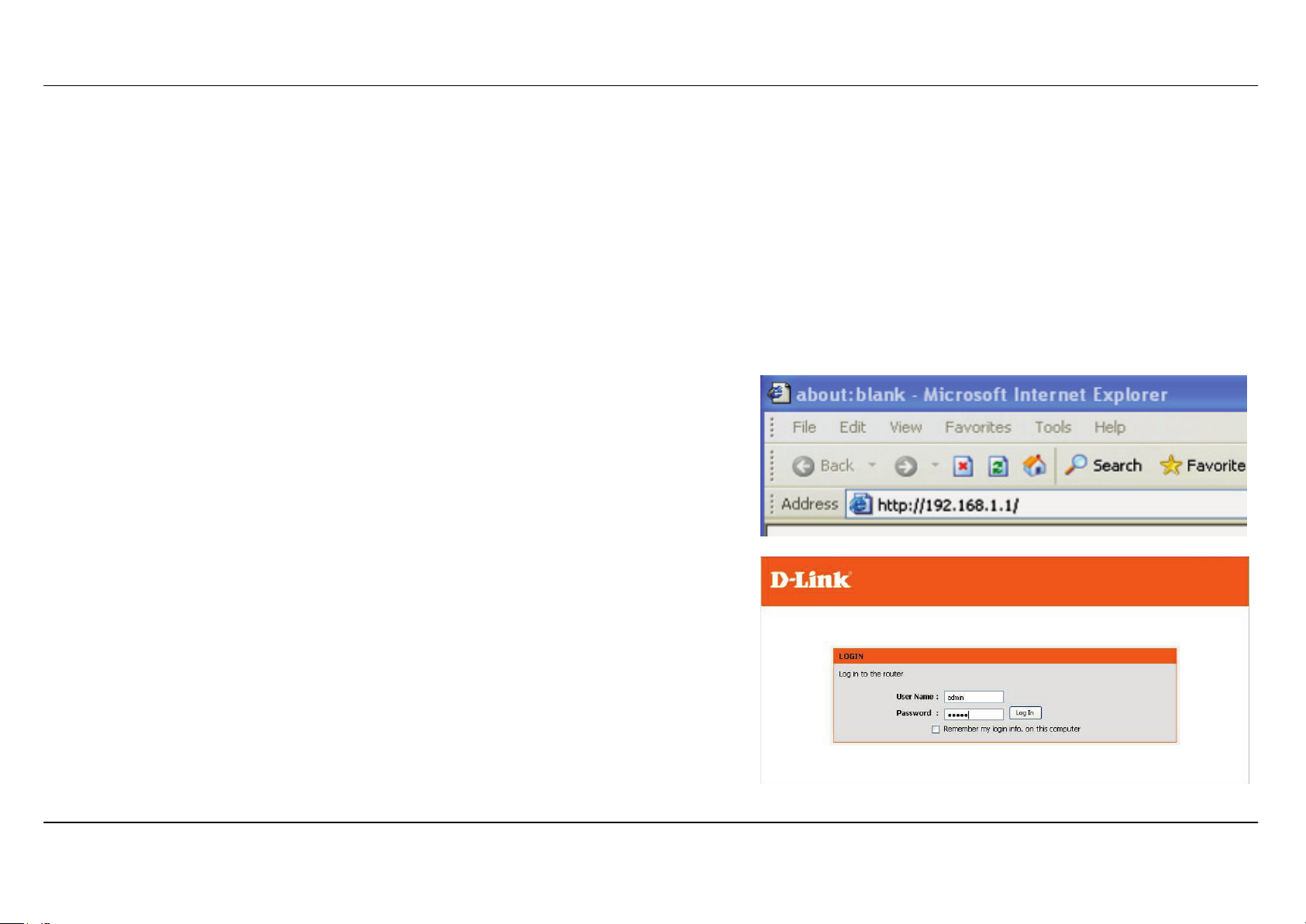
To access the configuration utility, open a web-browser such as Internet Explorer and
enter the IP address of the router (192.168.1.1).
Type “admin” for the User Name and “admin” in the Password field. If you get a
Page Cannot be Displayed error, please refer to the Troubleshooting section for
assistance.
Section 3 - Configuration
D-Link DSL-3580L User Manual
23
SETUP
This chapter is concerned with using your computer to configure the WAN connection. The following chapter describes the various windows used to
configure and monitor the Router including how to change IP settings and DHCP server setup.
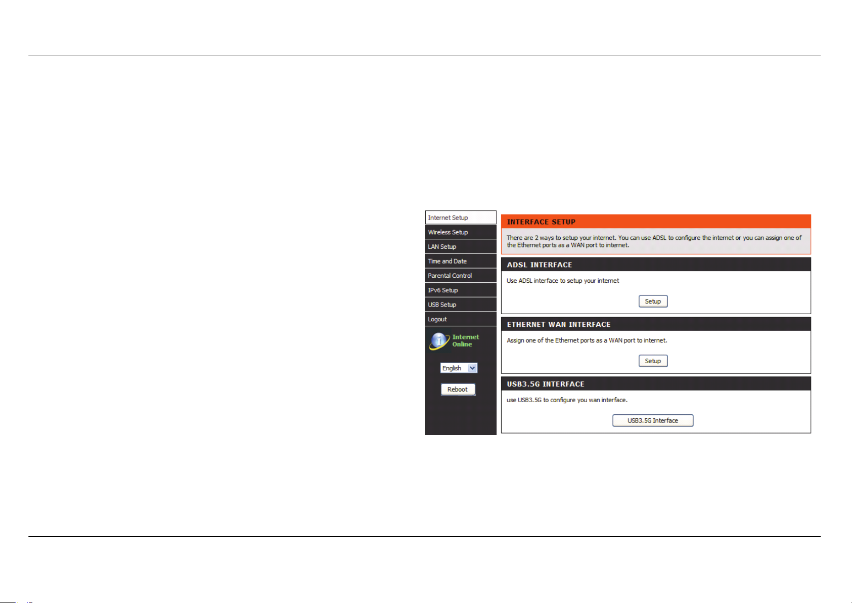
INTERNET SETUP
To access the INTERNET SETUP (WAN) settings window, click on the Internet Setup button in the SETUP directory in this page:
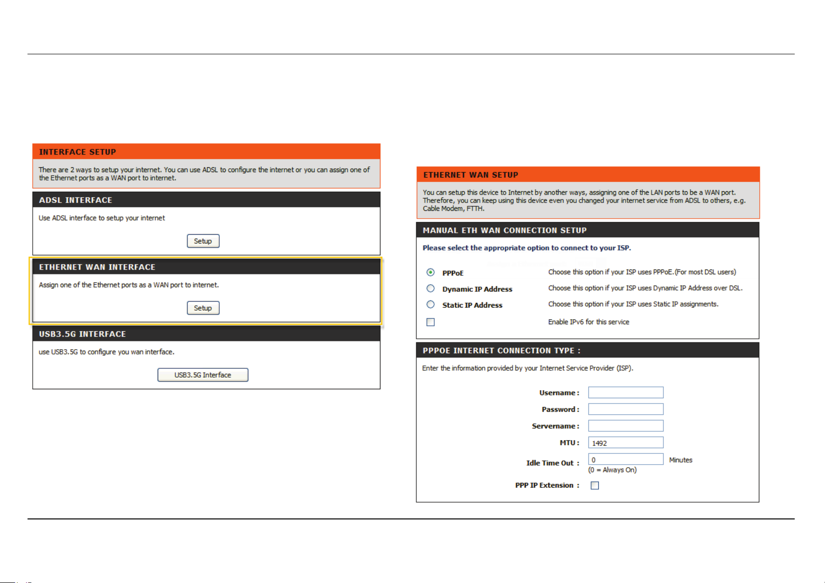
INTERFACE SETUP:
ADSL INTERFACE
Click on the Setup button located over ADSL INTERFACE if you want to
configure ADSL Interface WAN.
ETH INTERFACE
Click on the Setup button located over ETHERNET WAN INTERFACE if
you want to configure Ethernet WAN.
Section 3 - Configuration
D-Link DSL-3580L User Manual
24
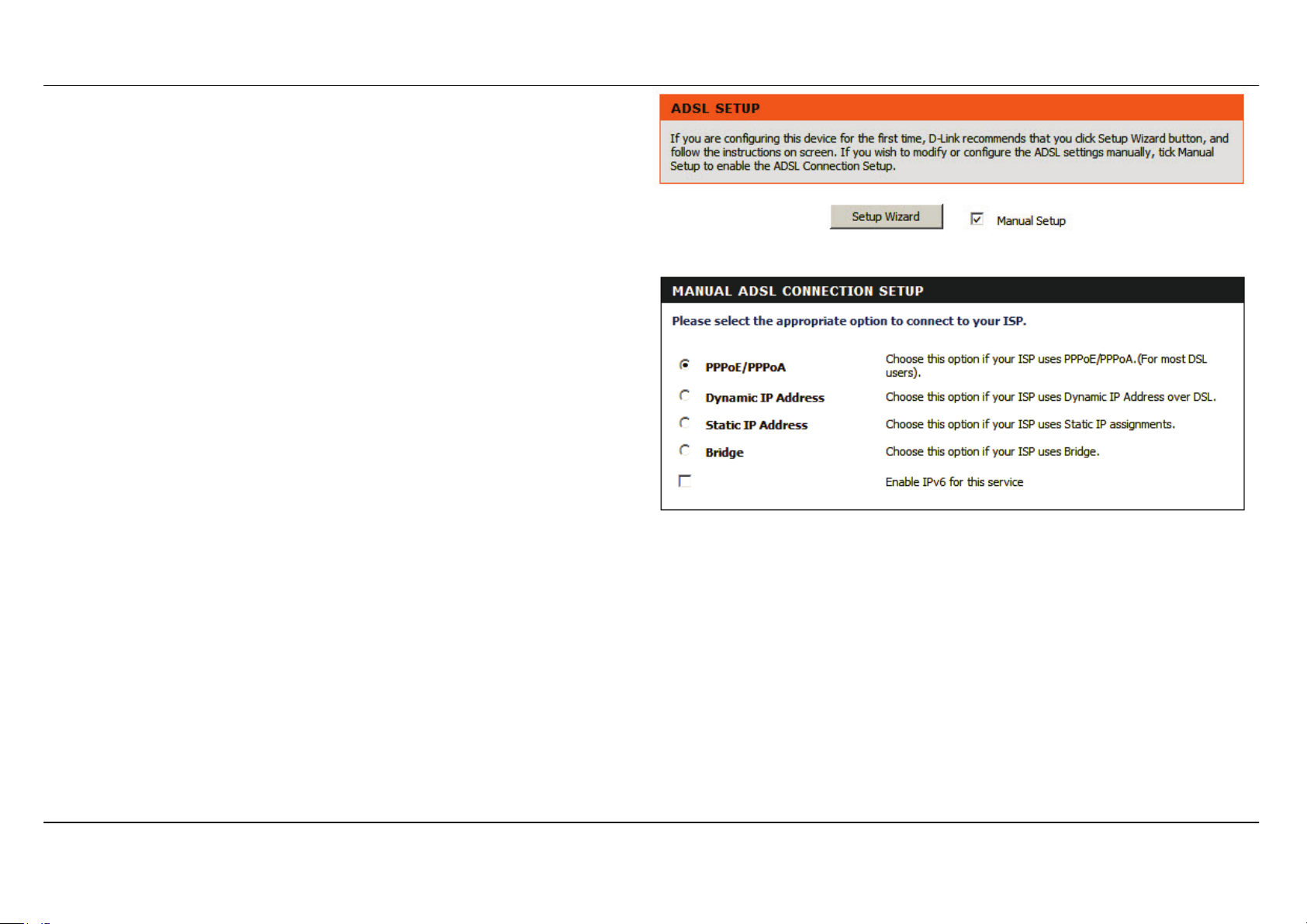
ADSL WAN SETUP
Check Manual Setup box to configuring Internet connection manually or
you can click on Setup Wizard button to configuring router step-by-step.
MANUAL ADSL CONNECTION SETUP
Please select the connection type for your internet connection.
If your Internet service supported IPv6, you can click Enable IPv6 for
this service to setup IPv6 in this connection
Section 3 - Configuration
D-Link DSL-3580L User Manual
25
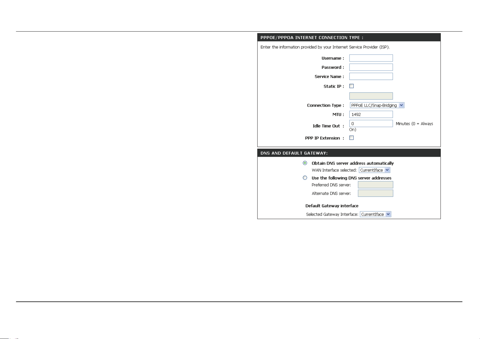
For PPPoE/PPPoA INTERNET CONNECTION TYPE:
Type in the Username and Password (and PPPoE Service Name, if
required by your ISP).
Choose PPPoE LLC/Snap-Bridging, PPPoE VC-mux, PPPoA
LLC/encapsulation and PPPoA VC-mux in drop-down menu.
You can use Static IPv4 Address check box and type Static IP.
Set MTU value which you want but should be less than 1492.
PPP IP Extension: Router passes the obtained IP address to the local
PC and acts as a bridge only modem.
DNS AND DEFAULT GATEWAY
Select Obtain DNS server address automatically to get DNS from
your ISP.
Or Select Use the following DNS server addresses to specify the
DNS server IPs in the Preferred DNS server and
Alternate DNS
server.
Section 3 - Configuration
D-Link DSL-3580L User Manual
26
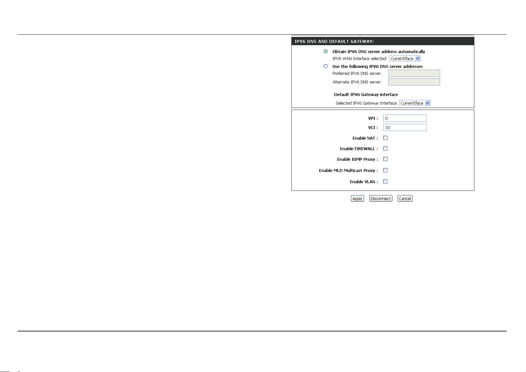
IPv6 DNS AND DEFAULT GATEWAY
Select Obtain IPv6 DNS server address automatically to get DNS
from your ISP.
Or Select Use the following IPv6 DNS server addresses to type the
DNS IPs in the Preferred DNS server and Alternate DNS server.
Select Default IPv6 Gateway Interface in drop-down menu
Set VPI/VCI, enable the Enable NAT
Enable the Enable Firewall when you want to have the basic filter
function, for example, ICMP ping to DSL-3580L.
Enable the Enable IGMP Multicast Proxy to send IGMP query packets
to the IPTV clients.
Enable VLAN and type the VLAN ID (0-4095) which your ISP assigns.
Click on the Apply button to apply setting.
Section 3 - Configuration
D-Link DSL-3580L User Manual
27
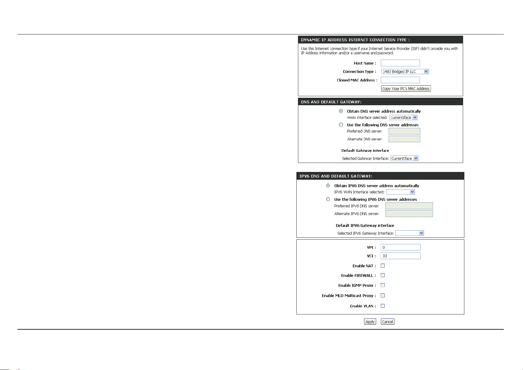
For DYNAMIC IP ADDRESS INTERNET CONNECTION TYPE:
Type Host Name and select Connection Type in drop-down menu
DNS AND DEFAULT GATEWAY
Select Obtain DNS server address automatically to get DNS from
your ISP.
Or Select Use the following DNS server addresses to type the DNS
IP in the Preferred DNS server and Alternate DNS server.
IPv6 DNS AND DEFAULT GATEWAY
Select Obtain IPv6 DNS server address automatically to get DNS
from your ISP.
Or Select Use the following IPv6 DNS server addresses to type the
DNS IPs in the Preferred DNS server and Alternate DNS server.
Select Default IPv6 Gateway Interface in drop-down menu
Set VPI/VCI, enable the Enable NAT.
Enable the Enable Firewall when you want to have the basic filter
function, for example, ICMP ping to DSL-3580L.
Enable the Enable IGMP Multicast Proxy to send IGMP query packets
to the IPTV clients.
Enable VLAN and type the VLAN ID (0-4095) which your ISP assigns.
Click on the Apply button to apply setting.
Section 3 - Configuration
D-Link DSL-3580L User Manual
28
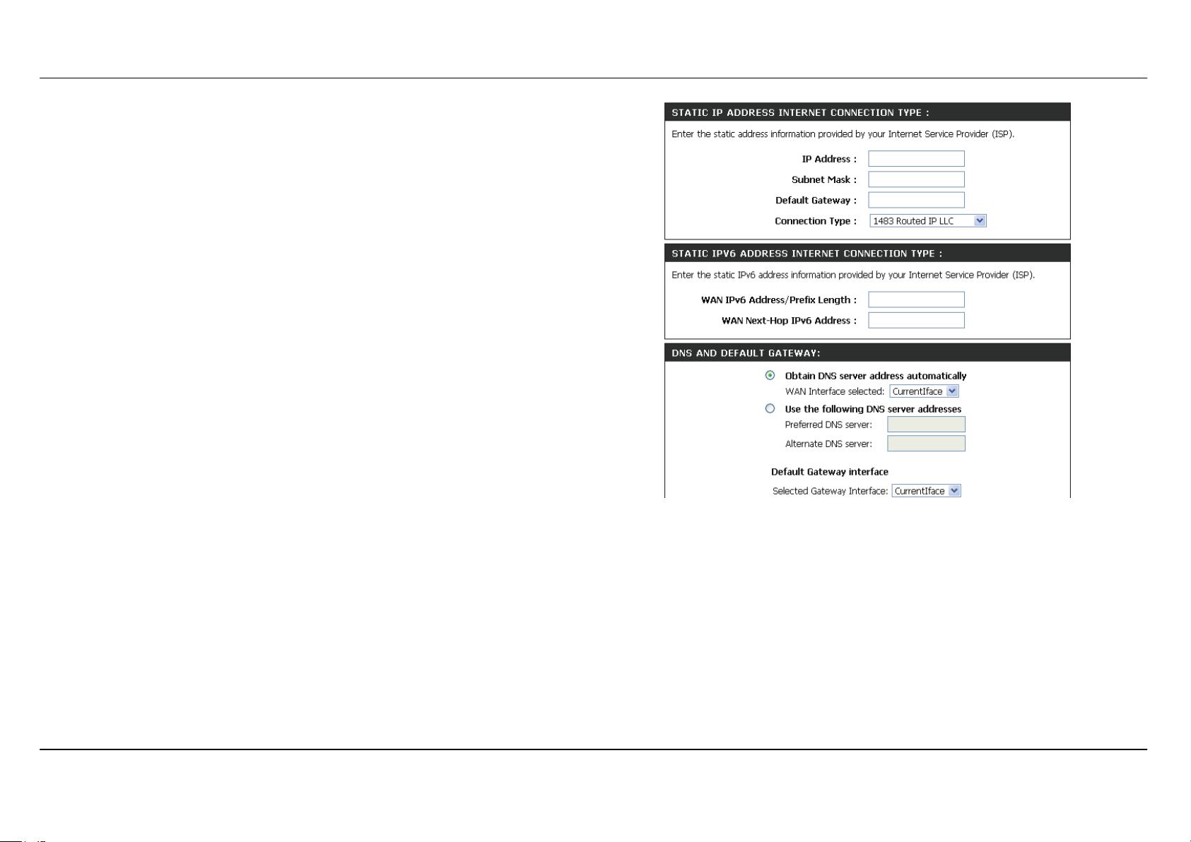
For STATIC IP ADDRESS INTERNET CONNECTION TYPE
Type IP Address, Subnet Mask, Default Gateway, and select
Connection in drop-down menu.
These information should be provided from your Internet Service
Provider (ISP)
STATIC IPv6 ADDRESS INTERNET CONNECTION TYPE
Type WAN IPv6 Address/Prefix Length and WAN Next-Hop IPv6
Address
These information should be provided from your Internet Service
Provider (ISP)
DNS AND DEFAULT GATEWAY
Select Obtain DNS server address automatically to get DNS from
your ISP.
Or Select Use the following DNS server addresses to type the DNS
IP in the Preferred DNS server and Alternate DNS server.
Section 3 - Configuration
D-Link DSL-3580L User Manual
29
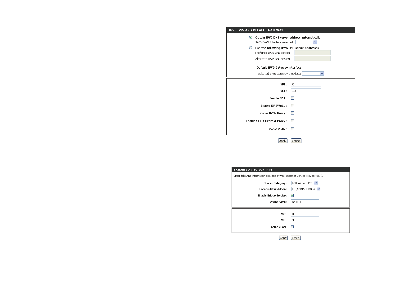
IPv6 DNS AND DEFAULT GATEWAY
Select Obtain IPv6 DNS server address automatically to get DNS
from your ISP.
Or Select Use the following IPv6 DNS server addresses to type the
DNS IPs in the Preferred DNS server and Alternate DNS server.
Select Default IPv6 Gateway Interface in drop-down menu
Set VPI/VCI, enable the Enable NAT.
Enable the Enable Firewall when you want to have the basic filter
function, for example, ICMP ping to DSL-3580L.
Enable the Enable IGMP Multicast Proxy to send IGMP query packets
to the IPTV clients.
Enable VLAN and type the VLAN ID (0-4095) which your ISP assigns.
Click on the Apply button to apply setting.
For BRIDGE CONNECTION TYPE
Select Service Category, Encapsulation Mode in drop-down menu.
Check Enable Bridge Service box and type Service Name.
Set VPI/VCI,
Enable VLAN and type the VLAN ID (0-4095) which your ISP assigns.
Click on the Apply button to apply setting.
Section 3 - Configuration
D-Link DSL-3580L User Manual
30
ETHNET WAN SETUP
To click Setup button from ETHERNET WAN INTERFACE to initiate
Ether WAN configuration.
MANUAL ETH WAN CONNECTION SETUP
This section is same as previous MANUAL ADSL CONNECTION
SETUP section. Here you pick up the connection type, enter access
authorization information, DNS server
Loading...