


 Loading...
Web/Installation Guide
Product Model:


 TM DWS/DXS-3200 Series
Layer 2+ Stackable Gigabit Ethernet Switches with optional XG uplinks
Release 2.0
©Copyright 2006. All rights reserved.

|
Table of Contents |
Table of Contents |
|
DXS/DWS-3227/3227P, DXS/DWS-3250 User Guide Overview .................................................... |
7 |
Intended Audience........................................................................................................................... |
8 |
Device Description .................................................................................................................. |
9 |
Viewing the Device .......................................................................................................................... |
9 |
DXS-3250/DWS Front Panel ..................................................................................................................... |
9 |
DXS/DWS-3227 Front Panel ................................................................................................................... |
10 |
DXS/DWS-3227P Front Panel................................................................................................................. |
10 |
Back Panels............................................................................................................................................. |
11 |
Ports Description ........................................................................................................................... |
12 |
1000Base-T Gigabit Ethernet Ports......................................................................................................... |
12 |
10G XFP Fiber port.................................................................................................................................. |
12 |
Optional Modules..................................................................................................................................... |
12 |
SFP Ports ................................................................................................................................................ |
13 |
RS-232 Console Port............................................................................................................................... |
14 |
Stacking Ports.......................................................................................................................................... |
14 |
Cable Specifications ...................................................................................................................... |
16 |
LED Definitions.............................................................................................................................. |
16 |
Port LEDs ................................................................................................................................................ |
16 |
SFP LEDs ................................................................................................................................................ |
18 |
System LEDs ........................................................................................................................................... |
18 |
Cable, Port, and Pinout Information .............................................................................................. |
20 |
Pin Connections for the 10/100/1000 Ethernet Interface......................................................................... |
20 |
Physical Dimensions ..................................................................................................................... |
22 |
Mounting Device ................................................................................................................... |
25 |
Preparing for Installation................................................................................................................ |
25 |
Installation Precautions............................................................................................................................ |
25 |
Site Requirements ................................................................................................................................... |
26 |
Unpacking................................................................................................................................................ |
26 |
Installing the Device ...................................................................................................................... |
27 |
Desktop or Shelf Installation .................................................................................................................... |
27 |
Rack Installation ...................................................................................................................................... |
27 |
Connecting the Device .................................................................................................................. |
30 |
Connecting the Switch to a Terminal ....................................................................................................... |
30 |
AC Power Connection ............................................................................................................................. |
30 |
Initial Configuration ............................................................................................................... |
31 |
General Configuration Information ................................................................................................ |
31 |
Auto-Negotiation ...................................................................................................................................... |
31 |
Device Port Default Settings.................................................................................................................... |
32 |
Booting the Switch......................................................................................................................... |
32 |
Configuration Overview ................................................................................................................. |
34 |
Page 1

DXS/DSW 3200 Series User Guide
Initial Configuration ................................................................................................................................. |
35 |
Advanced Configuration................................................................................................................ |
38 |
Retrieving an IP Address From a DHCP Server ..................................................................................... |
38 |
Receiving an IP Address From a BOOTP Server ................................................................................... |
39 |
Security Management and Password Configuration............................................................................... |
40 |
Software Download and Reboot ................................................................................................... |
42 |
Software Download through XModem .................................................................................................... |
42 |
Software Download Through TFTP Server............................................................................................. |
42 |
Boot Image Download............................................................................................................................. |
43 |
Configuring Stacking ..................................................................................................................... |
44 |
Startup Menu Functions ................................................................................................................ |
46 |
Download Software................................................................................................................................. |
46 |
Erase FLASH File ................................................................................................................................... |
47 |
Erase FLASH Sectors............................................................................................................................. |
47 |
Password Recovery ................................................................................................................................ |
48 |
WLAN Licence Key ................................................................................................................................. |
48 |
Getting Started...................................................................................................................... |
51 |
Starting the D-Link Embedded Web Interface............................................................................... |
52 |
Understanding the D-Link Embedded Web Interface.................................................................... |
54 |
Device Representation............................................................................................................................ |
55 |
Using the D-Link Embedded Web Interface Management Buttons ........................................................ |
56 |
Using Screen and Table Options .................................................................................................. |
57 |
Adding Configuration Information ........................................................................................................... |
57 |
Modifying Configuration Information ....................................................................................................... |
57 |
Deleting Configuration Information ......................................................................................................... |
58 |
Resetting the Device ..................................................................................................................... |
59 |
Logging Off from the Device ......................................................................................................... |
60 |
Managing Device Information ............................................................................................... |
61 |
Defining the System Description ................................................................................................... |
61 |
Defining Advanced System Settings ............................................................................................. |
63 |
Managing Power over Ethernet Devices............................................................................... |
65 |
Defining PoE System Information ................................................................................................. |
66 |
Displaying and Editing PoE System Information........................................................................... |
68 |
Managing Stacking ............................................................................................................... |
71 |
Understanding the Stack Topology ............................................................................................... |
72 |
Stacking Failover Topology........................................................................................................... |
72 |
Stacking Members and Unit ID ............................................................................................................... |
72 |
Removing and Replacing Stacking Members ......................................................................................... |
73 |
Exchanging Stacking Members..................................................................................................... |
74 |
Switching the Stacking Master ...................................................................................................... |
74 |
Configuring Stacking ..................................................................................................................... |
75 |
Page 2

Table of Contents
Configuring Device Security.................................................................................................. |
77 |
Configuring Management Security ................................................................................................ |
78 |
Configuring Authentication Methods........................................................................................................ |
78 |
Configuring Passwords............................................................................................................................ |
95 |
Configuring Network Security ........................................................................................................ |
99 |
Network Security Overview...................................................................................................................... |
99 |
Defining Network Authentication Properties .......................................................................................... |
101 |
Defining Port Authentication .................................................................................................................. |
103 |
Configuring Traffic Control..................................................................................................................... |
108 |
Defining DOS Protection Security ............................................................................................... |
113 |
Configuring Ports ................................................................................................................ |
115 |
Viewing Port Properties ............................................................................................................... |
118 |
Aggregating Ports ............................................................................................................... |
121 |
Configuring LACP........................................................................................................................ |
122 |
Defining LAG Members ......................................................................................................................... |
124 |
Configuring VLANs ............................................................................................................. |
125 |
Defining VLAN Properties............................................................................................................ |
126 |
Defining VLAN Membership ........................................................................................................ |
128 |
Defining VLAN Interface Settings ................................................................................................ |
130 |
Configuring GARP ....................................................................................................................... |
132 |
Defining GARP ...................................................................................................................................... |
132 |
Defining GVRP ...................................................................................................................................... |
134 |
Configuring Multicast VLANs....................................................................................................... |
136 |
Defining VLAN Groups ................................................................................................................ |
137 |
Defining WLAN ................................................................................................................... |
141 |
Defining WLAN System Properties.............................................................................................. |
142 |
Enabling WLAN ..................................................................................................................................... |
142 |
Defining WLAN Security ........................................................................................................................ |
143 |
Viewing WLAN Rogues ......................................................................................................................... |
147 |
Viewing WLAN Stations......................................................................................................................... |
149 |
Defining WLAN Access Points .................................................................................................... |
150 |
Defining WLAN Access Point Properties ............................................................................................... |
151 |
Adding a New Access point ................................................................................................................... |
152 |
Configuring WLAN VLANs..................................................................................................................... |
153 |
Configuring WLAN Template Settings ................................................................................................... |
154 |
Configuring WLAN Radio Settings .............................................................................................. |
156 |
Defining WLAN Radio Settings.............................................................................................................. |
156 |
Defining BSS Settings ........................................................................................................................... |
158 |
Defining WLAN Power Settings ............................................................................................................. |
162 |
Viewing WLAN Statistics ............................................................................................................. |
164 |
Viewing Access Point Statistics ............................................................................................................. |
164 |
Viewing Radio Interfaces Statistics........................................................................................................ |
166 |
Viewing BSS Statistics........................................................................................................................... |
168 |
Page 3

DXS/DSW 3200 Series User Guide
Viewing WLAN Stations ........................................................................................................................ |
169 |
Configuring IP Information .................................................................................................. |
171 |
Configuring IP Interfaces............................................................................................................. |
171 |
Defining IP Addresses .......................................................................................................................... |
172 |
Defining Default Gateways ................................................................................................................... |
174 |
Configuring DHCP ................................................................................................................................ |
175 |
Configuring ARP ................................................................................................................................... |
177 |
Configuring Domain Name Servers ............................................................................................ |
179 |
Defining DNS Servers........................................................................................................................... |
179 |
Defining DNS Host Mapping ................................................................................................................. |
181 |
Defining the Forwarding Database and Static Routes ........................................................ |
183 |
Defining Static Forwarding Database Entries ............................................................................. |
184 |
Defining Dynamic Forwarding Database Entries ........................................................................ |
186 |
Configuring Routing .................................................................................................................... |
188 |
Configuring Spanning Tree ................................................................................................. |
191 |
Defining Classic Spanning Tree.................................................................................................. |
192 |
Defining STP on Interfaces ......................................................................................................... |
194 |
Defining Rapid Spanning Tree .................................................................................................... |
197 |
Defining Multiple Spanning Tree ................................................................................................. |
198 |
Defining MSTP Instance Settings ......................................................................................................... |
200 |
Defining MSTP Interface Settings......................................................................................................... |
202 |
Configuring Multicast Forwarding ....................................................................................... |
205 |
Defining IGMP Snooping............................................................................................................. |
206 |
Defining Multicast Bridging Groups............................................................................................. |
208 |
Defining Multicast Forward All Settings ................................................................................................ |
210 |
Configuring Multicast TV ............................................................................................................. |
212 |
Defining IGMP Snooping for Multicast TV ............................................................................................ |
212 |
Viewing Multicast TV Members............................................................................................................. |
214 |
Configuring SNMP .............................................................................................................. |
215 |
SNMP v1 and v2c ....................................................................................................................... |
215 |
SNMP v3 ..................................................................................................................................... |
215 |
Configuring SNMP Security ........................................................................................................ |
215 |
Defining SNMP Security ....................................................................................................................... |
216 |
Defining SNMP Views........................................................................................................................... |
217 |
Defining SNMP Group Profiles ............................................................................................................. |
219 |
Defining SNMP Group Members .......................................................................................................... |
222 |
Defining SNMP Communities ............................................................................................................... |
225 |
Configuring SNMP Notifications.................................................................................................. |
227 |
Defining SNMP Notification Global Parameters.................................................................................... |
228 |
Defining SNMP Notification Filters........................................................................................................ |
229 |
Defining SNMP Notification Recipients................................................................................................. |
231 |
Page 4

Table of Contents
Configuring Quality of Service ............................................................................................ |
237 |
Quality of Service Overview ........................................................................................................ |
238 |
VPT Classification Information............................................................................................................... |
238 |
CoS Services ......................................................................................................................................... |
238 |
Defining General QoS Settings ................................................................................................... |
238 |
Configuring QoS General Settings ........................................................................................................ |
238 |
Restoring Factory Default QoS Interface Settings................................................................................. |
241 |
Configure Bandwidth Settings ............................................................................................................... |
241 |
Defining Queues .................................................................................................................................... |
243 |
Configuring QoS Mapping ........................................................................................................... |
244 |
Mapping CoS Values to Queues ........................................................................................................... |
244 |
Mapping DSCP Values to Queues ........................................................................................................ |
245 |
Configuring Advanced QoS Settings ........................................................................................... |
246 |
Defining Policy Properties...................................................................................................................... |
246 |
Defining Tail Dropping ........................................................................................................................... |
248 |
Defining Policy Profiles .......................................................................................................................... |
253 |
Managing System Files....................................................................................................... |
257 |
File Management Overview......................................................................................................... |
257 |
Downloading System Files .......................................................................................................... |
258 |
Firmware Download............................................................................................................................... |
258 |
Configuration Download ........................................................................................................................ |
259 |
Uploading System Files............................................................................................................... |
260 |
Upload Type .......................................................................................................................................... |
260 |
Software Image Upload ......................................................................................................................... |
261 |
Configuration Upload ............................................................................................................................. |
261 |
Activating Image Files ................................................................................................................. |
262 |
Copying Files............................................................................................................................... |
263 |
Restoring the Default Configuration File................................................................................................ |
263 |
Managing System Files ............................................................................................................... |
264 |
Managing System Logs ...................................................................................................... |
265 |
Enabling System Logs................................................................................................................. |
266 |
Viewing the Device Memory Logs ............................................................................................... |
268 |
Clearing Device Memory Logs............................................................................................................... |
268 |
Viewing the FLASH Logs............................................................................................................. |
269 |
Clearing FLASH Logs ............................................................................................................................ |
269 |
Defining Servers Log Parameters ............................................................................................... |
270 |
Managing Device Diagnostics............................................................................................. |
273 |
Configuring Port Mirroring ........................................................................................................... |
274 |
Viewing Integrated Cable Tests................................................................................................... |
277 |
Viewing Optical Transceivers ...................................................................................................... |
279 |
Viewing the CPU Utilization......................................................................................................... |
280 |
Page 5

DXS/DSW 3200 Series User Guide
Configuring System Time.................................................................................................... |
281 |
Configuring Daylight Savings Time ............................................................................................. |
281 |
Configuring SNTP ....................................................................................................................... |
285 |
Polling for Unicast Time Information ..................................................................................................... |
285 |
Polling for Anycast Time Information .................................................................................................... |
285 |
Broadcast Time Information.................................................................................................................. |
285 |
Defining SNTP Global Settings ................................................................................................... |
286 |
Defining SNTP Authentication..................................................................................................... |
288 |
Defining SNTP Servers ............................................................................................................... |
290 |
Defining SNTP Interface Settings ............................................................................................... |
292 |
Viewing Statistics ................................................................................................................ |
295 |
Viewing Interface Statistics ......................................................................................................... |
295 |
Viewing Device Interface Statistics ....................................................................................................... |
296 |
Resetting Interface Statistics Counters................................................................................................. |
297 |
Viewing Port Utilization Statistics.......................................................................................................... |
298 |
Viewing Etherlike Statistics ................................................................................................................... |
299 |
Resetting Etherlike Statistics Counters................................................................................................. |
300 |
Viewing GVRP Statistics....................................................................................................................... |
301 |
Resetting GVRP Statistics Counters..................................................................................................... |
302 |
Viewing EAP Statistics.......................................................................................................................... |
303 |
Managing RMON Statistics ......................................................................................................... |
305 |
Viewing RMON Statistics ...................................................................................................................... |
306 |
Resetting RMON Statistics Counters.................................................................................................... |
307 |
Configuring RMON History ................................................................................................................... |
308 |
Defining RMON Alarms......................................................................................................................... |
315 |
Appendix A, WLAN Country Settings ....................................................................................... |
317 |
Appendix B, Device Specifications & Features ........................................................................ |
325 |
Appendix B, Troubleshooting ................................................................................................... |
333 |
Problem Management................................................................................................................. |
334 |
Troubleshooting Solutions........................................................................................................... |
334 |
Contacting D-Link Technical Support.......................................................................................... |
337 |
Warranty...................................................................................................................................... |
365 |
Product Registration.................................................................................................................... |
369 |
International Offices .................................................................................................................... |
371 |
Page 6

Preface
DXS/DWS-3227/3227P, DXS/DWS-3250 User Guide Overview
Preface
The Embedded Web System (EWS) is a network management system. The D-Link Embedded Web Interface configures, monitors, and troubleshoots network devices from a remote web browser. The D-Link Embedded Web Interface web pages are easy-to-use and easy-to-navigate. In addition, The D-Link Embedded Web Interface provides real time graphs and RMON statistics to help system administrators monitor network performance.
This preface provides an overview to the D-Link Embedded Interface User Guide, and includes the following sections:
•DXS/DWS-3227/3227P, DXS/DWS-3250 User Guide Overview
•Intended Audience
DXS/DWS-3227/3227P, DXS/DWS-3250 User Guide
Overview
This section provides an overview to the D-Link Web System Interface User Guide. The D-Link Web System Interface User Guide provides the following sections:
•Section 1, Device Description — Provides a system description including the hardware components.
•Section 2, Mounting Device — Provides step-by-step instructions for installing the device.
•Section 3, Initial Configuration — Provides step-by-step instructions for the initial device configuration.
•Section 4, Getting Started — Provides information about using the EWS, including The D-Link Embedded Web Interface interface, management, and information buttons, as well as information about adding, modifying, and deleting device information.
•Section 5, Managing Device Information — Provides information about opening the device zoom view, defining general system information, and enabling Jumbo frames.
•Section 6, Managing Power over Ethernet Devices — Provides information about configuring PoE on the device.
•Section 7, Managing Stacking — Provides information about stacking devices.
•Section 8, Configuring Device Security — Provides information about configuring device security for management security, traffic control, and network security.
•Section 9, Configuring Ports — Provides information about configuring ports.
•Section 10, Aggregating Ports — Provides information about configuring Link Aggregated Groups and LACP.
•Section 11, Configuring VLANs — Provides information about configuring and managing VLANs, including information about GARP and GVRP, and defining VLAN groups.
•Section 12, Defining WLAN — Provides information for managing and monitoring WLAN access points.
•Section 13, Configuring IP Information — Provides information about defining device IP addresses, ARP, and Domain Name Servers.
•Section 14, Defining the Forwarding Database and Static Routes — Provides information about configuring and managing both static and dynamic MAC addresses.
•Section 15, Configuring Spanning Tree — Provides information about configuring Spanning Tree Protocol and the Rapid Spanning Tree Protocol.
•Section 16, Configuring Multicast Forwarding — Provides information about Multicast Forwarding.
•Section 17, Configuring SNMP — Provides information about defining SNMP v1,v2c, and v3 management, including SNMP filters and notifications.
Page 7

DXS/DWS 3200 Series User Guide
•Section 18, Configuring Quality of Service — Provides information about configuring Quality of Service on the device.
•Section 19, Managing System Files — Provides information about downloading, uploading, and copying system files.
•Section 20, Managing System Logs — Provides information about enabling and defining system logs.
•Section 21, Managing Device Diagnostics — Provides information about configuring port mirroring, testing copper and fiber cables, and viewing device health information.
•Section 22, Configuring System Time — Provides information about configuring system time, including Daylight Savings Time parameters and Simple Network Time Protocol (SNTP) parameters.
•Section 23, Viewing Statistics — Provides information about viewing device statistics, including RMON statistics, device history events, and port and LAG utilization statistics.
•Appendix A, WLAN Country Settings — Provides information for configuring WLAN, including the country codes, power regulations, and frequency ranges.
•Appendix B, Troubleshooting — Provides basic troubleshooting for installing the device.
Intended Audience
This guide is intended for network administrators familiar with IT concepts and terminology.
Page 8
Device Description
Viewing the Device
Section 1. Device Description
This section contains a description of the D-Link DWS/DXS-3250 and D-Link DWS/DXS-3227/3227P, and contains the following topics:
•Viewing the Device
•Ports Description
•Cable Specifications
•LED Definitions
•Cable, Port, and Pinout Information
•Physical Dimensions
Viewing the Device
The devices described in this section are stackable Gigabit Ethernet Managed Switches. Device management is performed using an Embedded Web Server (EWS) or through a Command Line Interface (CLI). The device configuration is performed via an RS-232 interface.
This section contains descriptions for the following:
•DXS-3250/DWS Front Panel
•DXS/DWS-3227 Front Panel
•DXS3227P Front Panel
•Back Panels
DXS-3250/DWS Front Panel
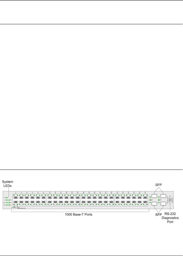
The D-Link DXS/DWS-3250 is a 48 port Gigabit Ethernet Managed Switch. The device contains 48 gigabit network ports and 4 SFP Ports on the front panel for network connectivity, and 2 stacking ports on the back panel. The following figure illustrates the DXS-3250 front panel.
Figure 1: DXS/DWS-3250 Front Panel
Page 9
DXS/DWS 3200 Series User Guide
The device front panel is configured as follows:
•48 Gigabit Ethernet ports — RJ-45 ports designated as 10/100/1000Base-T . The RJ-45 ports are designated as ports Ports 1-48.
•RS-232 Console port — An asynchronous serial console port supporting the RS-232 electrical specification. The port is used to connect the device to the console managing the device.
•4 SFP Ports — There are four SFP port, which contains 1000Base-X (fiber) connections.
On the front panel there are the Port activity LEDs on each port with the system LEDs displayed separately.
DXS/DWS-3227 Front Panel
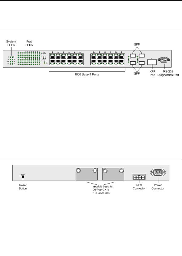
The D-Link DXS-3227 is a 24 port Gigabit Ethernet Managed Switch. The device contains 24 gigabit network ports, 4 SFP ports and 1XFP 10G port on the front panel for network connectivity, and 2 optional stacking or uplink module bays on the back panel.
The following figure illustrates the DXS-3227 front panel:
Figure 2: DXS/DWS-3227 Front Panel
The device front panel is configured as follows:
•24 Gigabit Ethernet ports — RJ-45 ports designated as 10/100/1000Base-T . The RJ-45 ports are designated as ports Ports 1-24.
•RS-232 Console port — An asynchronous serial console port supporting the RS-232 electrical specification. The port is used to connect the device to the console managing the device.
•4 SFP Ports — There are four SFP port, which contains 1000Base-X (fiber) connections.
•XFP port — Hot-swappable optical interface for 10 Gigabit, Fibre Channel, Gigabit Ethernet, and other applications.
On the front panel there are the Port activity LEDs on each port with the system LEDs displayed separately.
DXS/DWS-3227P Front Panel
The D-Link DXS-3227P is a 24 port Gigabit Ethernet Managed Switch. The device contains 24 gigabit network ports, 4 SFP ports and 1XFP 10G port on the front panel for network connectivity, and 2 optional stacking or uplink module bays on the back panel. The DXS-3227P model also supports Power Over Ethenret.
Page 10
Device Description
Viewing the Device
The following figure illustrates the DXS-3227 front panel:
Figure 3: DXS/DWS-3227P Front Panel
The device front panel is configured as follows:
•24 Gigabit Ethernet ports — RJ-45 ports designated as 10/100/1000Base-T . The RJ-45 ports are designated as ports Ports 1-24.
•RS-232 Console port — An asynchronous serial console port supporting the RS-232 electrical specification. The port is used to connect the device to the console managing the device.
•4 SFP Ports — There are four SFP port, which contains 1000Base-X (fiber) connections.
•XFP port — Hot-swappable optical interface for 10 Gigabit and other applications.
On the front panel there are the Port activity LEDs on each port with the system LEDs displayed separately.
Back Panels
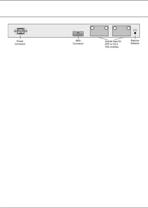
The following figures illustrate DXS-3250, DXS-3227 and DXS-3227P back panels:
Figure 4: DXS/DWS-3250 and DXS/DWS-3227 Back Panel
Page 11
DXS/DWS 3200 Series User Guide
Figure 5: DXS/DWS-3227P Back Panel
The DXS-3200 series back panel is configured as follows:
•Reset Button — Resets the device. The Reset button does not extend beyond the device’s front panel surface. This it to avoid accidental device resetting.
•2 Stacking Connectors — The devices provide two stacking 12 Link(XG) interface ports.
•RPS Connector — Redundant Power Supply (RPS) DC connector.
•Power Connector — AC power supply interface.
Ports Description
This section describes the device ports and includes the following topics:
•1000Base-T Gigabit Ethernet Ports
•10G XFP Fiber port
•CX-4 Copper Port
•SFP Ports
•Cable Specifications
1000Base-T Gigabit Ethernet Ports
The device contains a 1000 Base-TX Gigabit 24/48 port. The port is an RJ-45 port which supports halfand fullduplex mode 10/100/1000 Mbps.
10G XFP Fiber port
10Gigabit XFP fiber port. One fixed in DXS/DWS-3227/3227P models.
Optional Modules
The 3200 series have module bays located on the back panel into which optional modules (DEM-411X and DEM411XT) can be inserted and then provide additional 10Gigabit copper or fiber port.
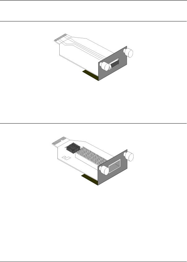
CX-4 Copper Port
An optional 10Gigabit copper port. DEM-411T expansion module is inserted in one or two bays located on the back panel.
The following figure describes the DEM - 411T module used for a copper port:
Page 12
Device Description
Ports Description
Figure 6: CX-4 Expansion Module
10G XFP Fiber port
An optional 10Gigabit fiber port that can be inserted to the modules bays located on the back panel.
The following figure describes the DEM - 411X module used for a fiber port: Transceivers can be purchased separately from D-Link.
Figure 7: XFP Expansion Module
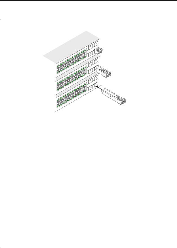
SFP Ports
Small Form Factor Pluggable (SFP) Optical Transceivers are integrated duplex data mini-GBIC links for bi-direc- tional communication over multimode optical fiber, designed for high-speed Fiber Channel data links. The SFP port is designated as 1000Base-X.
The SFP (mini-GBIC) port can be removed and inserted as required. The following figure illustrates the mini-GBIC insertion.
The following figure illustrates how to insert an SFP into the device:
Page 13
DXS/DWS 3200 Series User Guide
Figure 8: Inserting an SFP into the Device
RS-232 Console Port
The RS-232 port is an asynchronous serial console port supporting the RS-232 electrical specification. The port is used to connect the device to a console managing the device. This interface configuration is as follows:
•Eight data bits.
•One stop bit.
•No parity.
•Baud rate is 9600 (default). The user can change the rate from 115200 down to 9600 bps.
•Console speeds of 57600 and 115200.
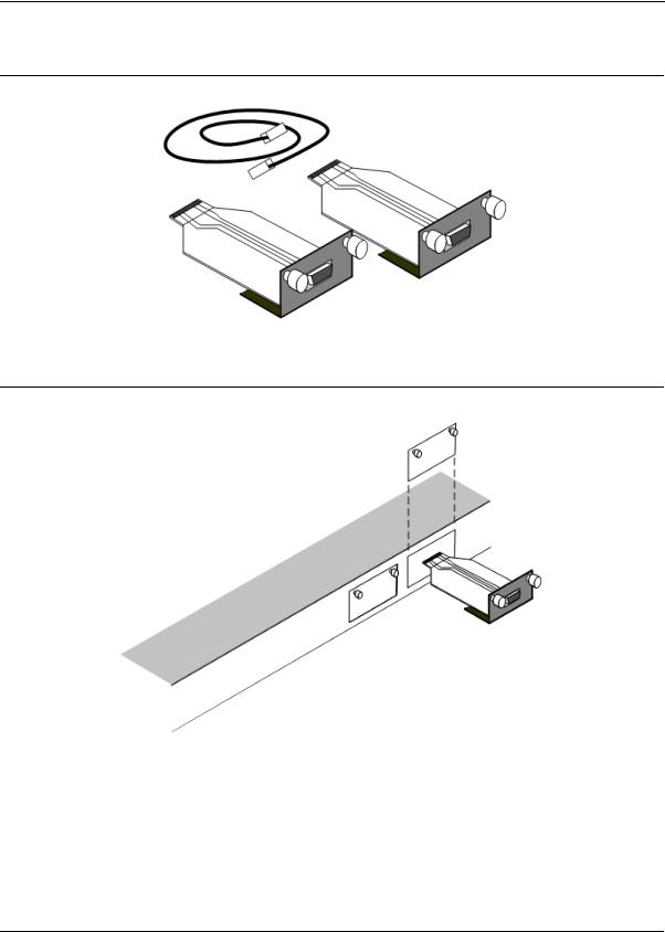
Stacking Ports
The device has two optional stacking interface ports. One stacking port provides an Up connection, while the second provides a Down stacking connection. A 4X to 4X Infinidband Cable is used to connect devices in the stacking configuration.
The DEM - 411S Stacking kit includes:
a)0.5m CX-4 cable
b)Two DEM - 411T modules
The following figure descrives the DEM - 411S Stacking kit’s components:
Page 14
Device Description
Ports Description
Figure 9: Stacking Kit (Optional)
Figure 10: Inserting a Module Into a Device
To insert a module into a device:
1.Release bay cover bolts.
2.Remove bay cover.
3.Carefully Insert module into its proper slot.
4.Ensure that the module is inserted correctly.
5.Secure module bolts.
Page 15

DXS/DWS 3200 Series User Guide
Cable Specifications
The following table contains the various cable specification for the DXS/DWS-3200 series:
Table 1: |
DXS-3250/DXS-3227P Cables and Optical Modules Specifications |
||
Cable Type |
Description |
||
|
|
||
1000Base-T |
UTP Cat. 5e (100 meters max.) |
||
|
|
UTP Cat. 5 (100 meters max.) |
|
|
|
EIA/TIA-568B 150-ohm STP (100 meters max.) |
|
|
|
|
|
10G CX-4 |
|
10Gigabit copper port (Up to 15m) |
|
|
|
||
1000BASE-LX |
Single-mode fiber module (10Km) |
||
|
|
||
1000BASE-SX |
Multi-mode fiber module (550m) |
||
|
|
||
1000BASE-LH |
Single-mode fiber module (40km) |
||
|
|
||
1000BASE-ZX |
Single-mode fiber module (80km) |
||
|
|
||
10Gigabit - XFP |
|
||
Please refer to the D-Link |
Single/Multiple fiber XFP transceiver |
||
datasheet for DEM-421XT and |
|||
|
|||
DEM-422XT should there be |
|
||
any questions |
|
||
|
|
|
|
LED Definitions
The device front panels contain Light Emitting Diodes (LED) that indicate the device status.The different LED types are as follows:
•Port LEDs — Indicate each port status.
•SFP Ports — Indicate SFP port status.
•System — Indicating the device power supply status.
Port LEDs
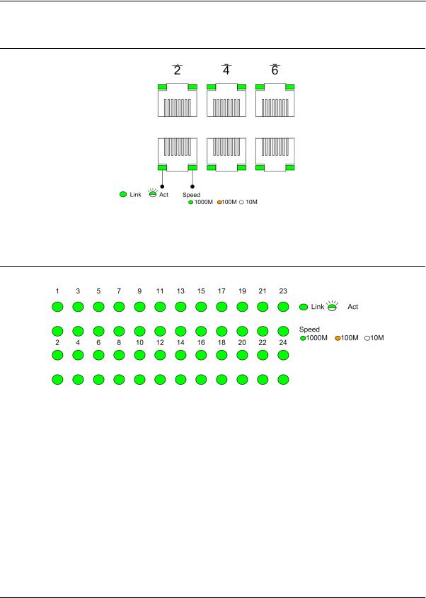
1000Base-T Gigabit Ethernet RJ-45 Port LEDs
The LEDs on the three devices are differently indicated. The following figure illustrates the DXS-3250 port LEDs.
Page 16
Device Description
LED Definitions
Figure 10: DXS-3250 1000Base-T Gigabit Ethernet RJ-45 Port LEDs
The DXS-3227 device has the LED indications on a LED panel on the left side of the device. The following figure illustrates the port LEDs:
Figure 11: DXS-3227 1000Base-T Gigabit Ethernet RJ-45 Port LEDs
The RJ-45 ports on both devices have two LEDs, one for speed, and one for Link /activity. The LED indications are described in the following table:
Table 2: |
1000Base-T Gigabit Ethernet RJ-45 Port LED Indications |
||
Port Description |
LED Indication |
Description |
|
|
|
|
|
Speed |
|
Green |
A 1000-Mbps link is established on the port. |
|
|
|
|
|
|
Amber |
A 100-Mbps link is established on the port. |
|
|
|
|
|
|
Off |
A 10-Mbps link is established on the port. |
|
|
|
|
Link/Activity LED |
Green |
A link is established on the port. |
|
|
|
|
|
|
|
Flashing Green |
There is data transmission on the port. |
|
|
|
|
|
|
Off |
No link is established on the port. |
|
|
|
|
Page 17
DXS/DWS 3200 Series User Guide
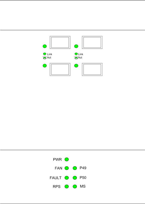
SFP LEDs
The following figure illustrates the port LEDs.
Figure 12: SFP LEDs
The Fiber ports each have one LED. The LED indications are described in the following table:
Table 3: SFP LED Indications
LED Indication |
Description |
|
|
Green |
A link is established on the port. |
|
|
Flashing Green |
There is data transmission on the port. |
|
|
Off |
No link is established on the port. |
|
|
System LEDs
The three devices have different system LEDs.
DXS-3250
The sytstem LEDs on the DXS-3250 device in on the left side of the device. The following figure illustrates the DXS-3250 system LEDs:
Figure 13: DXS-3250 System LEDs
Page 18
Device Description
LED Definitions
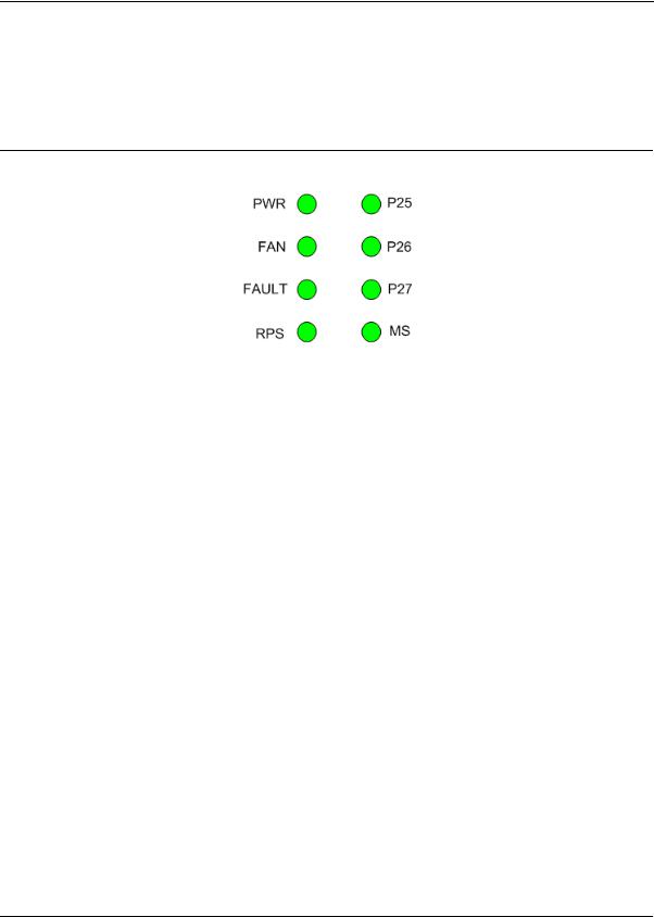
DXS/DWS-3227/3227P
The sytstem LEDs are on the DXS/DWS-3227/3227P device in on the left side of the device. The following figure illustrates the DXS/DWS-3227/3227P system LEDs:
Figure 14: DXS/DWS-3227/3227P LEDs
The LED indications are described in the following table:
Table 4: |
System’s LED Indications |
|
|
|
LED Description |
LED |
Description |
||
|
|
Indication |
|
|
|
|
|
|
|
PWR |
|
Green |
The device is powered up. |
|
|
|
|
|
|
|
|
Off |
The device is not powered up. |
|
|
|
|
|
|
FAN |
|
Red |
Indicates a faulty fan. |
|
|
|
|
|
|
|
|
Off |
All fans are functioning correctly. |
|
|
|
|
|
|
Fault |
|
Red Flashing |
The device is currently running POST. |
|
|
|
|
|
|
|
|
Red |
The device detected POST running error. |
|
|
|
|
|
|
RPS |
|
Green |
The device is powered through the RPS. |
|
|
|
|
|
|
|
|
Off |
The device is powered through the AC. |
|
|
|
|
||
P49/P50 (DXS/DWS-3250) - Link/Act for |
Green |
Link established on the port. |
||
XG port |
|
|||
|
|
|
||
|
|
|
||
P25/P26/P27 (DXS/DWS-3227/3227P) - |
Green |
Link established on the port. |
||
Link/Act for XG port |
||||
|
|
|||
|
|
|
|
|
|
|
Green Flashing |
There is data transmission on the port. |
|
|
|
|
|
|
|
|
Off |
No link is established on the port. |
|
|
|
|
|
|
MS |
|
Red |
Device is designated as the stack Master. |
|
|
|
|
|
|
|
|
Green |
Device is designated as stack member. |
|
|
|
|
|
|
|
|
Off |
Not a member of a stack (standalone). |
|
|
|
|
|
|
PoE |
|
Green |
Power is provided at this port |
|
|
|
|
|
|
|
|
Off |
Power is not provided at this port |
|
|
|
|
|
|
Page 19
DXS/DWS 3200 Series User Guide
Table 4: |
System’s LED Indications |
|
|
LED Description |
LED |
Description |
|
|
|
Indication |
|
|
|
|
|
|
|
Amber |
An error is occurred at this port |
|
|
|
|
|
|
Off |
There is no error at this port |
|
|
|
|
|
|
alternating Green |
An error is occurred at this port |
|
|
and Amber |
|
|
|
|
|
|
|
|
|
Cable, Port, and Pinout Information
This section describes the devices physical interfaces and provides information about cable connections. Stations are connected to the device ports through the physical interface ports on the front panel. For each station, the appropriate mode (Half/Full Duplex, Auto Negotiation) is set. The default is Auto Negotiation.
Pin Connections for the 10/100/1000 Ethernet Interface
The switching port can connect to stations wired in standard RJ-45 Ethernet station mode using straight cables. Transmission devices connected to each other use crossed cables. The following figure illustrates the pin allocation.
Figure 15: RJ-45 Pin Allocation
The following table describes the pin allocation:
Table 5: RJ-45 Pin Connections for 10/100/1000 Base-TX
Pin Use
1TxRx 1+
2TxRx 1-
3TxRx 2+
4TxRx 2-
5TxRx 3+
6TxRx 3-
7TxRx 4+
8TxRx 4-
Page 20

Device Description
Cable, Port, and Pinout Information
Figure 16: CX-4 Pin Allocation
The following table describes the pin allocation
Table 6: |
CX-4 Port Pin Connections |
Pin |
Use |
|
|
S1 |
Rx 0+ |
2Rx 0-
3Rx 1+
4Rx 1-
5Rx 2+
6Rx 2-
7Rx 3+
8Rx 3-
9Tx 3-
10Tx 3+
11Tx 2-
12Tx 2+
13Tx 1-
14Tx 1+
15Tx 0-
16Tx 0+-
Page 21
DXS/DWS 3200 Series User Guide
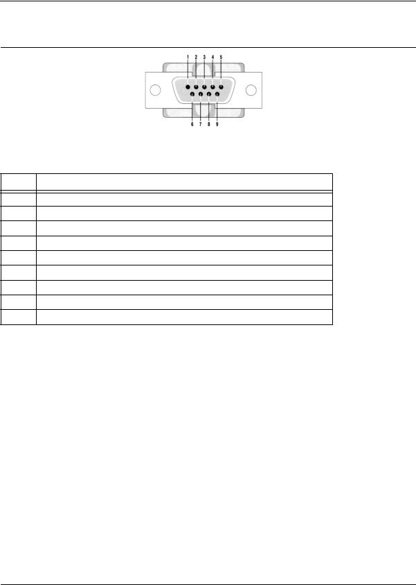
Figure 17: DB-9 Pin Allocation
The following table describes the pin allocation
Table 7: DB-9 Port Pin Connections
Pin Use
1N/A
2RXD
3TXD
4N/A
5GND
6N/A
7N/A
8N/A
9N/A
Physical Dimensions
The device has the following physical dimensions:
DXS/DWS - 3250 / DXS/DWS - 3227P
•Width: 440 mm (17.32 inch)
•Depth: 430mm (16.93 inch)
•Height: 44 mm (1.77 inch)
DXS/DWS - 3227
•Width: 440 mm (17.32 inch)
•Depth: 310 mm (12.20 inch)
•Height: 44 mm (1.77 inch)
Page 22

Device Description
Physical Dimensions
This page is left blank intentionally.
Page 23

DXS/DWS 3200 Series User Guide
Page 24

Mounting Device
Preparing for Installation
Section 2. Mounting Device
This section contains information for installing the device, and includes the following sections:
•Preparing for Installation
•Installing the Device
•Connecting the Device
•Rack Installation
Preparing for Installation
This section provides an explanation for preparing the installation site, and includes the following topics:
•Installation Precautions
•Site Requirements
•Unpacking
Installation Precautions
Warnings
•The surface on which the switch is placed should be adequately secured to prevent it from becoming unstable and/or falling over.
•Ensure the power source circuits are properly grounded.
•Observe and follow service markings. Do not service any product except as explained in your system documentation. Opening or removing covers marked with a triangular symbol with a lighting bolt may cause electrical shock. These components are to be serviced by trained service technicians only.
•Ensure the power cable, extension cable, and/or plug is not damaged.
•Ensure the product is not exposed to water.
•Ensure the device is not exposed to radiators and/or heat sources.
•Do not push foreign objects into the device, as it may cause a fire or electric shock.
•Use the device only with approved equipment.
•Allow the product to cool before removing covers or touching internal equipment.
•Ensure the switch does not overload the power circuits, wiring, and over-current protection. To determine the possibility of overloading the supply circuits, add together the ampere ratings of all devices installed on the same circuit as the device being installed. Compare this total with the rating limit for the circuit. The maximum ampere ratings are usually printed on the switch, near their AC power connectors.
Cautions
•Ensure the air flow around the front, sides, and back of the switch is not restricted.
•Ensure the cooling vents are not blocked.
•Do not install the switch in an environment where the operating ambient temperature might exceed 40ºC (104ºF).
Page 25

DXS/DWS 3200 Series User Guide
Site Requirements
The device is placed on a table-top. Before installing the unit, verify that the location chosen for installation meets the following site requirements.
•General — Ensure that the power supply is correctly installed.
•Power — The unit is installed within 1.5 m (5 feet) of a grounded, easily accessible outlet 100-250 VAC, 5060 Hz.
•Clearance — There is adequate frontal clearance for operator access. Allow clearance for cabling, power connections and ventilation.
•Cabling — The cabling is routed to avoid sources of electrical noise such as radio transmitters, broadcast amplifiers, power lines and fluorescent lighting fixtures.
•Ambient Requirements — The ambient unit operating temperature range is 0 to 40ºC (32 to 104ºF) at a relative humidity of up to 95%, non-condensing. Verify that water or moisture cannot enter the device casing.
Unpacking
This section contains information for unpacking the device, and includes the following topics:
•Package Contents
•Unpacking Essentials
Package Contents
While unpacking the device, ensure that the following items are included:
•The device
•Four rubber feet with adhesive backing
•Rack kit
•An AC power cable
•Console RS-232 cable with DB-9 connector
•Documentation CD
Unpacking Essentials
Note
Before unpacking the device, inspect the package and report any evidence of damage immediately.
To unpack the device perform the following:
1.It is recommended to put on an ESD wrist strap and attach the ESD clip to a metal surface to act as ground. An ESD strap is not supplied with the device.
2.Place the container on a clean flat surface and cut all straps securing the container.
3.Open the container.
4.Carefully remove the device from the container and place it on a secure and clean surface.
5.Remove all packing material.
6.Inspect the product for damage. Report any damage immediately.
If any item is found missing or damaged, please contact your local D-Link reseller for replacement.
Page 26
Mounting Device
Installing the Device
Installing the Device
The device can be installed on a flat surface or mounted in a rack. This section includes the following topics:
•Desktop or Shelf Installation
•Rack Installation
Desktop or Shelf Installation
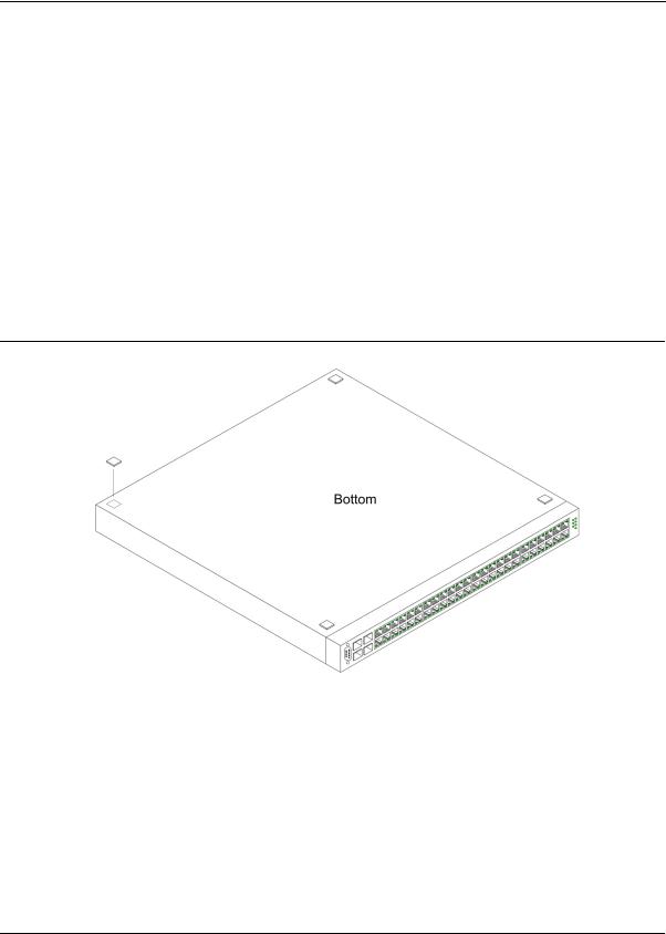
When installing the switch on a desktop or shelf, the rubber feet included with the device should first be attached. Attach these cushioning feet on the bottom at each corner of the device.
Ensure the surface is be able to support the weight of the device and the device cables. To install the device on a surface, perform the following:
1.Attach the rubber feet on the bottom of the device. The following figure illustrates the rubber feet installation on the device.
Figure 18: Installing Rubber Feet
2.Set device down on a flat surface, while leaving 2 inches on each side and 5 inches at the back.
3.Ensure that the device has proper ventilation by allowing adequate space for ventilation between the device and the objects around the device.
Rack Installation
The device can be mounted in an EIA standard-sized, 19-inch rack, which can be placed in a wiring closet with other equipment. To install, the device the mounting brackets must first be attached on the devices’s sides.
Page 27
DXS/DWS 3200 Series User Guide
Notes
•Disconnect all cables from the unit before mounting the device in a rack or cabinet.
•When mounting multiple devices into a rack, mount the devices from the bottom up. To install the device in a rack, perform the following:
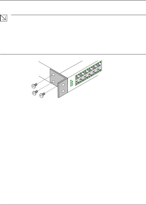
1.Place the supplied rack-mounting bracket on one side of the device ensuring the mounting holes on the device line up to the mounting holes on the rack mounting bracket. The following figure illustrates where to mount the brackets.
Figure 19: Attaching the Mounting Brackets
2.Insert the supplied screws into the rack mounting holes and tighten with a screwdriver.
3.Repeat the process for the rack-mounting bracket on the other side of the device.
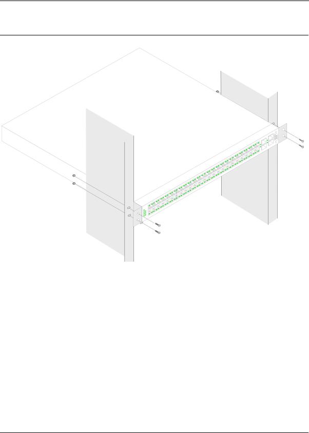
4.Insert the unit into the 19-inch rack ensuring the rack-mounting holes on the device line up to the mounting hole on the rack. The following figure illustrates lining up and mounting the device in the rack.
Page 28
Mounting Device
Installing the Device
Figure 20: Mounting Device in a Rack
5.Secure the unit to the rack with the rack screws (not provided). Fasten the lower pair of screws before the upper pair of screws. This ensures that the weight of the unit is evenly distributed during installation. Ensure that the ventilation holes are not obstructed.
Page 29
Loading...