


D-Link DSL-2790U User Manual |
1 |

Table of Contents
D-Link DSL-2790U User Manual |
2 |
PACKAGE CONTENTS ...................................................................................................... |
4 |
SYSTEM REQUIREMENTS................................................................................................. |
4 |
FEATURES ....................................................................................................................... |
5 |
HARDWARE OVERVIEW............................................................................................. |
7 |
Connections ............................................................................................................... |
7 |
INSTALLATION .............................................................................................................. |
9 |
BEFORE YOU BEGIN........................................................................................................ |
9 |
INSTALLATION NOTES..................................................................................................... |
9 |
INFORMATION YOU WILL NEED FROM YOUR ADSL SERVICE PROVIDER.................. |
11 |
INFORMATION YOU WILL NEED ABOUT DSL-2790U.................................................. |
12 |
DEVICE INSTALLATION ................................................................................................. |
14 |
Power on Router...................................................................................................... |
14 |
Factory Reset Button ............................................................................................... |
15 |
Network Connections............................................................................................... |
15 |
CONFIGURATION........................................................................................................ |
16 |
WEB-BASED CONFIGURATION UTILITY......................................................................... |
16 |
DEVICE INFO ................................................................................................................ |
17 |
SUMMARY ..................................................................................................................... |
18 |
WAN ............................................................................................................................ |
19 |
STATISTICS.................................................................................................................... |
19 |
ROUTE........................................................................................................................... |
22 |
ARP .............................................................................................................................. |
22 |
DHCP ........................................................................................................................... |
22 |
ADVANCED SETUP...................................................................................................... |
23 |
LAYER2 INTERFACE ...................................................................................................... |
23 |
ATM Interface.......................................................................................................... |
24 |
ETH Interface .......................................................................................................... |
25 |
WAN SERVICE.............................................................................................................. |
26 |
LAN.............................................................................................................................. |
49 |
NAT.............................................................................................................................. |
50 |
Virtual Servers......................................................................................................... |
50 |
Port Triggering........................................................................................................ |
51 |
DMZ Host ................................................................................................................ |
52 |
IP Address Map ....................................................................................................... |
53 |
ALG.............................................................................................................................. |
54 |
SECURITY...................................................................................................................... |
55 |
IP Filtering .............................................................................................................. |
55 |
MAC Filtering ......................................................................................................... |
58 |
Dos........................................................................................................................... |
59 |
PARENTAL CONTROL .................................................................................................... |
59 |
URL Filter ............................................................................................................... |
60 |
3G ............................................................................................................................ |
61 |
3G Failover ............................................................................................................. |
62 |
QUALITY OF SERVICE.................................................................................................... |
63 |
Queue Config........................................................................................................... |
64 |
QoS Classification ................................................................................................... |
65 |
ROUTING ....................................................................................................................... |
66 |
Default Gateway ...................................................................................................... |
66 |
Static Route.............................................................................................................. |
66 |
Policy Routing ......................................................................................................... |
67 |
RIP........................................................................................................................... |
68 |
DNS.............................................................................................................................. |
69 |
DNS Server .............................................................................................................. |
69 |
Dynamic DNS .......................................................................................................... |
70 |
DSL .............................................................................................................................. |
71 |
UPNP............................................................................................................................ |
73 |
DNS PROXY.................................................................................................................. |
73 |
PRINT SERVER............................................................................................................... |
74 |
STORAGE SERVICE ........................................................................................................ |
74 |
INTERFACE GROUPING .................................................................................................. |
75 |
IP TUNNEL .................................................................................................................... |
77 |
IPv6inIPv4 ............................................................................................................... |
77 |
IPv4inIPv6 ............................................................................................................... |
78 |
IPSEC ............................................................................................................................ |
79 |
CERTIFICATE ................................................................................................................. |
80 |
LOCAL........................................................................................................................... |
80 |
TRUSTED CA................................................................................................................. |
82 |
POWER MANAGEMENT.................................................................................................. |
83 |
MULTICAST ................................................................................................................... |
84 |
WIRELESS...................................................................................................................... |
85 |
BASIC ............................................................................................................................ |
85 |
SECURITY...................................................................................................................... |
86 |
MAC FILTER................................................................................................................. |
87 |
WIRELESS BRIDGE ........................................................................................................ |
88 |
ADVANCED ................................................................................................................... |
88 |
STATION INFO ............................................................................................................... |
89 |
DIAGNOSTICS............................................................................................................... |
89 |
MANAGEMENT............................................................................................................. |
90 |
SETTINGS ...................................................................................................................... |
90 |
SYSTEM LOG ................................................................................................................. |
91 |
SECURITY LOG .............................................................................................................. |
92 |
TR-069 CLIENT............................................................................................................. |
93 |
INTERNET TIME ............................................................................................................. |
94 |
ACCESS CONTROL......................................................................................................... |
95 |
Passwords................................................................................................................ |
95 |
Services.................................................................................................................... |
96 |
IP Address ............................................................................................................... |
96 |
UPDATE SOFTWARE ...................................................................................................... |
97 |
REBOOT......................................................................................................................... |
98 |
TOOLS ........................................................................................................................... |
98 |
TROUBLESHOOTING ............................................................................................... |
100 |
NETWORKING BASICS ............................................................................................ |
102 |
CHECK YOUR IP ADDRESS.......................................................................................... |
102 |
STATICALLY ASSIGN AN IP ADDRESS ......................................................................... |
103 |
USAGE OF USB INTERFACE ................................................................................... |
104 |
DRIVER AUTOMATIC INSTALLATION........................................................................... |
104 |
DRIVER AUTOMATIC UNINSTALLATION...................................................................... |
107 |
DRIVER MANUAL INSTALLATION................................................................................ |
108 |
DRIVER MANUAL UNINSTALLATION........................................................................... |
112 |
TECHNICAL SPECIFICATIONS.............................................................................. |
114 |
Section 1 - Product Overview
Package Contents
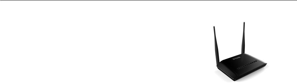
DSL-2790U Wireless ADSL Router
Power Adapter
CD-ROM with User Manual
One Micro Splitter
One twisted-pair telephone cable used for ADSL connection
One straight-through Ethernet cable
One Quick Installation Guide
Note: Using a power supply with a different voltage rating than the one included with the DSL-2790U will cause damage and void the warranty for this product.
System Requirements
ADSL Internet service
Computer with:
200MHz Processor
64MB Memory
CD-ROM Drive
Ethernet Adapter with TCP/IP Protocol Installed
Internet Explorer v6 or later, FireFox v1.5
Computer with Windows 2000, Windows XP, or Windows Vista

Section 1 - Product Overview
11
Features
PPP (Point-to-Point Protocol) Security – The DSL-2790U ADSL Router supports PAP (Password Authentication Protocol) and CHAP (Challenge Handshake Authentication Protocol) for PPP connections. The Router also supports MSCHAP.
DHCP Support – Dynamic Host Configuration Protocol automatically and dynamically assigns all LAN IP settings to each host on your network. This eliminates the need to reconfigure every host whenever changes in network topology occur.
Network Address Translation (NAT) – For small office environments, the DSL-2790U allows multiple users on the LAN to access the Internet concurrently through a single Internet account. This provides Internet access to everyone in the office for the price of a single user. NAT improves network security in effect by hiding the private network behind one global and visible IP address. NAT address mapping can also be used to link two IP domains via a LAN-to-LAN connection.
TCP/IP (Transfer Control Protocol/Internet Protocol) – The DSL-2790U supports TCP/IP protocol, the language used for the Internet. It is compatible with access servers manufactured by major vendors.
RIP-1/RIP-2 – The DSL-2790U supports both RIP-1 and RIP-2 exchanges with other routers. Using both versions lets the Router to communicate with all RIP enabled devices.
Static Routing – This allows you to select a data path to a particular network destination that will remain in the routing table and never “age out”. If you wish to define a specific route that will always be used for data traffic from your LAN to a specific destination within your LAN (for example to another router or a server) or outside your network (to an ISP defined default gateway for instance).
Default Routing – This allows you to choose a default path for incoming data packets for which the destination address is unknown. This is particularly useful when/if the Router functions as the sole connection to the Internet.
ATM (Asynchronous Transfer Mode) – The DSL-2790U supports Bridged Ethernet over ATM (RFC1483), IP over ATM (RFC1577), and PPP over ATM (RFC 2364).
Precise ATM Traffic Shaping – Traffic shaping is a method of controlling the flow rate of ATM data cells. This function helps to establish the Quality of Service for ATM data transfer.
G.hs (Auto-handshake) – This allows the Router to automatically choose either the G.lite or G.dmt ADSL connection standards.
High Performance – Very high rates of data transfer are possible with the Router. Up to 8 Mbps downstream bit rate using the G.dmt standard.

Section 1 - Product Overview
Full Network Management – The DSL-2790U incorporates SNMP (Simple Network Management Protocol) support for web-based management and text-based network management via an RS-232 or Telnet connection.
Telnet Connection – The Telnet enables a network manager to access the Router’s management software remotely.
Easy Installation – The DSL-2790U uses a web-based graphical user interface program for convenient management access and easy set up. Any common web browser software can be used to manage the Router.
Section 1 - Product Overview
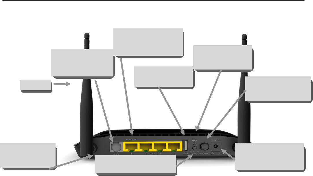
Hardware Overview
Connections
ADSL Port
Use the ADSL cable to connect to the your telephone line (RJ-11 port)
Antenna
Ethernet Port
Use the Ethernet port to connect the Router to a computer or an Ethernet LAN
USB Port
Use the USB port to connect to the computer
WPS Button
Push the button to on/off
WPS function
Power Button
Push in to power-on the Router. Push again to poweroff the Router.
Reset Button
On the bottom of the device push it to reset to factory confugration
Wireless ON/OFF Button
Push the button to on/off wireless function
Power Insert
Use the adapter shipped with the Router to connect to power source.
Section 1 - Product Overview
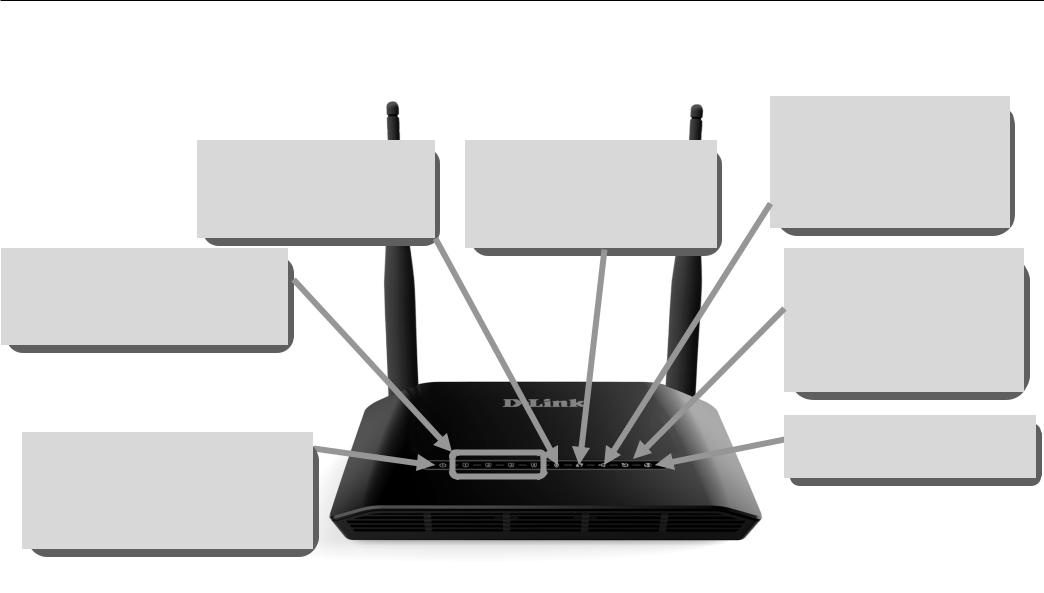
Hardware Overview LEDs
WLAN
A steady green light indicates a wireless connection. A blinking green light indicates activity on the WLAN interface.
LAN
A solid green light indicates a valid link on startup. This light will blink when there is activity currently passing through the Ethernet port.
Power
A steady green light indicates the unit is powered on. When the device is powered off it remains dark. Lights steady green during power on self-test (POST) means the power connection works properly.
WPS
A blinking green light indicates the device has connected the wireless network card, A blinking green light indicates activity on WPS.
USB
A steady green light indicates a valid link on startup. This light will blink when there is activity ceurrently passing through the USB port.
DSL
A steady green light indicates a valid ADSL connection. This will light after the ADSL negotiation process has been settled. A blinking green light indicates that ADLS is attempting to sync.
Internet
A steady green light indicates a valid internet connection.

Infomation
Installation
This section will walk you through the installation process. Placement of the Router is very important. Do not place the Router in an enclosed area such as a closet, cabinet, or in the attic or garage.
Before You Begin
Please read and make sure you understand all the prerequisites for proper installation of your new Router. Have all the necessary information and equipment on hand before beginning the installation.
Installation Notes
In order to establish a connection to the Internet it will be necessary to provide information to the Router that will be stored in its memory. For some users, only their account information (Username and Password) is required. For others, various parameters that control and define the Internet connection will be required. You can print out the two pages below and use the tables to list this information. This way you have a hard copy of all the information needed to setup the Router. If it is necessary to reconfigure the device, all the necessary information can be easily accessed. Be sure to keep this information safe and private.
Low Pass Filters
Since ADSL and telephone services share the same copper wiring to carry their respective signals, a filtering mechanism may be necessary to avoid mutual interference. A low pass filter device can be installed for each telephone that shares the line with the ADSL line. These filters are easy to install passive devices that connect to the ADSL device and/or telephone using standard telephone cable. Ask your service provider for more information about the use of low pass filters with your installation.
Operating Systems
The DSL-2790U uses an HTML-based web interface for setup and management. The web configuration manager may be accessed using any operating system capable of running web browser software, including Windows 98 SE, Windows ME, Windows 2000, Windows XP, and Windows Vista.
Web Browser
Any common web browser can be used to configure the Router using the web configuration management software. The program is designed to work best with more recently released browsers such as Opera, Microsoft Internet Explorer® version 6.0, Netscape Navigator® version 6.2.3, or later versions. The web browser must have JavaScript enabled. JavaScript is enabled by default on many browsers. Make sure JavaScript has not been disabled by other software (such as virus protection or web user security packages) that may be running on your computer.
Ethernet Port (NIC Adapter)
Infomation
Any computer that uses the Router must be able to connect to it through the Ethernet port on the Router. This connection is an Ethernet connection and therefore requires that your computer be equipped with an Ethernet port as well. Most notebook computers are now sold with an Ethernet port already installed. Likewise, most fully assembled desktop computers come with an Ethernet NIC adapter as standard equipment. If your computer does not have an Ethernet port, you must install an Ethernet NIC adapter before you can use the Router. If you must install an adapter, follow the installation instructions that come with the Ethernet NIC adapter.
Additional Software
It may be necessary to install software on your computer that enables the computer to access the Internet. Additional software must be installed if you are using the device a simple bridge. For a bridged connection, the information needed to make and maintain the Internet connection is stored on another computer or gateway device, not in the Router itself.
If your ADSL service is delivered through a PPPoE or PPPoA connection, the information needed to establish and maintain the Internet connection can be stored in the Router. In this case, it is not necessary to install software on your computer. It may however be necessary to change some settings in the device, including account information used to identify and verify the connection.
All connections to the Internet require a unique global IP address. For bridged connections, the global IP settings must reside in a TCP/IP enabled device on the LAN side of the bridge, such as a PC, a server, a gateway device such as a router or similar firewall hardware. The IP address can be assigned in a number of ways. Your network service provider will give you instructions about any additional connection software or NIC configuration that may be required.

Infomation
Information you will need from your ADSL service provider
Username
This is the Username used to log on to your ADSL service provider’s network. Your ADSL service provider uses this to identify your account.
Password
This is the Password used, in conjunction with the Username above, to log on to your ADSL service provider’s network. This is used to verify the identity of your account.
WAN Setting / Connection Type
These settings describe the method your ADSL service provider uses to transport data between the Internet and your computer. Most users will use the default settings. You may need to specify one of the following WAN Setting and Connection Type configurations (Connection Type settings listed in parenthesis):
PPPoE/PPoA (PPPoE LLC, PPPoA LLC or PPPoA VC-Mux)
Bridge Mode (1483 Bridged IP LLC or 1483 Bridged IP VC Mux)
IPoA/MER (Static IP Address) (Bridged IP LLC, 1483 Bridged IP VC Mux, 1483 Routed IP LLC, 1483 Routed IP VC-Mux or IPoA)
MER (Dynamic IP Address) (1483 Bridged IP LLC or 1483 Bridged IP VC-Mux)
Modulation Type
ADSL uses various standardized modulation techniques to transmit data over the allotted signal frequencies. Some users may need to change the type of modulation used for their service. The default DSL modulation (ADSL2+ Multi-Mode) used for the Router automatically detects all types of ADSL, ADSL2, and ADSL2+ modulation.
Security Protocol
This is the method your ADSL service provider will use to verify your Username and Password when you log on to their network. Your Router supports the PAP and CHAP protocols.
VPI
Most users will not be required to change this setting. The Virtual Path Identifier (VPI) is used in conjunction with the Virtual Channel Identifier (VCI) to identify the data path between your ADSL service provider’s network and your computer. If you are setting up the Router for multiple virtual connections, you will need to configure the VPI and VCI as instructed by your ADSL service provider for the additional connections. This setting can be changed in the WAN Settings window of the web management interface.
VCI

Infomation
Most users will not be required to change this setting. The Virtual Channel Identifier (VCI) used in conjunction with the VPI to identify the data path between your ADSL service provider’s network and your computer. If you are setting up the Router for multiple virtual connections, you will need to configure the VPI and VCI as instructed by your ADSL service provider for the additional connections. This setting can be changed in the WAN Settings window of the web management interface.
Information you will need about DSL-2790U
Username
This is the Username needed to access the Router’s management interface. When you attempt to connect to the device through a web browser you will be prompted to enter this Username. The default Username for the Router is “admin.” The user cannot change this.
Password
This is the Password you will be prompted to enter when you access the Router’s management interface. The default Password is “admin.” The user may change this.
LAN IP addresses for the DSL-2790U
This is the IP address you will enter into the Address field of your web browser to access the Router’s configuration graphical user interface (GUI) using a web browser. The default IP address is 192.168.1.1. This may be changed to suit any IP address scheme the user desires. This address will be the base IP address used for DHCP service on the LAN when DHCP is enabled.
LAN Subnet Mask for the DSL-2790U
This is the subnet mask used by the DSL-2790U, and will be used throughout your LAN. The default subnet mask is 255.255.255.0. This can be changed later.

Infomation
Information you will need about your LAN or computer:
Ethernet NIC
If your computer has an Ethernet NIC, you can connect the DSL-2790U to this Ethernet port using an Ethernet cable. You can also use the Ethernet ports on the DSL-2790U to connect to other computer or Ethernet devices.
DHCP Client status
Your DSL-2790U ADSL Router is configured, by default, to be a DHCP server. This means that it can assign an IP address, subnet mask, and a default gateway address to computers on your LAN. The default range of IP addresses the DSL-2790U will assign are from 192.168.1.2 to 192.168.1.254. Your computer (or computers) needs to be configured to obtain an IP address automatically (that is, they need to be configured as DHCP clients.)
It is recommended that your collect and record this information here, or in some other secure place, in case you have to re-configure your ADSL connection in the future.
Once you have the above information, you are ready to setup and configure your DSL-2790U ADSL Router.

Infomation
Device Installation
The DSL-2790U connects two separate physical interfaces, an ADSL (WAN) and an Ethernet (LAN) interface. Place the Router in a location where it can be connected to the various devices as well as to a power source. The Router should not be located where it will be exposed to moisture or excessive heat. Make sure the cables and power cord are placed safely out of the way so they do not create a tripping hazard. As with any electrical appliance, observe common sense safety procedures.
The Router can be placed on a shelf or desktop, ideally you should be able to see the LED indicators on the front if you need to view them for troubleshooting.
Power on Router
The Router must be used with the power adapter included with the device.
1.Insert the DC Power Adapter cord into the power receptacle located on the rear panel of the Router and plug the adapter into a suitable nearby power source.
2.Depress the Power button into the on position. You should see the Power LED indicator light up and remain lit. The Status LED should light solid green and begin to blink after a few seconds.
3.If the Ethernet port is connected to a working device, check the LAN LED indicators to make sure the connection is valid. The Router will attempt to establish the ADSL connection, if the ADSL line is connected and the Router is properly configured this should light up after several seconds. If this is the first time installing the device, some settings may need to be changed before the Router can establish a connection.

Infomation
Factory Reset Button
The Router may be reset to the original factory default settings by using a ballpoint or paperclip to gently push down the reset button in the following sequence:
1.Press and hold the reset button while the device is powered off.
2.Turn on the power.
3.Wait for 5 seconds and then release the reset button.
Remember that this will wipe out any settings stored in flash memory including user account information and LAN IP settings. The device settings will be restored to the factory default IP address 192.168.1.1 and the subnet mask is 255.255.255.0, the default management Username is “admin” and the default Password is “admin.”
Network Connections
Connect ADSL Line
Use the ADSL cable included with the Router to connect it to a telephone wall socket or receptacle. Plug one end of the cable into the ADSL port (RJ-11 receptacle) on the rear panel of the Router and insert the other end into the RJ-11 wall socket. If you are using a low pass filter device, follow the instructions included with the device or given to you by your service provider. The ADSL connection represents the WAN interface, the connection to the Internet. It is the physical link to the service provider’s network backbone and ultimately to the Internet.
Connect Router to Ethernet
The Router may be connected to a single computer or Ethernet device through the 10BASE-TX Ethernet port on the rear panel. Any connection to an Ethernet concentrating device such as a switch or hub must operate at a speed of 10/100 Mbps only. When connecting the Router to any Ethernet device that is capable of operating at speeds higher than 10Mbps, be sure that the device has auto-negotiation (NWay) enabled for the connecting port. Use standard twisted-pair cable with RJ-45 connectors. The RJ-45 port on the Router is a crossed port (MDI-X). Follow standard Ethernet guidelines when deciding what type of cable to use to make this connection. When connecting the Router directly to a PC or server use a normal straight-through cable. You should use a crossed cable when connecting the Router to a normal (MDI-X) port on a switch or hub. Use a normal straight-through cable when connecting it to an uplink (MDI-II) port on a hub or switch. The rules governing Ethernet cable lengths apply to the LAN to Router connection. Be sure that the cable connecting the LAN to the Router does not exceed 100 meters.
Hub or Switch to Router Connection
Connect the Router to an uplink port (MDI-II) on an Ethernet hub or switch with a straight-through cable. If you wish to reserve the uplink port on the switch or hub for another device, connect to any on the other MDI-X ports (1x, 2x, etc.) with a crossed cable.
Computer to Router Connection
You can connect the Router directly to a 10/100BASE-TX Ethernet adapter card (NIC) installed on a PC using the Ethernet cable provided.
Configuration
Configuration
This section will show you how to configure your new D-Link Router using the web-based configuration utility.
Web-based Configuration Utility
Connect |
to |
the |
Router |
The default IP address for ADSL MODEM is: 192.168.1.1; The Subnet Mask is 255.255.255.0. Users can configure ADSL MODEM through an Internet browser. ADSL MODEM can be used as gateway and DNS server; users need to set the computer’s TCP/IP protocol as follow:
1.Set the computer IP address at same segment of ADSL MODEM, such as set the IP address of the network card to one of the “192.168.1.2” “192.168.1.254”.
2.Set the computer’s gateway the same IP address as the ADSL Modem’s.
3.Set computer’s DNS server the same as ADSL Modem’s IP address or that of an effective DNS server.
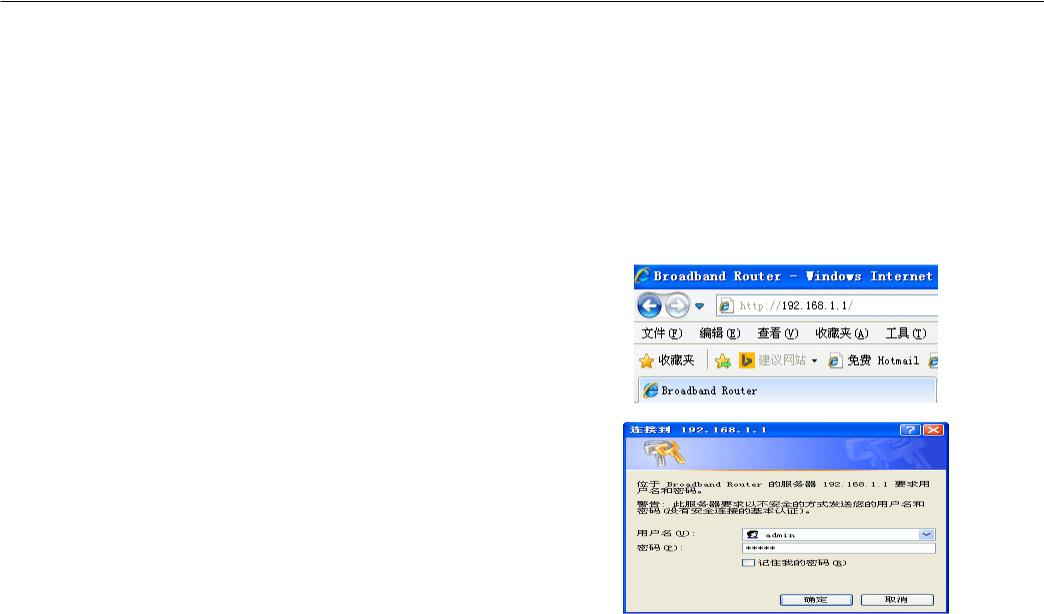
To access the configuration utility, open a web-browser such as Internet Explorer and enter the IP address of the router (192.168.1.1).
Type “admin” for the User Name and “” in the Password field. If you get a Page Cannot be Displayed error, please refer to the Troubleshooting section for assistance.
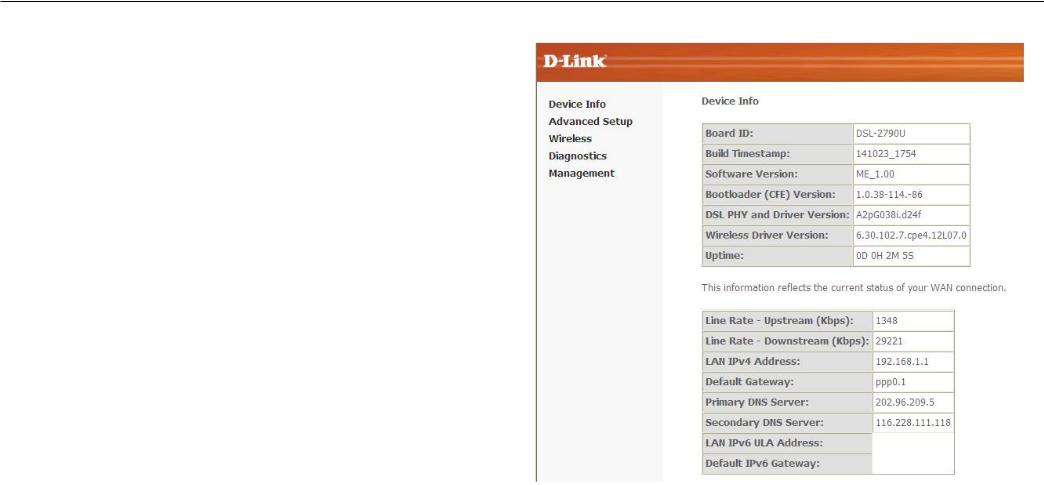
Device Info
To access the Device Info window, click either the Device Info or Summary button in the Device Info directory. The following page opens:
Configuration
Configuration
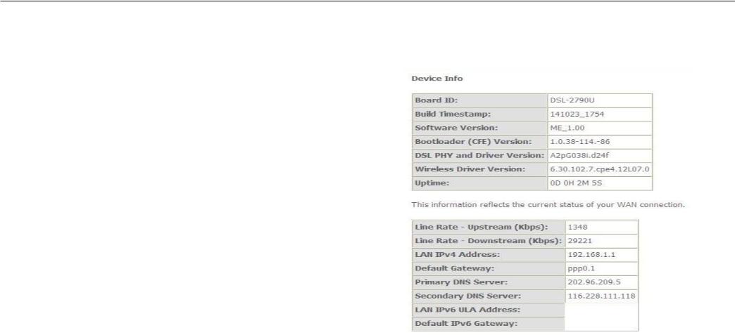
Summary
To access the Router’s first Summary window, click the Summary button in the Device Info directory.
This window displays the current status of your DSL connection, including the software version, LAN IP address, and DNS server address.
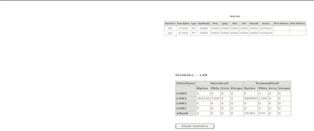
WAN
To access the WAN Info window, click the WAN button in the Device Info directory.
Configuration
This window displays the current status of your WAN connection.
Statistics
To access the Router’s first Statistics window, click the Statistics button in the Device Info directory.
This window displays the Router’s LAN statistics. Click the Reset Statistics button to refresh these statistics.
Configuration
This window displays the Router’s WAN statistics. Click the Reset Statistics button to refresh these statistics.
This window displays the Router’s XTM statistics. Click the Reset button to refresh these statistics.

Configuration
This window displays the Router’s xDSL statistics. Click the Reset Statistics button to refresh these statistics.
Click the xDSL BER Test button to access the ADSL Bit Error Rate Test window displayed below:
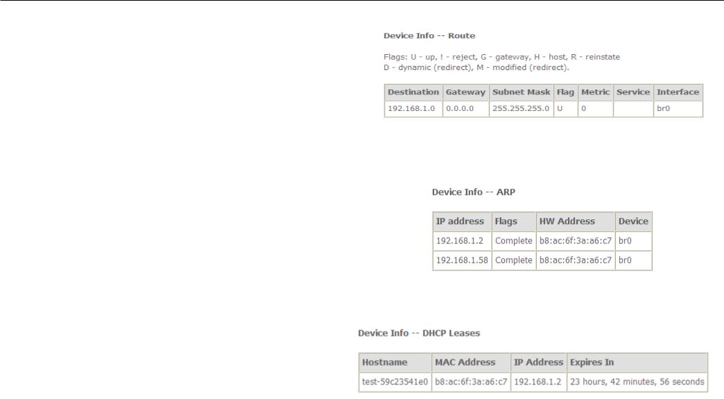
Route
To access the Device Info – Route window, click the Route button in the Device Info directory.
Configuration
This read-only window displays routing info.
ARP
To access the Device Info – ARP window, click the ARP button in the Device Info directory.
This read-only window displays Address Resolution Protocol info.
DHCP
To access the Device Info – DHCP Leases window, click the DHCP button in the Device Info directory. This read-only window displays DHCP lease info.
Advanced Setup
This chapter include the more advanced features used for network management and security as well as administrative tools to manage the Router, view status and other information used to examine performance and for troubleshooting.

Configuration
Layer2 Interface
To access the DSL ATM Interface Configuration window, click the ATM Interface button in the Layer2 Interface directory.
This window is used to configure the ATM interface. You can add and delete ATM interface on this window.
If you are setting up the ATM interface for the first time, click the Add button.
ATM Interface
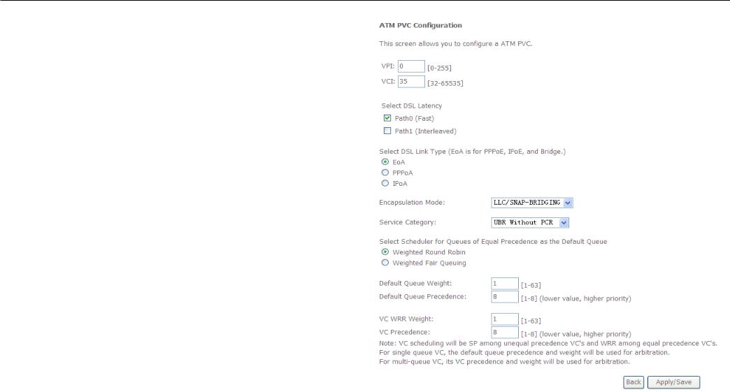
Configuration
The ATM PVC Configuration window allows you to set up ATM PVC configuration. Enter Virtual Path Identifier,and Virtual Channel Identifier. The VPI and VCI values should be provided by your ISP. This window also allows you to select DSL Link Type, PPPoA IpoA and EoA (EoA is for PPPoE, IPoE, and Bridge)
Use the drop-down menu to select the desired Encapsulation Mode..
Click the Apply / Save button to Save.
To access the ETH WAN Interface Configuration window, click the ETH Interface button in the Layer2 Interface directory.
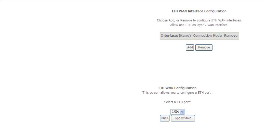
Configuration
This window is used to configure the ETH interface. You can add and delete ETH interface on this window.
If you are setting up theETH interface for the first time, click the Add button.
ETH Interface
The ETH PVC Configuration window allows you to set up ETH WAN configuration. This screen allows you to configure a ETH port.Select a ETH port.Select Connection Mode.
Click the Apply / Save button to Save.
WAN Service
To access the Wide Area Network (WAN) Service Setup window, click the WAN Service button in the Advanced Setup directory.
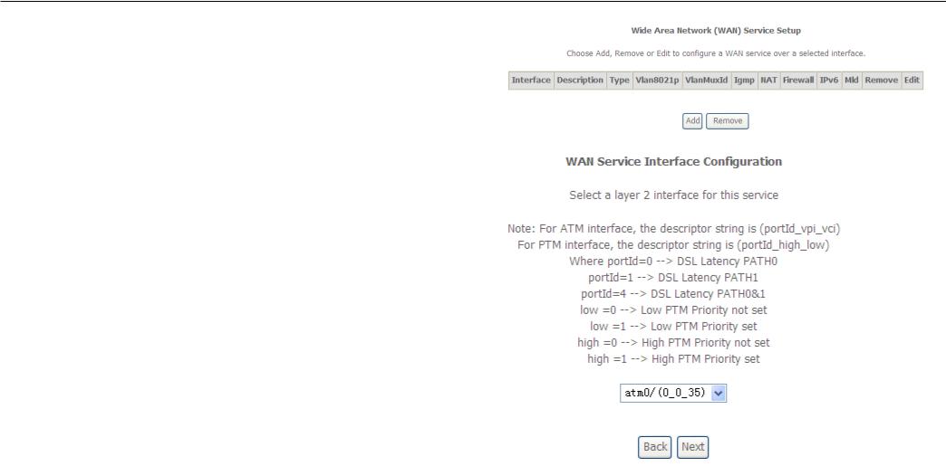
Configuration
This window is used to configure the WAN interface. You can add and delete WAN interface on this window.
If you are setting up the WAN interface for the first time, click the Add button.
The WAN Service Interface Configuration Configuration window allows select a layer 2 interface for this service. Click the Next button to continue.
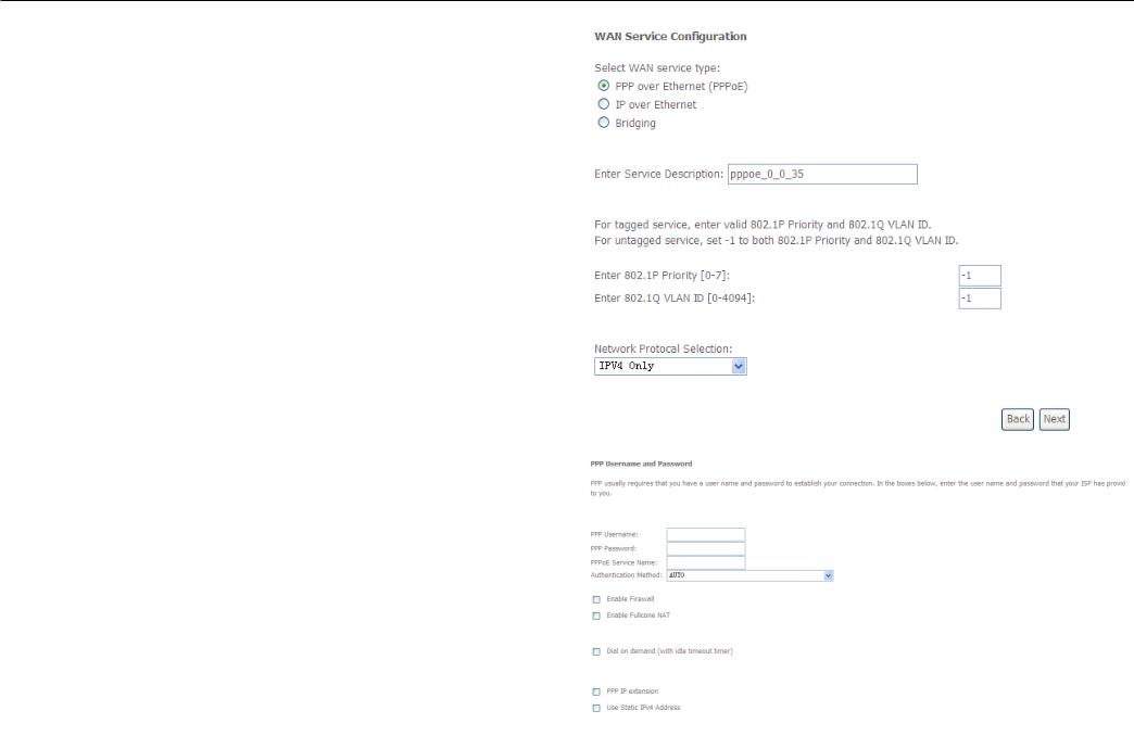
Configuration
This window allows you to select the appropriate connection type. The choices include PPP over ATM (PPPoA), PPP over Ethernet (PPPoE), IP over Ethernet (IpoE), IP over ATM (IPoA), and Bridging.
WAN Service Configuration – PPPoE
Click the PPP over Ethernet (PPPoE) radio button on this window. This window also allows you to use the drop-down menu to enable IPv6 service. Click the Next button to continue.
WAN Service Configuration – PPPoE
This window allows you to set the username and the password for your PPP connection. This information is obtained from your ISP. Additional settings on this window will also depend on your ISP. And You can input 2nd ip on this page. Click the Next button to continue.

Configuration
WAN Service Configuration – PPPoE
Default gateway interface list can have multiple WAN interfaces served as system default gateways but only one will be used according to the priority with the first being the higest and the last one the lowest priority if the WAN interface is connected. Priority order can be changed by removing all and adding them back in again. Click the Next button to continue.
WAN Service Configuration – PPPoE
Select DNS Server Interface from available WAN interfaces OR enter static DNS server IP addresses for the system. In ATM mode, if only a single PVC with IPoA or static IPoE protocol is configured, Static DNS server IP addresses must be entered.
DNS Server Interfaces can have multiple WAN interfaces served as system dns servers but only one will be used according to the priority with the first being the higest and the last one the lowest priority if the WAN interface is connected. Priority order can be changed by removing all and adding them back in again. Click the Next button to continue

Configuration
WAN Service Configuration – PPPoE
This summary window allows you to confirm the settings you have just made. Click the Apply / Save button to save your new PPP over Ethernet settings and restart the Router.
 Loading...