


D-Link DSL-2750E
Wireless N 30 0 ADSL2+ Modem Router
User Manual
RECYCLABLE
2013/0 /184
Ver. 1.00

DSL2750E User Manual
Contents
1 |
Introduction ........................................................................................................ |
|
1 |
|
|
1.1 |
Packing List ........................................................................................... |
1 |
|
|
1.2 |
Safety Precautions ................................................................................ |
1 |
|
|
1.3 |
LEDs and Interfaces.............................................................................. |
2 |
|
|
1.4 |
System Requirements ........................................................................... |
4 |
|
|
1.5 |
Features ................................................................................................ |
4 |
|
2 |
Hardware Installation ......................................................................................... |
6 |
||
|
2.1 |
DSL Uplink Connection ......................................................................... |
6 |
|
3 |
Web Configuration ............................................................................................. |
7 |
||
|
3.1 |
Accessing the Device ............................................................................ |
7 |
|
|
3.2 |
Setup ..................................................................................................... |
|
7 |
|
|
3.2.1 |
Wizard......................................................................................... |
7 |
|
|
3.2.2 |
Internet Setup ........................................................................... |
12 |
|
|
3.2.3 |
Wireless.................................................................................... |
18 |
|
|
3.2.4 |
Local Network........................................................................... |
24 |
|
|
3.2.5 |
LAN IPv6................................................................................... |
27 |
|
|
3.2.6 |
Time and Date .......................................................................... |
28 |
|
|
3.2.7 |
Logout....................................................................................... |
29 |
|
3.3 |
Advanced............................................................................................. |
29 |
|
|
|
3.3.1 |
Advanced Wireless................................................................... |
29 |
|
|
3.3.2 |
Port Forwarding ........................................................................ |
36 |
|
|
3.3.3 |
DMZ.......................................................................................... |
37 |
|
|
3.3.4 |
SAMBA ..................................................................................... |
38 |
|
|
3.3.5 |
3G Configuration....................................................................... |
39 |
|
|
3.3.6 |
Parental Control........................................................................ |
47 |
|
|
3.3.7 |
Filtering Options........................................................................ |
51 |
|
|
3.3.8 |
QoS Configuration .................................................................... |
56 |
|
|
3.3.9 |
Firewall Settings ....................................................................... |
60 |
|
|
3.3.10 |
DNS..................................................................................... |
60 |
|
|
3.3.11 |
Dynamic DNS...................................................................... |
61 |
|
|
3.3.12 |
Network Tools...................................................................... |
63 |
|
|
3.3.13 |
Routing................................................................................ |
70 |
|
|
3.3.14 |
Schedules............................................................................ |
74 |
|
|
3.3.15 |
NAT ..................................................................................... |
75 |
i

DSL2750E User Manual
|
3.3.16 |
FTPD Setting ....................................................................... |
77 |
|
3.3.17 |
FTPD Account ..................................................................... |
77 |
|
3.3.18 |
IP Tunnel ............................................................................. |
78 |
|
3.3.19 |
Logout ................................................................................. |
82 |
3.4 |
Management........................................................................................ |
83 |
|
|
3.4.1 |
Global IPv6 ............................................................................... |
83 |
|
3.4.2 |
System Management ................................................................ |
83 |
|
3.4.3 |
Firmware Update ...................................................................... |
85 |
|
3.4.4 |
Access Controls ........................................................................ |
86 |
|
3.4.5 |
Diagnosis .................................................................................. |
89 |
|
3.4.6 |
Log Configuration ..................................................................... |
92 |
|
3.4.7 |
Logout ....................................................................................... |
93 |
3.5 |
Status |
................................................................................................... |
94 |
|
3.5.1 |
Device Info ................................................................................ |
94 |
|
3.5.2 |
Wireless Clients ........................................................................ |
95 |
|
3.5.3 ............................................................................ |
DHCP Clients |
95 |
|
3.5.4 ................................................................................ |
IPv6 Status |
95 |
|
3.5.5 .......................................................................................... |
Logs |
96 |
|
3.5.6 ............................................................................. |
Firewall Logs |
97 |
|
3.5.7 .................................................................................... |
Statistics |
97 |
|
3.5.8 ................................................................................. |
Route Info |
98 |
|
3.5.9 ....................................................................................... |
Logout |
99 |
3.6 |
Help ..................................................................................................... |
|
99 |
ii

DSL2750E User Manua l
1 Introduction
The DSL-2750E supports multiple line modes. |
four 10/100With base-T Ethernet |
interfaces at the user end, the device provide |
speed ADSLs broadbandhigh- |
connection to the Internet or Intranet for high-end users like net bars and office users. It provides high performance access to the Internet with a
rate of 24 Mbps and |
an upstrrateamof 1 Mbps. It supports 3G WAN, 3G |
||
backup, Samba for |
USB storage and IPV6. |
|
|
The device suppor |
ts WLAN access |
, such as WLANdeviceAP or,theWLANto |
|
I nternet. It complies with specifications of IEEE 802.11 |
, 802.11b/g/n, WEP, WPA, |
||
and WPA2 security. |
|
|
|
1.1 Packing List
1 x DSL-2750E
1 x external splitter
1 x power adapter
|
1 x telephone cables |
-11) |
(RJ |
|
1 x Ethernet cable |
-45) |
(RJ |
1 xQIG
1 X CD
1.2 |
Safety Precautions |
|
|
Take the following instruction |
even sttotheprdevice from risks and damage |
||
caused by fire electricor power: |
|
|
|
|
Use the type of power |
ed in the volumemark label. |
|
|
Use the power adapter in the product kage. |
pac |
|
|
Pay attention to the power load of the outlet or prolonged lines. An |
||
|
overburden power outlet or damaged lines or plugs may cause electric |
||
|
shock or fire accidents. Check the power cords regularly. If you find any |
||
|
damage, replace it at once. |
|
|
|
Proper space left for heat |
ation is necedissaryip to avoid damage |
|
caused by overheating to the device. The long and thin holes on the
1
DSL2750E User Manual
|
are designed for heat |
ation todissipensure that the device works normally. |
|
|
Do not cover these heat |
ation holediss.ip |
|
|
Do not put this device close to a heat source |
under a high temperatureor |
|
|
occurs. Keep the device |
away |
from direct sunshine. |
Do not put this device close to an overdamp or watery place. Do not spill fluid on this device.
Do not connect this device to a PC or electronic product unless instructed
by our customer engineer or your broadband provider. Wrong connection may cause power or fire risk.
Do not place this device on an unstable surface or support.
1.3 LEDs and Interfaces
Note:
The figures in this document are for reference only.
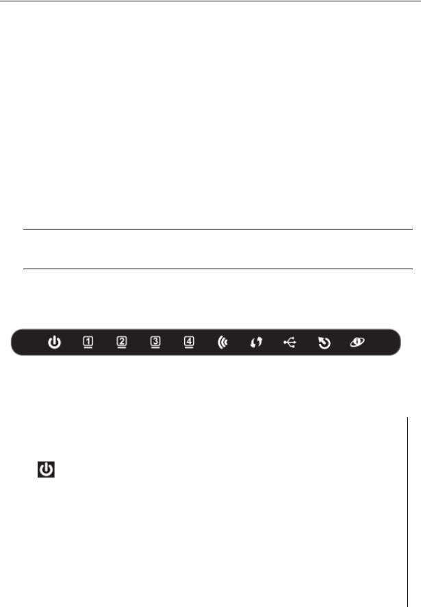
Front P anel
Figure 1 Front panel
The following table describes the LEDs of the device.
LED |
Color |
Status |
|
Description |
|
|
|
||
|
|
Off |
The power is off. |
|
|
|
|
||
|
Green |
On |
The power is on and the |
ialization isinit |
|
||||
|
|
normal. |
|
|
|
|
|
||
Power |
|
|
|
|
|
|
|
||
Red |
On |
The device |
isiatinginit . |
|
|
|
|||
|
|
|
|
||||||
|
Blinks |
The |
firmware |
is |
upgrading. |
|
|
||
|
|
|
|
||||||
|
|
Off |
No LAN link. |
|
|
|
|
|
|
LAN |
|
Blinks |
Data |
is being |
transmitted |
through |
the |
|
|
Green |
LAN interface. |
|
|
|
|
|
|||
1/2/3/4 |
|
|
|
|
|
|
|||
|
On |
The |
connection of |
LAN |
interface |
is |
|
||
|
|
|
|||||||
|
|
normal. |
|
|
|
|
|
||
|
|
|
|
|
|
|
|
||
2
DSL2750E User Manual
|
LED |
Color |
Status |
|
Description |
|
|
|
|
|
|
Blinks |
D ata is |
transmitted |
through the WLAN |
|
|
|
|
|
interface. |
|
|
|
|
|
|
|
|
|
|
|
|
|
|
|
WLAN |
Green |
On |
The connection of |
WLAN interface is |
|
|
|
|
normal. |
|
|
|
|
|||
|
|
|
|
|
|
|
|
|
|
|
|
Off |
The WLAN connection is not established. |
|
|
||
|
|
|
|
|
|
|
||
|
|
|
Blinks |
WPS negotiation is enabled, waiting for |
|
|
||
|
|
|
the clients. |
|
|
|
||
|
|
Blue |
|
|
|
|
||
|
WPS |
Off |
WPS negotiation is not enabled on the |
|
|
|||
|
|
|
|
|||||
|
|
|
device. |
|
|
|
|
|
|
|
|
|
|
|
|
|
|
|
|
|
On |
The connection of 3G or USB flash disk |
|
|
||
|
|
|
has been established. |
|
|
|||
|
|
|
|
|
|
|||
|
USB |
Green |
Blinking |
Data is being transmitted. |
|
|
||
|
|
Off |
The connection of 3G or USB flash disk |
|
|
|||
|
|
|
|
|
||||
|
|
|
is not established. |
|
|
|
||
|
|
|
|
|
|
|
||
|
|
|
Off |
Initial self-test is failed. |
|
|
||
|
|
Green |
Blinks |
The device is detecting itself. |
|
|
||
|
DSL |
On |
Initial self |
-t est of the unit has passed |
|
an |
||
|
|
|
||||||
|
|
|
is ready. |
|
|
|
|
|
|
|
|
|
|
|
|
|
|
|
|
|
|
The device is under the Bridge mode |
, |
|||
|
|
|
Off |
DSL connection is not present, or the |
|
|
||
|
|
Green |
|
power is off. |
|
|
|
|
|
|
Blinks |
Internet data is being transmitted in the |
|
|
|||
|
|
|
|
|
||||
|
Internet |
|
|
routing mode. |
|
|
|
|
|
|
On |
The IP is connected. |
|
|
|
||
|
|
|
|
|
|
|||
|
|
Red |
On |
The device is attempted to become IP |
|
|
||
|
|
connected, but failed. |
|
|
||||
|
|
|
|
|
|
|||
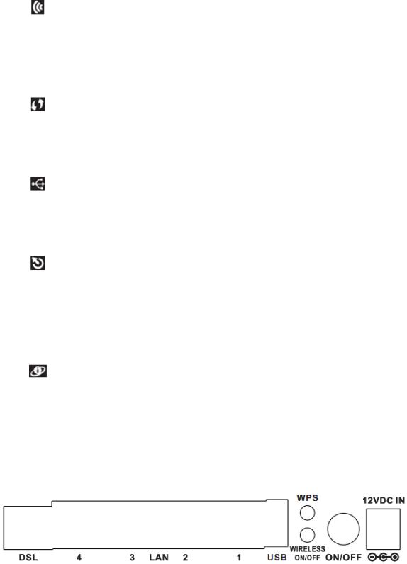
Rear P anel
Figure 2 Rear panel
3

DSL2750E User Manual
The following |
describestable the interface of the device. |
|
|
|||
Interface/Button |
|
|
Description |
|
|
|
DSL |
|
RJ-11 interface that connects to the telephone set through |
|
|||
|
the telephone cable. |
|
|
|
||
|
|
|
|
|
||
LAN4/3/2/1 |
|
Ethernet RJ-45 interfaces that connect to the Ethernet |
|
|||
|
interfaces of computers or Ethernet devices. |
|
|
|||
|
|
|
|
|||
USB |
|
USB port, for connecting the 3G network card or other USB |
|
|||
|
storage devices. |
|
|
|
||
|
|
|
|
|
||
WPS |
|
Press the button for 1 second to enable WPS function. |
|
|||
|
|
|
|
|
|
|
WIR ELESS |
|
Press the button silently to enable WLAN function. |
|
|
||
ON/OFF |
|
|
|
|||
|
|
|
|
|
|
|
ON/OFF |
|
Power on |
ffortheo device. |
|
|
|
|
|
|
|
|
||
12V DC IN |
|
Interface that connects to the power adapter. The |
power |
|
||
|
adapter output is: 12V DC 1A. |
|
|
|
||
|
|
|
|
|
||
|
|
|
|
|||
Reset (on the |
|
Reset to the factory defaults. To restore factory defaults, |
|
|||
|
keep the device powered on and push a paper clip into the |
|
||||
bottom case) |
|
|
||||
|
hole. Press down the button |
second andfor 1 |
then release. |
|||
|
|
|||||
|
|
|
|
|
|
|
1.4 System Requirements
|
A 10 baseT/100BaseT Ethernet card |
is installed on your PC. |
A hub or switch (attached to several PCs through one of Ethernet interfaces on the device)
Operating system: Windows Vista, Windows 7, Windows 98SE, Windows 2000, Windows ME or Windows XP
Internet Explorer V5.0 or higher, Netscape V4.0 or higher, or Firefox 1.5 or higher
1.5 Feature s
Various line modes
External PPPoE dial-up access
Internal PPPoE and PPPoA dial-up access
Leased line mode
1483B, 1483R, and MER access
4

DSL2750E User Manual
Multiple PVCs (eight at most) and these PVCs can be isolated from each other
A single PVC with multiple sessions
Multiple PVCs with multiple sessions
Binding of portswith PVCs
802.1Q and 802.1P protocol
DHCP server
NAT and NAPT
Static route
Firmware upgrade: Web, TFTP, FTP
Reset to the factory defaults
DNS relay
Virtual server
DMZ
|
Two-level passwords and user |
names |
|
|
Web user inte |
rface |
|
Telnet CLI
System status display
PPP session PAP and CHAP
IP filter
IP QoS
Remote access control
Line connection status test
Remote management elnet and HTTP)(t
Backup and restoration of configuration file
Ethernet interface supports crossover detection, auto-correction and polarity correction
UPnP
IPV6
3G WANand 3G Backup
|
Samba for |
storageUSB |
5
DSL2750E User Manua |
l |
2Hardware Installation
2.1DSL Uplink Connection
Step 1 |
Connect the |
portDSLof the device and the |
Modem |
port of the splitt |
||
|
with a |
telephone cable |
. Connect the phonehonetoportthe of the |
P |
||
|
splitter through a telephone cable. Connect the incoming line to the |
|
||||
|
Line port of the splitter. |
|
|
|
||
|
The splitter has three ports: |
|
|
|
||
|
|
Line: Connect to a wall phone port -11 jack). |
(RJ |
|
||
|
|
Modem: Connect to the DSL port of the device. |
|
|
||
|
|
Phone: Connect to a telephone set. |
|
|
||
Step 2 |
Connect a |
portLANof the device to the network card of the PC |
|
|||
|
through an Ethernet cable (MDI/MDIX). |
|
|
|||
Note:
Use twisted - pair cables to connect the deviceHubto aor switch.
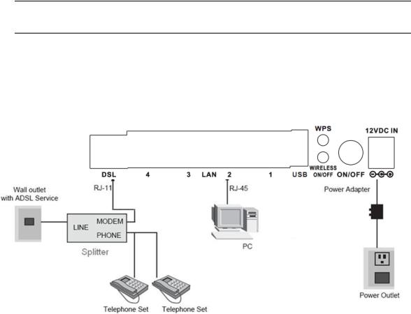
Step 3 Plug one end of the power adapter to the wall outlet and the other end to the Powerport of the device.
Figure 3 displays the application diagram for the connection of the device, PC, splitter and telephone sets, when no telephone set is placed before the splitter.
Figure 3 Connection diagram
6
DSL2750E User Manua l
3 |
Web Configuration |
|
|
|
|
This chapter describes how to configure the device by using the |
Web-based |
||||
configuration utility. |
|
|
|
|
|
3.1 |
Accessing the Device |
|
|
|
|
The following is the detailed description of accesing the device for the first time. |
|||||
Step 1 Open the Internet Explorer (IE) |
browser and http://192enter |
.168.1.1. |
|||
|
|
|
|||
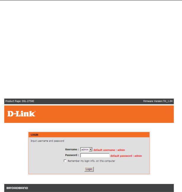
Step 2 The Login page shown in the following figure appears. Ent |
|||||
|
name and password and click |
Login . |
|
|
|
|
The user name and password of the super user are |
|
|
||
|
admin . |
|
|
|
|
3.2Setup
3.2.1Wizard
After login, the Wizardpage under Setup tab appears.
Wizard enables fast and accurate configuration of Internet connection and other important parameters. The following sections describe configuration parameters. When subscribing to a broadband service, you should be aware of the method
by which you are connected to the Internet. Your physical WAN device can be
7
DSL2750E User Manual
Ethernet, DSL, or both. Technical information |
the |
properties of |
aboutyour |
||
Internet connection is provided by your Internet |
service |
p |
rovider |
(ISP). For |
|
example, your ISP should inform you whether you are connected to the Internet |
|||||
using a static or dynamic IP address, or |
protocol, such asthePPPo A or PPPoE, |
||||
that you use to communicate over the Internet. |
|
|
|
|
|
Click Setup Wizard |
. The page shown in the following figure appears. |
There are 5 steps to configu the device. Clickre |
to continueNext . |
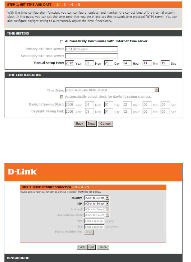
Step 1 Set the time and date. |
|
8
DSL2750E User Manual
Step 2 Configure the Internet connection.
Click Next after time and date setting and the following page appears. page, you can set the internet connection.
9
DSL2750E User Manual
The following table describes the fields in this page. |
|
|
|||
|
Field |
|
Description |
|
|
|
Country |
Select the country you located from the drop-down list. |
|
||
|
ISP |
Select the ISP you subscribed the internet service |
|
||
|
from. |
|
|
|
|
|
|
|
|
|
|
|
Protocol |
Select the protocol you subscribed from your ISP. |
|
||
|
Encapsulation |
Select the method of encapsulation provided |
by you |
||
|
Mode |
ISP. You can select LLC or VCMUX. |
|
||
|
|
VPI: The virtual path between two points in an ATM |
|
||
|
|
network. I |
ts validluevais from |
0 to 255 . |
|
|
PVC Settings |
VCI : The virtual channel between two pointsnian ATM |
|
||
|
|
network, ranging from |
32(0 toto3165535is reserved |
|
|
|
|
for local management of ATM traffic). |
|
||
Note :
Different protocol requires entering different information. You can fill in the entries according to what your ISP provides you.
Click Next. The page shown in the following page appears.
10

DSL2750E User Manual
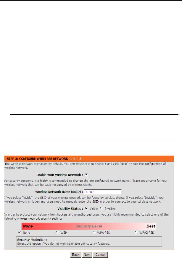
Step 3 Configure the wireless network. Enter the information and click |
to |
Next |
go to the next step. |
|
|
Step 4 Change or create the password of an account. Click |
to go to the |
Next |
next step. |
|
|
11
DSL2750E User Manual
Step 5 Click Apply to save the settings.
Note :
In each step of the Wizard page |
Back, youtocanreviewclickor |
|
modify the previous |
settings.Click Cancel to exit |
thewizard page. |
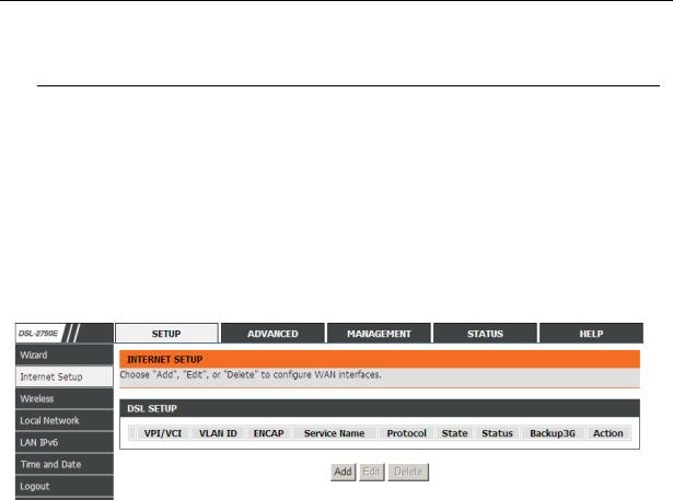
3.2.2Internet Setup
Choose Setup Internet> |
Setup |
. The page shownfollowing figuretheappears. |
In this page, you can configure the |
WAN interface of the device. |
|
12
DSL2750E User Manual
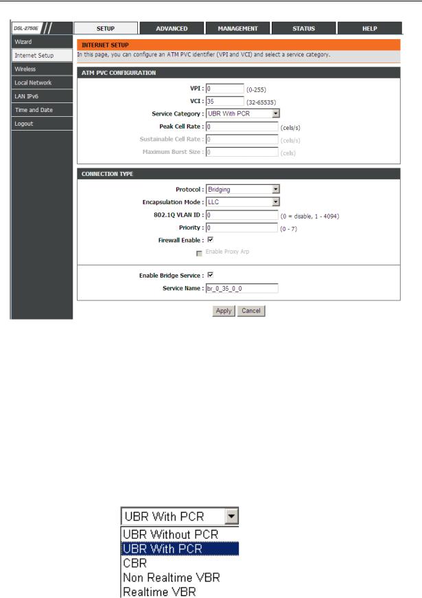
Click Add and the page shown in the following figure appears.
The following table describes the parameters in this page.
Field |
|
|
Description |
||
|
VPI: The virtual path between two points in an ATM |
||||
|
network. I |
ts validluevais from |
0 to 255 . |
||
PVC Settings |
|
VCI : The virtual channel between two pointsnian ATM |
|||
|
network, ranging from |
32(0 toto3165535is reserved |
|||
|
|
||||
|
|
for local management of ATM traffic). |
|||
|
|
The values of VPI and VCI are provided by your ISP. |
|||
|
|
You can select from the drop-down list. |
|||
Service |
|
|
|
|
|
|
|
|
|
|
|
Category |
|
|
|
|
|
|
|
|
|
|
|
|
|
|
|
|
|
13
DSL2750E User Manual
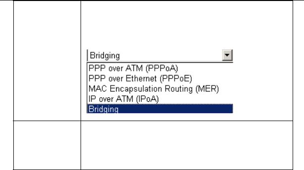
Field |
|
Description |
|
|
|
Selected the protocol you subscribed from your ISP. It |
|
|
|
displays the protocol type used for this WAN connection. |
|
Protocol |
|
|
|
|
|
|
|
|
|
|
|
Encapsulation |
Select the method of encapsulation |
by your ISPprovided. |
|
Mode |
You can select LLC or VCMUX. |
|
|
802.1Q VLAN |
You can enable or disable this function. The value ranges |
||
ID |
from 1 to 4094 . 0Valuemeans to disable this function. |
||
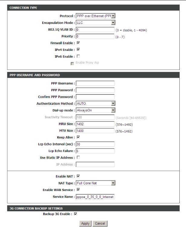
- PPPoE |
or PPPoA |
|
|
I f the protocol is selected to be |
PPP over Ethernetor PPP(PPPover ATM |
oE) |
|
(PPPoA), the following page appears. |
|
|
|
14
DSL2750E User Manual
The following table describes the parameters of this page
Field |
Description |
PPP Username |
The correct user name provided by your ISP. |
|
|
|
15 |

DSL2750E User Manual
|
Field |
|
Description |
|
|
|
|
|
PPP Password |
The correct password provided by your ISP |
|
|
|
||
|
Authentication |
To authenticate whether the PPP username and |
|
|
|||
|
password are correct. The value can be AUTO, |
PAP, |
|
|
|||
|
Method |
|
|
||||
|
CHAP or MS-CHAP. Usually, you can |
|
select AUTO. |
||||
|
|
|
|||||
|
|
AlwaysOn: If you select it, the |
system |
|
|||
|
|
automatically establishes a connection. If |
|||||
|
|
network is |
disconnected |
becauseofext rnal |
|||
|
|
factors when you are using the Internet access |
|||||
|
|
service, the system tries connection every certain |
|||||
|
|
time (for example, 10 seconds) until the connection |
|||||
|
|
is established. If you pay for Internet access in the |
|||||
|
|
mont hly fee mode, you are recommended to use |
|||||
|
|
this connection mode. |
|
|
|
|
|
|
Dial-up mode |
OnDemand: |
If you select it, |
the |
system |
||
|
automatically establishes a connection when a |
||||||
|
|
||||||
|
|
network access request from the LAN is received. If |
|||||
|
|
no network access request is sent from the LAN |
|||||
|
|
within the set time of Idle Timeout |
|
, the system |
|||
|
|
automatically interrupts the connection. If you pay |
|||||
|
|
for Internet access by time, you are recommended |
|||||
|
|
to use this connection mode, which effectively |
|||||
|
|
saves the expense of Internet access. |
|
|
|
|
|
|
|
Manual: If you select it, you need to manually set |
|||||
|
|
dialup connection after startup. |
|
|
|
|
|
|
MRU Size |
You can keep it as default. |
|
|
|
|
|
|
|
If this function is disabled, the modem obtains an IP |
|||||
|
Use Static IP |
address assigned by an uplink equipment such as |
|||||
|
BAS , through PPPoE dial-up. If this function is |
||||||
|
Address |
||||||
|
enabled, the modem uses this IP address as the WAN |
||||||
|
|
||||||
|
|
IP address. |
|
|
|
|
|
|
|
NAT is one where all requests from the same internal |
|||||
|
|
IP address and port are mapped to the same external |
|||||
|
Enable NAT |
IP address and port. Furthermore, any external host |
|||||
|
|
can send a |
tpacketo the internal host, by sending a |
||||
|
|
packet to the mapped external address. |
|
|
|
|
|
|
|
|
16 |
|
|
|
|
DSL2750E User Manual
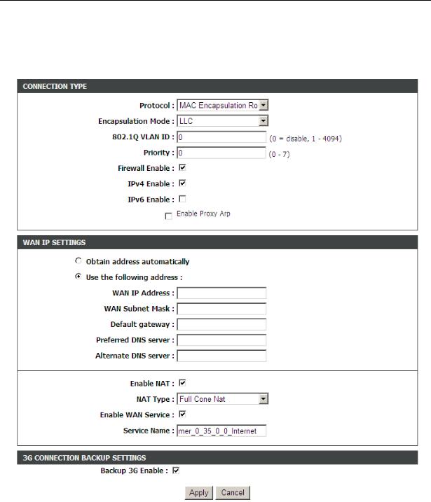
- MAC Encapsulation Routing /IPoA
C hoose Protocol to beMAC Encapsulation Routing or IP over ATM (IPoA), and the following page appears.
The following table describes the parameters of this page
Field |
Description |
WAN IP |
Enter the WAN IP address provided by the ISP. |
Address |
|
WAN Subnet |
Enter the WAN subnet mask provided by the ISP. It |
|
17 |
DSL2750E User Manual
|
Field |
Description |
|
|
Mask |
varies depending on the network type. It is usually |
|
|
|
255.255.255.0 |
|
|
Default |
Enter the IP address of the gateway provided by the |
|
|
Gateway |
ISP. It is the IP address used for connecting to the ISP. |
|
|
Preferred DNS |
Enter the IP address of the primary DNS server if |
|
|
Server |
necessary |
|
|
Alternate DNS |
If the ISP provides another DNS server, enter the |
|
|
Server |
address of that DNS server. |
|
After setting, click Apply to make the settings take effect.
3.2.3Wireless
This section describes the wireless LAN and basic configuration. A wireless LAN can be as simple as t o computersw with wireless LAN cards communicating in a pear-to-pear network or as complex as a number of computers with wireless LAN
cards communicating through |
p oints whichaccessbridge network traffic to wired |
|
LAN. |
|
|
Choose Setup Wireless> |
. The |
Wirelpagesshown in the following figure |
appears. |
|
|
3.2.3.1 |
Wireless Basic |
s |
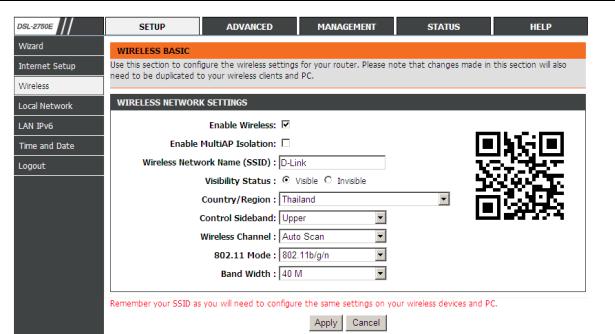
In the Wirelesspage, click Wireless Basic The page. shown in the following figure appears. In this page , you canconfigure the parameters of wireless LAN clients that may connect to the device.
18
DSL2750E User Manual
The following table describes the parameters in this page.
Field |
|
Description |
|
|
Enable |
Select this to turn Wi-Fi on. |
|
|
|
Wireless |
|
|
|
|
Enable MultiAP |
Select this to turn MultiAP isolation on. |
|
|
|
Isolation |
|
|
|
|
|
The Wireless Network Name is a unique name that |
|
||
Wireless |
identifies a network. All devices on a network must |
|
||
share the same wireless network name in order to |
|
|||
Network Name |
|
|||
communicate on the network. If you decide to change |
|
|||
(SSID) |
|
|||
the wireless network name from the default setting, |
|
|||
|
|
|||
|
enter your new wireless network name in this field. |
|
||
Visibility Status |
Select |
Visible , the SSID can be detected. Select |
|
|
Invisible, the SSID cannot be detected. |
|
|
||
|
|
|
||
Country |
Select the country you located from the drop-down list. |
|
||
Control |
Choose the channel selection mode as |
or |
Upper |
|
Sideband |
Lower. |
|
|
|
Wireless |
Select the wireless channel from the pull-down menu. |
|
||
Channel |
It is different for different country. |
|
|
|
802.11 Mode |
Select the appropriate 802.11 mode based on the |
|
||
19
DSL2750E User Manual
|
Field |
|
|
Description |
|
|
|
|
|
|
|
wireless clients in your network. It is recommended to |
|
|
|||
|
|
|
keep it as default. |
|
|
|
||
|
Band |
Width |
Select the appropriate band of 20M, 40 |
M 20M/40Mor |
|
|
||
|
according to your subscribed broadband service. |
|
|
|||||
|
|
|
|
|
||||
There is a |
Dimension2- |
Code on the right of the page. his code canT help your |
||||||
cellphone |
connect |
to the wireless network of DSL 2750E |
automatically by - |
|||||
shooting the 2-Dimension code |
the cellphonewith. |
|
|
|
||||
Note:
A cellphone |
can not connect to the wireless network |
unless a |
2- Dimensioncode software is installed on your cellphone |
. |
|
Click Apply to |
savethe settings. |
|
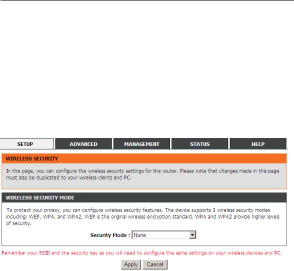
3.2.3.2Wireless Security
In the |
Wirelesspage, click Wireless Security. The page shown in |
thewingfollo |
figure appears. Wireless security is vital to your network to |
prot |
|
communication among wireless stations, access points and wired network. |
|
|
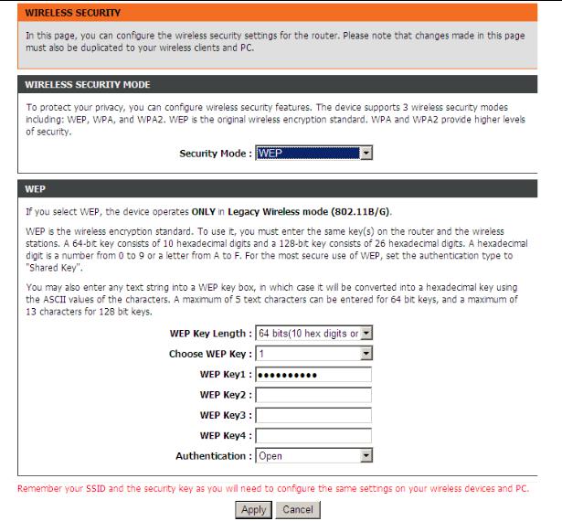
If the Security Mode is set to be |
WEP , the following page appears. |
20
DSL2750E User Manual
The following table describes the parameters of this page.
Field |
|
Description |
|
|
|
||
|
Configure the wireless encryption mode. You can |
||
|
choose |
None, WEP Auto, |
(WPA or WPA2), WPA |
|
2 Only or WPA Only. |
|
|
|
Wired |
equivalent privacy (WEP) encrypts |
|
Security Mode |
data frames before transmitting over the wireless |
||
|
network. |
|
|
|
Wi Fi- |
protected a |
(WPA)ccess is a subset of |
|
the IEEE802.11i security specification draft. |
||
|
WPA2 Mixed is the collection of WPA and |
||
21
DSL2750E User Manual
|
Field |
|
Description |
|
|
|
|
|
|
|
|
WPA2 encryption modes. The wireless client |
|
|
|
|
establishes the connection between the modem |
|
|
|
|
through WPA or WPA2. |
|
|
|
|
Key differences between WPA and WEP are user |
|
|
|
|
authentication and improved data encryption. |
|
|
|
WEP Key Length |
Choose the WEP key length. You can Choose |
|
|
|
64-bit or 128-bit. |
|
|
|
|
|
|
|
|
|
Choose WEP Key |
Choose the index of WEP Key. You can choose |
|
|
|
Key 1, 2 , 3 or |
4 . |
|
|
|
|
|
||
|
|
The Encryption keys are used to encrypt the data. |
|
|
|
WEP Key 1/2/3/4 |
Both the modem and wireless stations must use |
|
|
|
the same encryption key for data transmission. |
|
||
|
|
|
||
|
|
The default key 1 is 1234567890. |
|
|
|
|
There are 2 authentications in WEP encryption. |
|
|
|
Authentication |
Open and Share key. Both authentications |
|
|
|
support WEP encryption. ut the messageB header |
|
||
|
|
|
||
|
|
is different in wireless broadcast. |
|
|
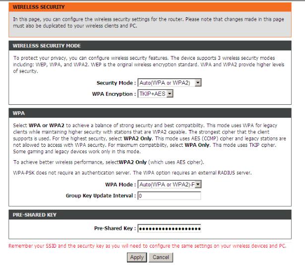
I f the Security Mode is set to beAuto (WPA or WPA2), WPA2 only, or WPA only, the following page appears.
22
DSL2750E User Manual
The above figure shows the when the |
|
is setSecurityas AutMode(WPA or |
|||||
WPA2). The following table describes the parameters in this page. |
|
|
|||||
|
Field |
|
|
Description |
|
|
|
|
WPA |
You can select WPA encryption to be AES |
or |
|
|||
|
Encryption |
TKIP+AES. |
|
|
|
|
|
|
|
|
Select Auto (WPA or |
WPA2)-PSK, |
enter the |
|
|
|
|
pre-shared key in the |
-SharedPreKey |
field. |
|
||
|
|
|
Select Auto |
(WPA |
or WPA2) |
|
-Enterprise |
|
WPA Mode |
(RADIUS), enter the port, IP address, and password of |
|
||||
|
|
the Radius server. You need to enter the username |
|
||||
|
|
and password provided by the Radius server when the |
|
||||
|
|
wireless client connects the modem. |
|
|
|||
|
Group Key |
When WPA encryption is applied, messages sent are |
|
||||
23
DSL2750E User Manual
|
Field |
Description |
|
|
Update Interval |
encrypted with a password. For higher security, WPA |
|
|
|
password is updated periodically. This value is the |
|
|
|
update interval of the WPA password. |
|
Click Apply to savethe settings.
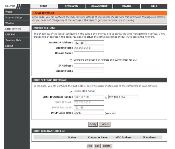
3.2.4Local Network
You can configure the LAN IP address according to the actual application. The preset IP address is 192.168.1.1. You can use the default settings and DHCP
service to |
managetheIP settings for the private network. The IP address of |
the |
||||
device is the base address used for DHCP. To use the |
deviceforDHCP on your |
|||||
LAN, the IP address pool used for DHCP must be compatible with the IP address |
||||||
of the device. The IP address available in the DHCP IP address pool change |
||||||
automatically if you change the IP address of the |
. |
device |
||||
You can also enable the secondary LAN IP address. The two LAN IP addresses |
||||||
must be in different networks. |
|
|
|
|
||
Choose Setup |
Local> |
Network |
. The |
LocalpagNetworkshown |
in |
the |
following figure appears.
24
DSL2750E User Manual
The following table describes the parameters in this page
Field |
|
Description |
|
|
|
Enter the IP address of LAN interface. It is |
|
||
Router IP Address |
recommended to use an address from a block that is |
|||
reserved for private use. This address block is |
||||
|
||||
|
192.168.1.1- 192.168.255.254. |
|
||
Subnet Mask |
Enter the subnet mask of LAN interface. The range of |
|||
subnet mask is from |
255255.255.255.0.2550.254-. |
|||
|
||||
|
Enter the domain name if you know. If you leave this |
|||
|
blank, the domain name obtained by DHCP from the |
|||
Domin Name |
ISP is used. You must enter host name |
(system |
||
|
name) on each individual PC. The domain name can |
|||
|
be assigned from the router through the DHCP |
|||
25
DSL2750E User Manual
|
Field |
Description |
|
|
|
|
|
server. |
|
|
|
|
Configure the |
Select it to enable the secondary LAN IP address. |
|
|
|
|
second IP Address |
The two LAN IP addresses must be in the different |
|
|
|
|
and Subnet Mask |
network. |
|
|
|
|
for LAN |
|
|
|
|
|
|
Enable the router to assign IP addresses, IP default |
|
|
|
|
Enable DHCP |
gateway and DNS Servers to |
Windows95,thehost in |
|
|
|
Server |
Windows NT and other operation systems that |
|
||
|
|
support the DHCP client. |
|
|
|
|
DHCP IP Address |
It specifies the first IP address |
the IP addressin pool. |
|
|
|
The router assigns IP address that base on the IP |
|
|||
|
Range |
|
|||
|
pool range to the host. |
|
|
|
|
|
|
|
|
|
|
|
|
The lease time determines the period that the host |
|
||
|
DHCP Lease Time |
retains the assigned IP addresses before the |
IP |
||
|
|
addresses change. |
|
|
|
Click Apply to make the settings take effect.
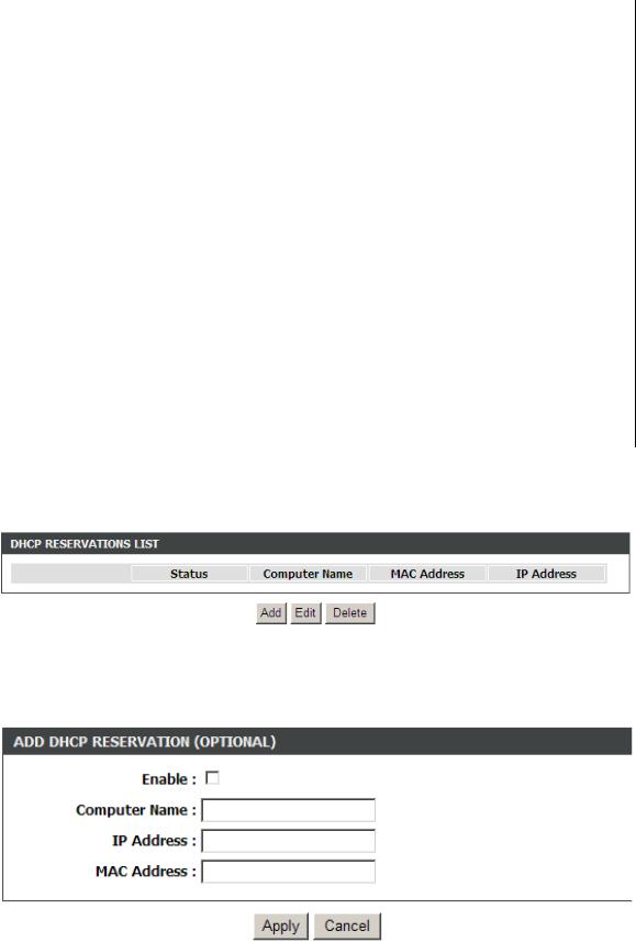
The DHCP RESERVATIONS LISTshown in the following figure appears.
Click Add to add DHCP (optional). The page shown in the following figure appears.
26
DSL2750E User Manual
Select |
Enableto reserve the |
IP address for the designated PC with the |
|
|||
configured MAC address. The |
|
Comhelputers youNameto recognize the PC |
|
|||
with the MAC address, for example, Father’s Laptop. |
Apply to save the |
Click |
||||
settings. |
|
|
|
|
|
|
After the DHCP reservation is saved, the |
DHCPreservations list |
displaysthe |
||||
configuration. |
|
|
|
|
|
|
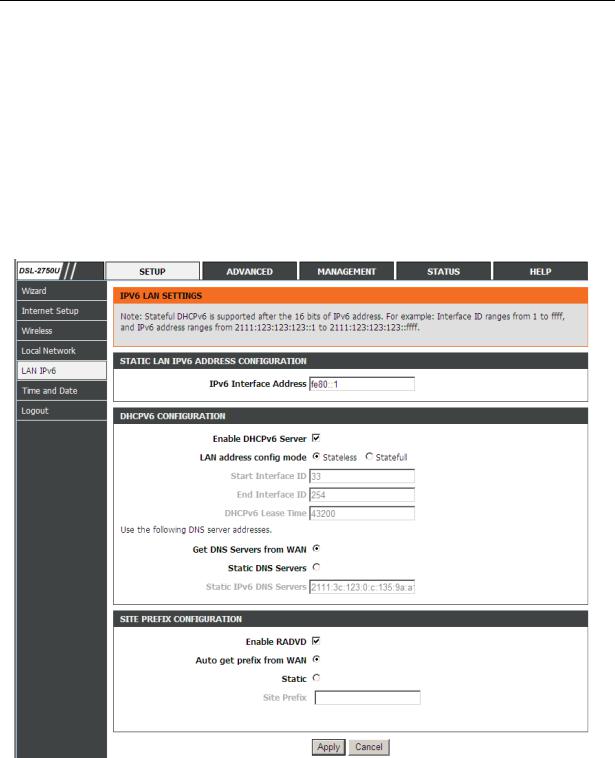
3.2.5LAN IPv6
Choose SetupLAN IPv6> . The page shown in the following figure appears. page allows you to config IPv6 LAN.
The following table describes the parameters of this page.
Field |
Description |
|
|
IPv6 Interface |
The address through which PCs access the |
Address |
gateway. For example, 192.168.1.1. |
|
27 |
 Loading...