


DWL-8710AP
Table of contents
 Loading...
UNIFIED ACCESS POINT
ADMINISTRATOR’S GUIDE
PRODUCT MODEL: DWL-2600AP, DWL-3600AP, DWL-6600AP, DWL-6610AP,
DWL-6700AP, DWL-8600AP, DWL-8610AP, DWL-8710AP
UNIFIED WIRED & WIRELESS ACCESS SYSTEM
RELEASE 6.20
October
2015
© C
OPYRIGHT 2015. ALL RIGHTS RESERVED

Unied Access Point Administrator’s Guide
Table of Contents
Section 1 - About This Document ............................................................................................9
Document Organization ......................................................................................................................................... 9
Additional Documentation ..................................................................................................................................... 9
Document Conventions ......................................................................................................................................... 9
Online Help, Supported Browsers, and Limitations ............................................................................................. 10
Section 2 - Getting Started ......................................................................................................11
Administrator’s Computer Requirements ............................................................................................................ 11
Wireless Client Requirements ............................................................................................................................. 12
Dynamic and Static IP Addressing on the AP ...................................................................................................... 13
Recovering an IP Address ............................................................................................................................. 13
Discovering a Dynamically Assigned IP Address .......................................................................................... 13
Installing the UAP ................................................................................................................................................ 13
Basic Settings ...................................................................................................................................................... 16
Connecting to the AP Web Interface by Using the IPv6 Address .................................................................. 17
Using the CLI to View the IP Address.................................................................................................................. 17
Conguring the Ethernet Settings ....................................................................................................................... 18
Using the CLI to Congure Ethernet Settings ............................................................................................... 18
Conguring IEEE 802.1X Authentication ............................................................................................................. 19
Using the CLI to Congure 802.1X Authentication Information ..................................................................... 20
Verifying the Installation ......................................................................................................................................20
Conguring Security on the Wireless Access Point .............................................................................................21
Section 3 - Viewing Access Point Status ...............................................................................22
Viewing Interface Status ...................................................................................................................................... 22
Wired Settings (Internal Interface) ................................................................................................................ 22
Wireless Settings .......................................................................................................................................... 22
Viewing Events .................................................................................................................................................... 23
Conguring Persistent Logging Options ........................................................................................................ 23
Conguring the Log Relay Host for Kernel Messages .................................................................................. 24
Enabling or Disabling the Log Relay Host on the Events Page .................................................................... 24
Viewing Transmit and Receive Statistics ............................................................................................................. 25
Viewing Associated Wireless Client Information ................................................................................................. 26
Viewing TSPEC Client Associations .................................................................................................................... 26
Link Integrity Monitoring ................................................................................................................................ 28
Viewing Rogue AP Detection............................................................................................................................... 28
Saving and Importing the Known AP List ...................................................................................................... 30
Viewing Managed AP DHCP Information ............................................................................................................ 31
Viewing TSPEC Status and Statistics Information .............................................................................................. 31
Viewing TSPEC AP Statistics Information ........................................................................................................... 32
Viewing Radio Statistics Information ................................................................................................................... 33
Viewing Email Alert Operational Status ............................................................................................................... 34
Section 4 - Managing the Access Point .................................................................................35
Ethernet Settings ................................................................................................................................................. 35
Wireless Settings ................................................................................................................................................. 37
Using the 802.11h Wireless Mode ................................................................................................................. 39
Enabling AeroScout™ Engine Support .........................................................................................................39
Modifying Radio Settings ..................................................................................................................................... 40
Conguring Radio and VAP Scheduler................................................................................................................ 44
Scheduler Association Settings ........................................................................................................................... 46
Virtual Access Point Settings ............................................................................................................................... 47
None (Plain-text) ........................................................................................................................................... 50
Static WEP .................................................................................................................................................... 50
IEEE 802.1X .................................................................................................................................................. 51
WPA Personal ............................................................................................................................................... 53
WPA Enterprise ............................................................................................................................................. 54
Conguring the Wireless Distribution System (WDS) ......................................................................................... 56
WEP on WDS Links ...................................................................................................................................... 57
WPA/PSK on WDS Links .............................................................................................................................. 58
Unied Access Point Administrator’s Guide
April 2015
Page 2

Unied Access Point Administrator’s Guide
Controlling Access by MAC Authentication ......................................................................................................... 58
Conguring a MAC Filter and Station List on the AP..................................................................................... 59
Conguring MAC Authentication on the RADIUS Server .............................................................................. 59
Conguring Load Balancing ................................................................................................................................ 60
Managed Access Point Overview ........................................................................................................................ 60
Transitioning Between Modes ....................................................................................................................... 61
Conguring Managed Access Point Settings ................................................................................................61
Conguring 802.1X Authentication ...................................................................................................................... 62
Creating a Management Access Control List (ACL) ............................................................................................ 63
Section 5 - Conguring Access Point Services ....................................................................65
Web Server Settings ........................................................................................................................................... 65
Conguring SNMP on the Access Point .............................................................................................................. 66
Setting the SSH Status ........................................................................................................................................ 68
Setting the Telnet Status ..................................................................................................................................... 69
Conguring Quality of Service ............................................................................................................................. 69
Conguring Email Alert ........................................................................................................................................ 72
Enabling the Time Settings (NTP) ....................................................................................................................... 73
Section 6 - Conguring SNMPv3 ............................................................................................75
Conguring SNMPv3 Views ................................................................................................................................ 75
Conguring SNMPv3 Groups .............................................................................................................................. 76
Conguring SNMPv3 Users ................................................................................................................................ 77
Conguring SNMPv3 Targets .............................................................................................................................. 78
Section 7 - Maintaining the Access Point ..............................................................................79
Saving the Current Conguration to a Backup File ............................................................................................. 79
Restoring the Conguration from a Previously Saved File .................................................................................. 80
Performing AP Maintenance ................................................................................................................................ 81
Resetting the Factory Default Conguration ................................................................................................. 81
Rebooting the Access Point ..........................................................................................................................81
Upgrading the Firmware ...................................................................................................................................... 81
Packet Capture Conguration and Settings ........................................................................................................ 83
Packet Capture Status .................................................................................................................................. 83
Packet Capture Parameter Conguration ..................................................................................................... 84
Packet File Capture ....................................................................................................................................... 84
Remote Packet Capture ................................................................................................................................ 85
Packet Capture File Download ...................................................................................................................... 87
Section 8 - Conguring Client Quality of Service (QoS) ......................................................88
Conguring VAP QoS Parameters ...................................................................................................................... 88
Managing Client QoS ACLs .................................................................................................................................89
IPv4 and IPv6 ACLs ......................................................................................................................................89
MAC ACLs ..................................................................................................................................................... 90
ACL Conguration Process ........................................................................................................................... 90
Creating a DiffServ Class Map ............................................................................................................................ 95
Dening DiffServ ........................................................................................................................................... 96
Creating a DiffServ Policy Map ......................................................................................................................... 100
Client QoS Status .............................................................................................................................................. 101
Conguring RADIUS-Assigned Client QoS Parameters ................................................................................... 102
Section 9 - Clustering Multiple APs .....................................................................................104
Managing Cluster Access Points in the Cluster .................................................................................................104
Clustering APs ............................................................................................................................................. 104
Viewing and Conguring Cluster Members ................................................................................................. 104
Removing an Access Point from the Cluster ............................................................................................... 106
Adding an Access Point to a Cluster ........................................................................................................... 106
Navigating to Conguration Information for a Specic AP........................................................................... 106
Navigating to an AP by Using its IP Address in a URL ................................................................................ 106
Managing Cluster Sessions ............................................................................................................................... 106
Sorting Session Information ........................................................................................................................ 107
Conguring and Viewing Channel Management Settings ................................................................................. 108
Stopping/Starting Automatic Channel Assignment ...................................................................................... 108
Viewing Current Channel Assignments and Setting Locks ......................................................................... 109
Unied Access Point Administrator’s Guide
April 2015
Page 3

Unied Access Point Administrator’s Guide
Viewing the Last Proposed Set of Changes ................................................................................................ 109
Conguring Advanced Settings ................................................................................................................... 109
Viewing Wireless Neighborhood Information .................................................................................................... 110
Viewing Details for a Cluster Member ......................................................................................................... 11 2
Appendix A - Default AP Settings .........................................................................................113
Appendix B - Conguration Examples ................................................................................115
Conguring a VAP ............................................................................................................................................. 115
VAP Conguration from the Web Interface ................................................................................................. 115
VAP Conguration from the CLI .................................................................................................................. 11 6
VAP Conguration Using SNMP ................................................................................................................. 116
Conguring Radio Settings ................................................................................................................................ 117
Radio Conguration from the Web Interface ............................................................................................... 11 7
Radio Conguration from the CLI ................................................................................................................ 117
Radio Conguration Using SNMP ............................................................................................................... 11 8
Conguring the Wireless Distribution System ................................................................................................... 11 8
WDS Conguration from the Web Interface ................................................................................................ 11 8
WDS Conguration from the CLI ................................................................................................................. 119
WDS Conguration Using SNMP ................................................................................................................ 11 9
Clustering Access Points ................................................................................................................................... 119
Clustering APs by Using the Web Interface ................................................................................................ 11 9
Clustering APs by Using the CLI ................................................................................................................. 120
Clustering APs by Using SNMP .................................................................................................................. 120
Conguring Client QoS ..................................................................................................................................... 121
Conguring QoS by Using the Web Interface ............................................................................................. 121
Conguring QoS by Using the CLI .............................................................................................................. 124
Appendix C - DWL-6700AP Prole and Conguration Table .............................................127
Appendix D - Statements ......................................................................................................129
April 2015
Unied Access Point Administrator’s Guide
Page 4

Unied Access Point Administrator’s Guide
List of Figures
Figure 1 - Administrator UI Online Help ................................................................................................................... 10
Figure 2 - Web UI Login Prompt .............................................................................................................................. 14
Figure 3 - Provide Basic Settings ............................................................................................................................ 15
Figure 4 - Command Line Interface (CLI) Connection ............................................................................................ 18
Figure 5 - Viewing Interface Status ......................................................................................................................... 22
Figure 6 - Viewing Events ........................................................................................................................................ 23
Figure 7 - Viewing Trafc Statistics ......................................................................................................................... 25
Figure 8 - Viewing Client Association Information ................................................................................................... 26
Figure 9 - Viewing TSPEC Client Associations ....................................................................................................... 27
Figure 10 - Viewing Rogue and Known Access Points............................................................................................ 28
Figure 11 - Managed AP DHCP Information ............................................................................................................ 31
Figure 12 - Viewing TSPEC Status and Statistics ................................................................................................... 31
Figure 13 - View TSPEC Status and Statistics ........................................................................................................ 32
Figure 14 - View Radio Statistics ............................................................................................................................. 33
Figure 15 - Email Alert Operational Status .............................................................................................................. 34
Figure 16 - Modify Ethernet (Wired) settings ........................................................................................................... 35
Figure 17 - Modify Wireless Settings ....................................................................................................................... 37
Figure 18 - Modify Radio Settings ........................................................................................................................... 40
Figure 19 - Scheduler Conguration ....................................................................................................................... 45
Figure 20 - Scheduler Conguration (Modify Rule) ................................................................................................. 46
Figure 21 - Scheduler Association Settings ............................................................................................................. 46
Figure 22 - Modify Virtual Access Point Settings ..................................................................................................... 48
Figure 23 - Modify Virtual Access Point Settings (Static WEP) ............................................................................... 50
Figure 24 - Modify Virtual Access Point Settings (IEEE802.1X) .............................................................................. 52
Figure 25 - Modify Virtual Access Point Settings (WPA Personal) .......................................................................... 53
Figure 26 - Modify Virtual Access Point Settings (WPA Enterprise) ........................................................................ 54
Figure 27 - Congure WDS Bridges ........................................................................................................................ 57
Figure 28 - Congure MAC Authentication .............................................................................................................. 59
Figure 29 - Modify Load Balancing Settings ............................................................................................................ 60
Figure 30 - Congure Managed AP Wireless Switch Parameters ........................................................................... 62
Figure 31 - Modify 802.1X Supplicant Authentication Settings ................................................................................63
Figure 32 - Congure Management Access Control Parameters ............................................................................ 64
Figure 33 - Congure Web Server Settings ............................................................................................................. 65
Figure 34 - SNMP Conguration ............................................................................................................................. 67
Figure 35 - Set SSH Status ..................................................................................................................................... 68
Figure 36 - Set Telnet Status ................................................................................................................................... 69
Figure 37 - Modify QoS Queue Parameters ............................................................................................................ 70
Figure 38 - Email Alerts Conguration ..................................................................................................................... 72
Figure 39 - Time Settings (NTP) .............................................................................................................................. 74
Figure 40 - SNMPv3 Views Conguration ............................................................................................................... 75
Figure 41 - SNMPv3 Groups Conguration ............................................................................................................. 76
Figure 42 - SNMPv3 User Conguration ................................................................................................................. 77
Figure 43 - SNMPv3 Targets Conguration ............................................................................................................. 78
Figure 44 - Manage this Access Point’s Conguration - Save (TFTP) .................................................................... 79
Figure 45 - Manage this Access Point’s Conguration - Save (HTTP) .................................................................... 79
Figure 46 - Conrmation Prompt ............................................................................................................................. 80
Figure 47 - Manage this Access Point’s Conguration - Restore (TFTP) ................................................................ 80
Figure 48 - Manage this Access Point’s Conguration - Restore (HTTP) ............................................................... 80
Figure 49 - Performing AP Maintenance ................................................................................................................. 81
Figure 50 - Manage Firmware (TFTP) ..................................................................................................................... 82
Figure 51 - Manage Firmware (HTTP) .................................................................................................................... 82
Figure 52 - Packet Capture Conguration & Settings ............................................................................................. 83
Figure 53 - Packet Capture Status .......................................................................................................................... 84
Figure 54 - Packet Capture Conguration ............................................................................................................... 84
Figure 55 - Packet File Capture .............................................................................................................................. 85
Figure 56 - Remote Packet Capture ........................................................................................................................ 86
Figure 57 - Packet Capture File Download ............................................................................................................. 87
Figure 58 - Congure Client QoS VAP Settings ...................................................................................................... 88
Figure 59 - Congure Client QoS ACL Settings ...................................................................................................... 90
April 2015
Unied Access Point Administrator’s Guide
Page 5

Unied Access Point Administrator’s Guide
Figure 60 - Congure Client QoS DiffServ Class Map Settings .............................................................................. 96
Figure 61 - Congure Client QoS DiffServ Policy Map Settings ............................................................................ 100
Figure 62 - QoS Conguration Status For Associated Clients ..............................................................................101
Figure 63 - Manage Access Points In The Cluster (Passive) ................................................................................ 104
Figure 64 - Manage Access Points In The Cluster (Active) ................................................................................... 105
Figure 65 - Manage Sessions Associated With The Cluster ................................................................................. 107
Figure 66 - Automatically Manage Channel Assignments ..................................................................................... 108
Figure 67 - View Neighboring Access Points ..........................................................................................................111
Figure 68 - Viewing Details For A Cluster Member ................................................................................................ 11 2
Figure 69 - VAP Conguration from the Web Interface ......................................................................................... 115
Figure 70 - Radio Conguration from the Web Interface ....................................................................................... 11 7
Figure 71 - WDS Conguration from the Web Interface ........................................................................................ 11 8
Figure 72 - Clustering APs by Using the Web Interface (Passive) ........................................................................ 119
Figure 73 - Clustering APs by Using the Web Interface (Active) ........................................................................... 120
Figure 74 - Conguring QoS by Using the Web Interface (ACL Name) ................................................................121
Figure 75 - Conguring QoS by Using the Web Interface (Rule1) ........................................................................ 121
Figure 76 - Conguring QoS by Using the Web Interface (Rule2) ........................................................................ 122
Figure 77 - Conguring QoS by Using the Web Interface (VAP QoS Parameters) ............................................... 122
Figure 78 - Conguring QoS by Using the Web Interface (Class Map Name) ...................................................... 123
Figure 79 - Conguring QoS by Using the Web Interface (Rule) .......................................................................... 123
Figure 80 - Congure Client QoS DiffServ Policy Map Settings (Policy Map Name) ............................................ 123
Figure 81 - Congure Client QoS DiffServ Policy Map Settings (Rule) ................................................................. 124
Figure 82 - Congure Client QoS VAP Settings .................................................................................................... 124
April 2015
Unied Access Point Administrator’s Guide
Page 6

Unied Access Point Administrator’s Guide
List of Tables
Table 1 - Typographical Conventions ...................................................................................................................... 10
Table 2 - Requirements for the Administrator’s Computer ....................................................................................... 12
Table 3 - Requirements for Wireless Clients ........................................................................................................... 12
Table 4 - Basic Settings Page ................................................................................................................................. 17
Table 5 - CLI Commands for Ethernet Setting ........................................................................................................ 19
Table 6 - CLI Commands for the 802.1X Supplicant ............................................................................................... 20
Table 7 - Logging Options ....................................................................................................................................... 24
Table 8 - Log Relay Host ......................................................................................................................................... 24
Table 9 - Transmit/Receive ...................................................................................................................................... 26
Table 10 - Associated Clients .................................................................................................................................. 26
Table 11 - TSPEC Client Associations ..................................................................................................................... 28
Table 12 - Rogue AP Detection ............................................................................................................................... 30
Table 13 - TSPEC Status and Statistics .................................................................................................................. 32
Table 14 - TSPEC AP Statistics ............................................................................................................................... 33
Table 15 - Radio Statistics Information .................................................................................................................... 34
Table 16 - Email Alert Status ................................................................................................................................... 34
Table 17 - Ethernet Settings .................................................................................................................................... 36
Table 18 - Wireless Settings .................................................................................................................................... 39
Table 19 - Radio Settings ........................................................................................................................................ 44
Table 20 - Scheduler Conguration ......................................................................................................................... 45
Table 21 - Scheduler Association Settings .............................................................................................................. 47
Table 22 - Virtual Access Point Settings .................................................................................................................. 50
Table 23 - Static WEP .............................................................................................................................................. 51
Table 24 - IEEE 802.1X ........................................................................................................................................... 53
Table 25 - WPA Personal ......................................................................................................................................... 54
Table 26 - WPA Enterprise ....................................................................................................................................... 56
Table 27 - WDS Settings ......................................................................................................................................... 57
Table 28 - WEP on WDS Links ................................................................................................................................ 58
Table 29 - WPA/PSK on WDS Links ........................................................................................................................ 58
Table 30 - MAC Authentication ................................................................................................................................ 60
Table 31 - RADIUS Server Attributes for MAC Authentication ................................................................................. 60
Table 32 - Load Balancing ....................................................................................................................................... 61
Table 33 - Managed Access Point ........................................................................................................................... 62
Table 34 - IEEE 802.1X Supplicant Authentication .................................................................................................. 63
Table 35 - Management ACL ................................................................................................................................... 64
Table 36 - Web Server Settings ............................................................................................................................... 66
Table 37 - SNMP Settings ....................................................................................................................................... 68
Table 38 - SSH Settings .......................................................................................................................................... 69
Table 39 - Telnet Settings ........................................................................................................................................ 69
Table 40 - QoS Settings .......................................................................................................................................... 72
Table 41 - Email Alert Conguration ........................................................................................................................ 73
Table 42 - NTP Settings ........................................................................................................................................... 74
Table 43 - SNMPv3 Views ....................................................................................................................................... 75
Table 44 - SNMPv3 Groups ..................................................................................................................................... 77
Table 45 - SNMPv3 Users ....................................................................................................................................... 77
Table 46 - SNMPv3 Targets ..................................................................................................................................... 78
Table 47 - Packet Capture Status ............................................................................................................................ 84
Table 48 - Packet Capture Conguration ................................................................................................................ 84
Table 49 - Packet File Capture ................................................................................................................................ 85
Table 50 - Remote Packet Capture ......................................................................................................................... 87
Table 51 - Packet Capture File Download ............................................................................................................... 87
Table 52 - VAP QoS Parameters ............................................................................................................................. 89
Table 53 - ACL Conguration ................................................................................................................................... 95
Table 54 - DiffServ Class Map ................................................................................................................................. 99
Table 55 - DiffServ Policy Map .............................................................................................................................. 101
Table 56 - Client QoS Status ................................................................................................................................. 102
Table 57 - Client QoS RADIUS Attributes .............................................................................................................. 103
Table 58 - Access Points in the Cluster ................................................................................................................. 105
Table 59 - Cluster Options ..................................................................................................................................... 105
April 2015
Unied Access Point Administrator’s Guide
Page 7

Unied Access Point Administrator’s Guide
Table 60 - Session Management ........................................................................................................................... 107
Table 61 - Channel Assignments ........................................................................................................................... 109
Table 62 - Last Proposed Changes ....................................................................................................................... 109
Table 63 - Advanced Channel Management Settings ........................................................................................... 110
Table 64 - Wireless Neighborhood Information ......................................................................................................111
Table 65 - Cluster Member Details ........................................................................................................................ 112
Table 66 - UAP Default Settings ............................................................................................................................ 11 4
April 2015
Unied Access Point Administrator’s Guide
Page 8
Unied Access Point Administrator’s Guide
Section 1 - About This Document
Section 1 - About This Document
This guide describes setup, conguration, administration and maintenance for the D-Link DWL-x600AP Unied Access
Point (UAP) on a wireless network.
Document Organization
The Unied Access Point Administrator’s Guide contains the following sections:
•) “Section 1 - About This Document” on page 9
•) “Section 2 - Getting Started” on page 11
•) “Section 3 - Viewing Access Point Status” on page 22
•) “Section 4 - Managing the Access Point” on page 35
•) “Section 5 - Conguring Access Point Services” on page 65
•) “Section 6 - Conguring SNMPv3” on page 75
•) “Section 7 - Maintaining the Access Point” on page 79
•) “Section 8 - Conguring Client Quality of Service (QoS)” on page 88
•) “Section 9 - Clustering Multiple APs” on page 104
•) “Appendix A - Default AP Settings” on page 113
•) “Appendix B - Conguration Examples” on page 115
Additional Documentation
The following documentation provides additional information about Unied Access Point software:
•) The Unied Access Point CLI Command Reference describes the commands available from the command-line
interface (CLI) for managing, monitoring, and conguring the switch.
•) The User Manual for the D-Link Unied Wired and Wireless System provides information about setting up and
managing the Unied Wireless Switch (UWS), including information about how to use the switch to manage
multiple UAPs.
•) Release notes for the D-Link Unied Wired and Wireless System detail the platform-specic functionality of the
software packages, including issues and workarounds.
Document Conventions
This section describes the conventions this document uses.
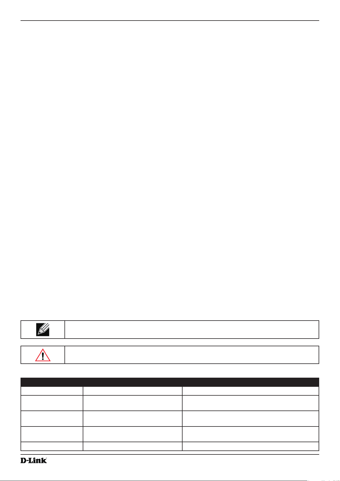
Note: A note provides more information about a feature or technology and cross-references to
related topics.
Caution! A caution provides information about critical aspects of AP conguration, combinations of
settings, events, or procedures that can adversely affect network connectivity, security, and so on.
The following table describes the typographical conventions used in this guide.
Symbol Example Description
Bold Click Apply to save your settings. Menu titles, page names, and button names.
Blue Text See “Document Conventions” on
page 9
Courier Font WLAN-AP# show network
Courier Font
Italics
Square Brackets [ ] [Value] Indicates an optional xed parameter.
April 2015
Value
Hyperlink text.
Screen text, le names, commands, user-typed
command-line entries.
Command parameter, which might be a variable or
xed value.
Unied Access Point Administrator’s Guide
Page 9
Unied Access Point Administrator’s Guide
Symbol Example Description
Curly Braces {} {Choice1 | Choice2} Indicates that you must select a parameter from the
list of choices.
Vertical Bars | Choice1 | Choice2 Separates the mutually exclusive choices.
Braces within square
brackets [{}]
[{Choice1 | Choice2}] Indicate a choice within an optional element.
Table 1 - Typographical Conventions
Section 1 - About This Document
Online Help, Supported Browsers, and Limitations
Online help for the UAP Administration Web pages provides information about all elds and features available from
the user interface (UI). The information in the online help is a subset of the information available in the Unied Access
Point Administrator’s Guide.
Online help information corresponds to each page on the UAP Administration UI.
For information about the settings on the current page, click the Help link on the upper right side of a page.
The following gure shows an example of the online help available from the links on the user interface.
April 2015
Figure 1 - Administrator UI Online Help
Unied Access Point Administrator’s Guide
Page 10

Unied Access Point Administrator’s Guide
Section 2 - Getting Started
Section 2 - Getting Started
The D-Link DWL-x600AP unied access point (UAP) provides continuous, high-speed access between wireless
devices and Ethernet devices. It is an advanced, standards-based solution for wireless networking in businesses of
any size. The UAP enables wireless local area network (WLAN) deployment while providing state-of-the-art wireless
networking features.
The UAP can operate in two modes: Standalone Mode or Managed Mode. In Standalone Mode, the UAP acts
as an individual access point in the network, and you manage it by using the Administrator Web User Interface
(UI), command-line interface (CLI), or SNMP. In Managed Mode, the UAP is part of the D-Link Unied Wired and
Wireless System, and you manage it by using the D-Link Unied Wireless Switch. If an AP is in Managed Mode, the
Administrator Web UI, Telnet, SSH, and SNMP services are disabled.
This document describes how to perform the setup, management, and maintenance of the UAP in Standalone Mode.
For information about conguring the AP in Managed Mode by using the D-Link Unied Wireless Switch, see the User
Manual for the switch.
Before you power on a new UAP, review the following sections to check required hardware and software components,
client congurations, and compatibility issues. Make sure you have everything you need for a successful launch and
test of your new or extended wireless network.
The DWL-6600AP and DWL-8600AP are dual-radio access points and support the IEEE 802.11a, 802.11b, 802.11g,
and 802.11n modes. The DWL-2600AP and DWL-3600AP are single-radio access points and support the IEEE
802.11b, IEEE 802.11g, and 802.11n (2.4 GHz) modes.
This section contains the following topics:
•) “Administrator’s Computer Requirements” on page 11
•) “Wireless Client Requirements” on page 12
•) “Dynamic and Static IP Addressing on the AP” on page 13
•) “Installing the UAP” on page 13
•) “Basic Settings” on page 16
•) “Using the CLI to View the IP Address” on page 17
•) “Conguring the Ethernet Settings” on page 18
•) “Conguring IEEE 802.1X Authentication” on page 19
•) “Verifying the Installation” on page 20
•) “Conguring Security on the Wireless Access Point” on page 21
To manage the UAP by using the Web interface or by using the CLI through Telnet or SSH, the AP needs an IP
address. If you use VLANs or IEEE 802.1X Authentication (port security) on your network, you might need to congure
additional settings on the AP before it can connect to the network.
Note: The WLAN AP is not designed to function as a gateway to the Internet. To connect your
WLAN to other LANs or the Internet, you need a gateway device.
Administrator’s Computer Requirements
The following table describes the minimum requirements for the administrator’s computer for conguration and
administration of the UAP through a Web-based user interface (UI).
Required Software or Component Description
Serial or Ethernet Connection to the
Access Point
April 2015
The computer used to congure the rst access point must be connected
to the access point by a serial cable or an Ethernet cable.
Unied Access Point Administrator’s Guide
Page 11

Unied Access Point Administrator’s Guide
Section 2 - Getting Started
Required Software or Component Description
Wireless Connection to the Network After initial conguration and launch of the rst access point on your
new wireless network, you can make subsequent conguration changes
through the Administration Web pages using a wireless connection to the
internal network.
For wireless connection to the access point, your administration device will
need Wi-Fi capability similar to that of any wireless client:
•) Portable or built-in Wi-Fi client adapter that supports one or more of
the IEEE 802.11 modes in which you plan to run the access point.
•) Wireless client software congured to associate with the UAP.
Web Browser and Operating System Conguration and administration of the UAP is provided through a Web-
based user interface hosted on the access point.
We recommend using one of the following supported Web browsers to
access the access point Administration Web pages:
•) Microsoft
®
Internet Explorer® version 7.x or 8.x (with up-to-date patch
level for either major version)
•) Mozilla® Firefox version 3.5 or later
•) Safari 5 and later versions
The administration Web browser must have JavaScript™ enabled to
support the interactive features of the administration interface.
Security Settings Ensure that security is disabled on the wireless client used to initially
congure the access point.
Table 2 - Requirements for the Administrator’s Computer
Wireless Client Requirements
The UAP provides wireless access to any client with a properly congured Wi-Fi client adapter for the 802.11 mode
in which the access point is running. The UAP supports multiple client operating systems. Clients can be laptop or
desktop computers, personal digital assistants (PDAs), or any other hand-held, portable or stationary device equipped
with a Wi-Fi adapter and supporting drivers.
To connect to the access point, wireless clients need the software and hardware described in the following table.
Required Component Description
Wi-Fi Client Adapter Portable or built-in Wi-Fi client adapter that supports one or more of the
IEEE 802.11 modes in which you plan to run the access point.
Wireless Client Software Client software, such as Microsoft Windows Supplicant, congured to
associate with the UAP.
Client Security Settings Security should be disabled on the client used to do initial conguration of
the access point.
If the Security mode on the access point is set to anything other than plain
text, wireless clients will need to set a prole to the authentication mode
used by the access point and provide a valid username and password,
certicate, or similar user identity proof. Security modes are Static WEP,
IEEE 802.1X, WPA with RADIUS server, and WPA-PSK.
April 2015
For information about conguring security on the access point, see “Virtual
Access Point Settings” on page 47.
Table 3 - Requirements for Wireless Clients
Unied Access Point Administrator’s Guide
Page 12
Unied Access Point Administrator’s Guide
Section 2 - Getting Started
Dynamic and Static IP Addressing on the AP
When you power on the access point, the built-in DHCP client searches for a DHCP server on the network in order
to obtain an IP Address and other network information. If the AP does not nd a DHCP server on the network, the AP
continues to use its default Static IP Address (10.90.90.91) until you re-assign it a new static IP address (and specify a
static IP addressing policy) or until the AP successfully receives network information from a DHCP server.
To change the connection type and assign a static IP address by using the CLI, see “Conguring the Ethernet
Settings” on page 18 or, by using the Web UI, see “Ethernet Settings” on page 35.
Caution! If you do not have a DHCP server on your internal network, and do not plan to use one,
the rst thing you must do after powering on the access point is change the connection type from
DHCP to static IP. You can either assign a new static IP address to the AP or continue using the
default address. We recommend assigning a new static IP address so that if you bring up another
WLAN AP on the same network, the IP address for each AP will be unique.
Recovering an IP Address
If you experience trouble communicating with the access point, you can recover a static IP address by resetting the AP
conguration to the factory defaults (see “Resetting the Factory Default Conguration” on page 81), or you can get
a dynamically assigned address by connecting the AP to a network that has a DHCP server.
Discovering a Dynamically Assigned IP Address
If you have access to the DHCP server on your network and know the MAC address of your AP, you can view the new
IP address associated with the MAC address of the AP.
If you do not have access to the DHCP server that assigned the IP address to the AP or do not know the MAC address
of the AP, you might need to use the CLI to nd out what the new IP address is. For information about how to discover
a dynamically assigned IP address, see “Using the CLI to View the IP Address” on page 17.
Installing the UAP
To access the Administration Web UI, you enter the IP address of the AP into a Web browser. You can use the default
IP address of the AP (10.90.90.91) to log on to the AP and assign a static IP address, or you can use a DHCP server
on you network to assign network information to the AP. The DHCP client on the AP is enabled by default.
To install the UAP, use the following steps:
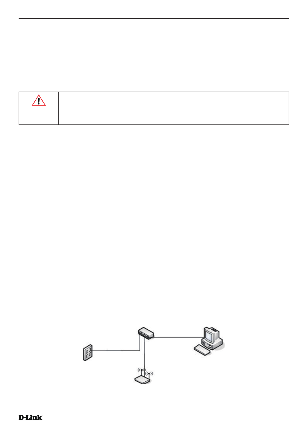
1.) Connect the AP to an administrative PC by using a LAN connection or a direct-cable connection.
•) To use a LAN connection, connect one end of an Ethernet cable to the network port on the access point and
the other end to the same hub where your PC is connected, as shown in the following gure.
The hub or switch you use must permit broadcast signals from the access point to reach all other devices on
the network.
April 2015
Unied Access Point Administrator’s Guide
Page 13
Unied Access Point Administrator’s Guide
Section 2 - Getting Started
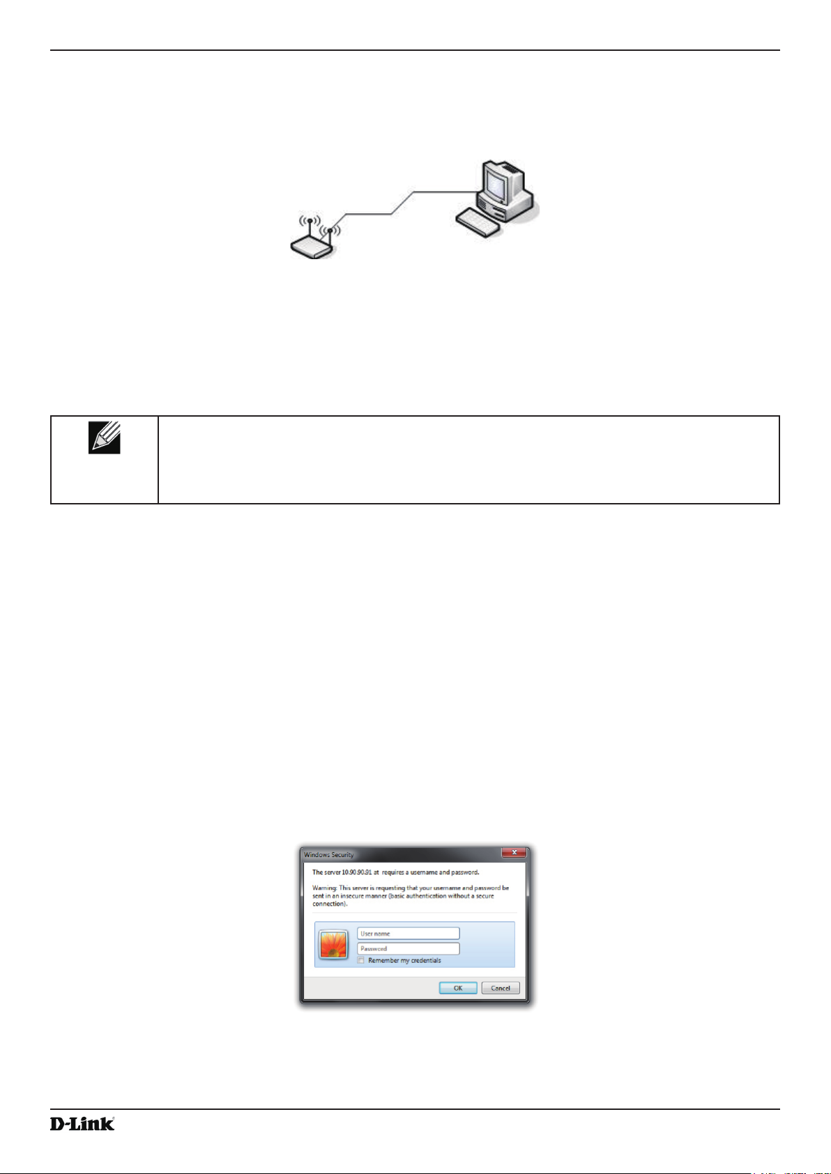
•) To use a direct-cable connection, connect one end of an Ethernet straight-through or crossover cable to the
network port on the access point and the other end of the cable to the Ethernet port on the PC, as shown in
the following gure. You can also use a serial cable to connect the serial port on the AP to a serial port on the
administrative computer.
For initial conguration with a direct Ethernet connection and no DHCP server, be sure to set your PC to a
static IP address in the same subnet as the default IP address on the access point. (The default IP address for
the access point is 10.90.90.91.)
If you use this method, you will need to recongure the cabling for subsequent startup and deployment of the
access point so that the access point is no longer connected directly to the PC but instead is connected to the
LAN (either by using a hub or directly).
Note: It is possible to detect access points on the network with a wireless connection. However,
we strongly advise against using this method. In most environments you may have no way
of knowing whether you are actually connecting to the intended AP. Also, many of the initial
conguration changes required will cause you to lose connectivity with the AP over a wireless
connection.
2.) Connect the power adapter to the power port on the back of the access point, and then plug the other end of the
power cord into a power outlet.
3.) Use your Web browser to log on to the UAP Administration Web pages.
•) If the AP did not acquire an IP address from a DHCP server on your network, enter 10.90.90.91 in the address
eld of your browser, which is the default IP address of the AP.
•) If you used a DHCP server on your network to automatically congure network information for the AP, enter the
new IP address of the AP into the Web browser.
•) If you used a DHCP server and you do not know the new IP address of the AP, use the following procedures to
obtain the information:
•) Connect a serial cable from the administrative computer to the AP and use a terminal emulation program to
access the command-line interface (CLI).
•) At the login prompt, enter admin for the user name and admin for the password. At the command prompt,
enter get management.
•) The command output displays the IP address of the AP. Enter this address in the address eld of your browser.
For a more detailed explanation about how to log on to the CLI by using the console port, see “Using the CLI
to View the IP Address” on page 24.
4.) When prompted, enter admin for the user name and admin for the password, then click Logon.
When you rst log in, the Basic Settings page for UAP administration is displayed, as the following gure
shows.
April 2015
Figure 2 - Web UI Login Prompt
Unied Access Point Administrator’s Guide
Page 14
Unied Access Point Administrator’s Guide
Section 2 - Getting Started
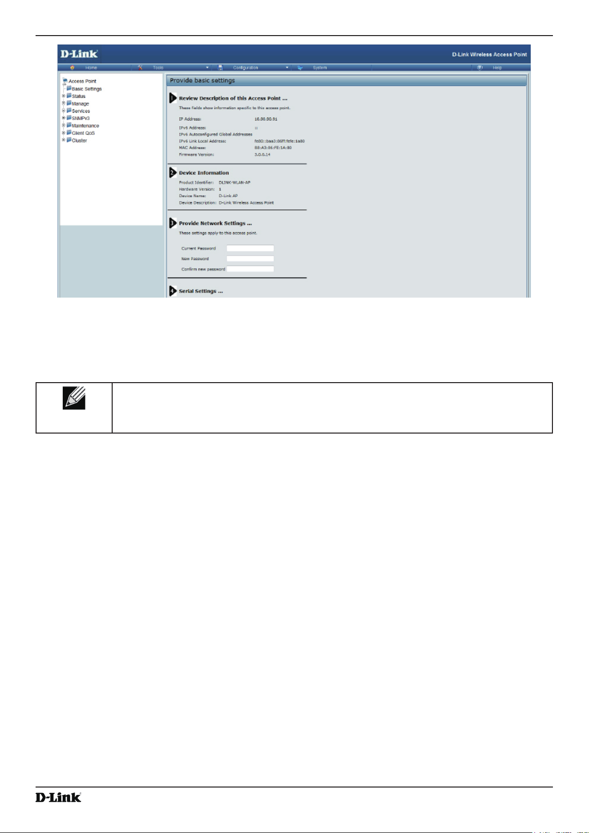
Figure 3 - Provide Basic Settings
5.) Verify the settings on the Basic Settings page.
•) Review access point description and provide a new administrator password for the access point if you do not
want to use the default password, which is admin.
•) Click the Apply button to activate the wireless network with these new settings.
Note: The changes you make are not saved or applied until you click Apply. Changing some
access point settings might cause the AP to stop and restart system processes. If this happens,
wireless clients will temporarily lose connectivity. We recommend that you change access point
settings when WLAN trafc is low.
For information about the elds and conguration options on the Basic Settings page, see “Basic Settings” on
page 16.
6.) If you do not have a DHCP server on the management network and do not plan to use one, you must change
the Connection Type from DHCP to Static IP.
You can either assign a new Static IP address to the AP or continue using the default address. We recommend
assigning a new Static IP address so that if you bring up another UAP on the same network, the IP address
for each AP will be unique. To change the connection type and assign a static IP address, see “Conguring the
Ethernet Settings” on page 18 (CLI) or “Ethernet Settings” on page 35 (Web).
7.) If your network uses VLANs, you might need to congure the management VLAN ID or untagged VLAN ID on
the UAP in order for it to work with your network.
For information about how to congure VLAN information, see “Conguring the Ethernet Settings” on page 18
(CLI) or “Ethernet Settings” on page 35 (Web).
8.) If your network uses IEEE 802.1X port security for network access control, you must congure the 802.1X
supplicant information on the AP.
For information about how to congure the 802.1X user name and password, see “Conguring IEEE 802.1X
Authentication” on page 19.
Unied Access Point Administrator’s Guide
April 2015
Page 15

Unied Access Point Administrator’s Guide
Section 2 - Getting Started
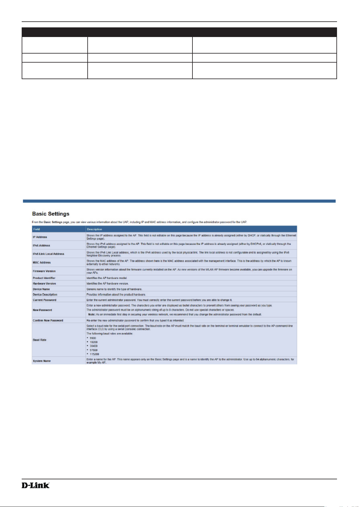
Basic Settings
From the Basic Settings page, you can view various information about the UAP, including IP and MAC address
information, and congure the administrator password for the UAP. The following table describes the elds and
conguration options on the Basic Settings page.
Field Description
IP Address Shows the IP address assigned to the AP. This eld is not editable on this page because
the IP address is already assigned (either by DHCP, or statically through the Ethernet
Settings page).
IPv6 Address Shows the IPv6 address assigned to the AP. This eld is not editable on this page because
the IP address is already assigned (either by DHCPv6, or statically through the Ethernet
Settings page).
IPv6 Address Status Shows the operational status of the static IPv6 address assigned to the management
interface of the AP. The possible values are Operational and Tentative.
IPv6 Autocongured
Global Addresses
IPv6 Link Local
Address
MAC Address Shows the MAC address of the AP. The address shown here is the MAC address
Firmware Version Shows version information about the rmware currently installed on the AP. As new
Product Identier Identies the AP hardware model.
Hardware Version Identies the AP hardware version.
Serial Number Shows the AP serial number.
Device Name Generic name to identify the type of hardware.
Device Description Provides information about the product hardware.
Current Password Enter the current administrator password. You must correctly enter the current password
New Password Enter a new administrator password. The characters you enter are displayed as bullet
Shows each automatically-congured global IPv6 address for the management interface of
the AP.
Shows the IPv6 Link Local address, which is the IPv6 address used by the local physical
link. The link local address is not congurable and is assigned by using the IPv6 Neighbor
Discovery process.
associated with the management interface. This is the address by which the AP is known
externally to other networks.
versions of the WLAN AP rmware become available, you can upgrade the rmware on
your APs.
before you are able to change it.
characters to prevent others from seeing your password as you type.
The administrator password must be an alphanumeric string of up to 8 characters. Do not
use special characters or spaces.
Note: As an immediate rst step in securing your wireless network, we recommend that
you change the administrator password from the default.
Conrm New
Password
Baud Rate Select a baud rate for the serial port connection. The baud rate on the AP must match the
System Name Enter a name for the AP. This name appears only on the Basic Settings page and is a
April 2015
Re-enter the new administrator password to conrm that you typed it as intended.
baud rate on the terminal or terminal emulator to connect to the AP command-line interface
(CLI) by using a serial (console) connection.
The following baud rates are available:
•) 9600
•) 19200
•) 38400
•) 57600
•) 115200
name to identify the AP to the administrator. Use up to 64 alphanumeric characters, for
example My AP.
Unied Access Point Administrator’s Guide
Page 16

Unied Access Point Administrator’s Guide
Field Description
System Contact Enter the name, e-mail address, or phone number of the person to contact regarding
issues related to the AP.
System Location Enter the physical location of the AP, for example Conference Room A.
Table 4 - Basic Settings Page
Section 2 - Getting Started
Connecting to the AP Web Interface by Using the IPv6 Address
To connect to the AP by using the IPv6 global address or IPv6 link local address, you must enter the AP address into
your browser in a special format.
Note: The following instructions and examples work with Microsoft Internet Explorer 7 (IE7) and
might not work with other browsers.
To connect to an IPv6 global address, add square brackets around the IPv6 address. For example, if the AP
global IPv6 address is 2520::230:abff:fe00:2420, type the following address into the IE7 address eld: http://
[2520::230:abff:fe00:2420].
To connect to the iPv6 link local address, replace the colons (:) with hyphens (-), add the interface number preceded
with an “s,” then add “.ipv6-literal.net.” For example, if the AP link local address is fe80::230:abff:fe00:2420, and the
Windows interface is dened as “%6,” type the following address into the IE7 address eld: http://fe80--230-abff-fe00-
2420s6.ipv6-literal.net.
Using the CLI to View the IP Address
The DHCP client on the UAP is enabled by default. If you connect the UAP to a network with a DHCP server, the
AP automatically acquires an IP address. To manage the UAP by using the Administrator UI, you must enter the IP
address of the access point into a Web browser.
If a DHCP server on your network assigns an IP address to the UAP, and you do not know the IP address, use the
following steps to view the IP address of the UAP:
1.) Using a null-modem cable, connect a VT100/ANSI terminal or a workstation to the console (serial) port.
If you attached a PC, Apple, or UNIX workstation, start a terminal-emulation program, such as HyperTerminal or
TeraTerm.
2.) Congure the terminal-emulation program to use the following settings:
•) Baud rate: 115200 bps
•) Data bits: 8
•) Parity: none
•) Stop bit: 1
•) Flow control: none
3.) Press the return key, and a login prompt should appear.
The login name is admin. The default password is admin. After a successful login, the screen shows the
(Access Point Name)# prompt.
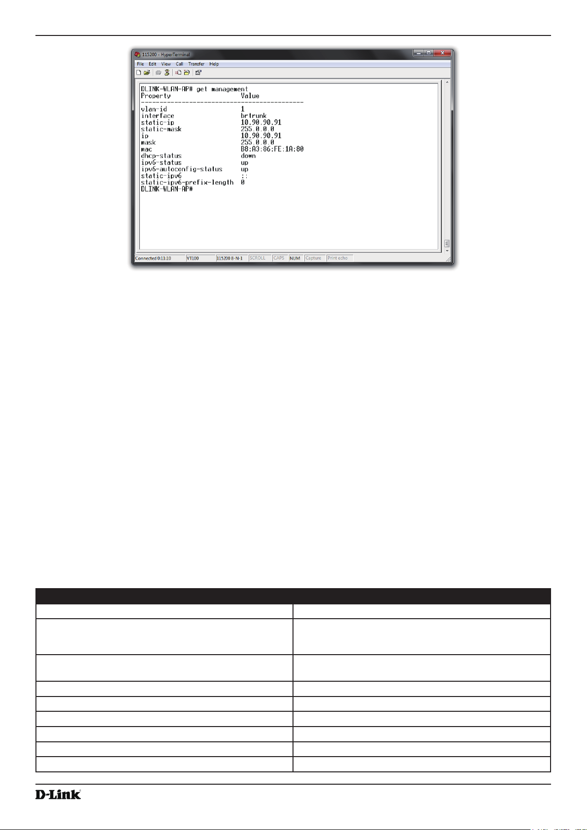
4.) At the login prompt, enter get management.
Information similar to the following prints to the screen.
April 2015
Unied Access Point Administrator’s Guide
Page 17
Unied Access Point Administrator’s Guide
Figure 4 - Command Line Interface (CLI) Connection
Section 2 - Getting Started
Conguring the Ethernet Settings
The default Ethernet settings, which include DHCP and VLAN information, might not work for all networks.
By default, the DHCP client on the UAP automatically broadcasts requests for network information. If you want to
use a static IP address, you must disable the DHCP client and manually congure the IP address and other network
information.
The management VLAN is VLAN 1 by default. This VLAN is also the default untagged VLAN. If you already have
a management VLAN congured on your network with a different VLAN ID, you must change the VLAN ID of the
management VLAN on the access point.
For information about using the Web interface to congure the Ethernet settings, see “Ethernet Settings” on page
35. You can also use the CLI to congure the Ethernet settings, which the following section describes.
Using the CLI to Congure Ethernet Settings
Use the commands shown in the following table to view and set values for the Ethernet (wired) interface. For more
information about each setting, see the description for the eld in the following table.
Action Commands
Get the DNS Name
Set the DNS Name
Get Current Settings for the Ethernet (Wired) Internal
Interface
Set the management VLAN ID
View untagged VLAN information
Enable the untagged VLAN
Disable the untagged VLAN
Set the untagged VLAN ID
View the connection type
get host id
set host id <host_name>
For example:
set host id lab-ap
get management
set management vlan-id <1-4094>
get untagged-vlan
set untagged-vlan status up
set untagged-vlan status down
set untagged-vlan vlan-id <1-4094>
get management dhcp-status
April 2015
Unied Access Point Administrator’s Guide
Page 18

Unied Access Point Administrator’s Guide
Action Commands
Use DHCP as the connection type
Use a Static IP as the connection type
Set the Static IP address
set management dhcp-status up
set management dhcp-status down
set management static-ip <ip_address>
For example:
set management static-ip 10.10.12.221
Set a Subnet Mask
set management static-mask <netmask>
For example:
set management static-mask 255.255.255.0
Set the Default Gateway
set static-ip-route gateway <ip_address>
For example:
set static-ip-route gateway 10.10.12.1
View the DNS Nameserver mode Dynamic= up
get host dns-via-dhcp
Manual=down
Set DNS Nameservers to Use Static IP Addresses
(Dynamic to Manual Mode)
set host dns-via-dhcp down
set host static-dns-1 <ip_address>
set host static-dns-2 <ip_address>
For example:
set host static-dns-1 192.168.23.45
Set DNS Nameservers to Use DHCP IP Addressing
set host dns-via-dhcp up
(Manual to Dynamic Mode)
Table 5 - CLI Commands for Ethernet Setting
Section 2 - Getting Started
In the following example, the administrator uses the CLI to set the management VLAN ID to 123 and to disable the
untagged VLAN so that all trafc is tagged with a VLAN ID.
DLINK-WLAN-AP# set management vlan-id 123
DLINK-WLAN-AP# set untagged-vlan status down
DLINK-WLAN-AP# get management
Property Value
-------------------------------------------vlan-id 123
interface brtrunk
static-ip 10.90.90.91
static-mask 255.0.0.0
ip 10.90.90.91
mask 255.0.0.0
mac 00:05:5E:80:70:00
dhcp-status down
ipv6-status up
ipv6-autocong-status up
static-ipv6 ::
static-ipv6-prex-length 0
DLINK-WLAN-AP# get untagged-vlan
Property Value
--------------vlan-id 1
status down
DLINK-WLAN-AP#
Conguring IEEE 802.1X Authentication
On networks that use IEEE 802.1X, port-based network access control, a supplicant (client) cannot gain access to
the network until the 802.1X authenticator grants access. If your network uses 802.1X, you must congure 802.1X
authentication information that the AP can supply to the authenticator.
If your network uses IEEE 802.1X see “Conguring IEEE 802.1X Authentication” on page 19 for information about
how to congure 802.1X by using the Web interface.
Unied Access Point Administrator’s Guide
April 2015
Page 19

Unied Access Point Administrator’s Guide
Section 2 - Getting Started
Using the CLI to Congure 802.1X Authentication Information
The following table shows the commands used to congure the 802.1X supplicant information using the CLI.
Action Command
View 802.1X supplicant settings
Enable 802.1X supplicant
Disable 802.1X supplicant
Set the 802.1X user name
Set the 802.1X password
Table 6 - CLI Commands for the 802.1X Supplicant
In the following example, the administrator enables the 802.1X supplicant and sets the user name to wlanAP and the
password to test1234.
DLINK-WLAN-AP# set dot1x-supplicant status up
DLINK-WLAN-AP# set dot1x-supplicant user wlanAP
DLINK-WLAN-AP# set dot1x-supplicant password test1234
DLINK-WLAN-AP# get dot1x-supplicant
Property Value
-------------------------status up
user wlanAP
eap-method md5
debug off
cert-present no
cert-exp-date Not Present
get dot1x-supplicant
set dot1x-supplicant status up
set dot1x-supplicant status down
set dot1x-supplicant user <name>
set dot1x-supplicant password <password>
DLINK-WLAN-AP#
Verifying the Installation
Make sure the access point is connected to the LAN and associate some wireless clients with the network. Once you
have tested the basics of your wireless network, you can enable more security and ne-tune the AP by modifying
advanced conguration features.
1.) Connect the access point to the LAN.
•) If you congured the access point and administrator PC by connecting both into a network hub, then your
access point is already connected to the LAN. The next step is to test some wireless clients.
•) If you congured the access point by using a direct cable connection from your computer to the access point,
do the following procedures:
•) Disconnect the cable from the computer and the access point.
•) Connect an Ethernet cable from the access point to the LAN.
•) Connect your computer to the LAN by using an Ethernet cable or a wireless card.
2.) Test LAN connectivity with wireless clients.
Test the UAP by trying to detect it and associate with it from some wireless client devices. For information about
requirements for these clients, see “Wireless Client Requirements” on page 12.
3.) Secure and congure the access point by using advanced features.
Once the wireless network is up and you can connect to the AP with some wireless clients, you can add in layers
of security, create multiple virtual access points (VAPs), and congure performance settings.
Note: The WLAN AP is not designed for multiple, simultaneous conguration changes. If more
than one administrator is logged onto the Administration Web pages and making changes to the
conguration, there is no guarantee that all conguration changes specied by multiple users will
be applied.
By default, no security is in place on the access point, so any wireless client can associate with it and access
your LAN. An important next step is to congure security, as described in “Virtual Access Point Settings” on page
47.
Unied Access Point Administrator’s Guide
April 2015
Page 20

Unied Access Point Administrator’s Guide
Section 2 - Getting Started
Conguring Security on the Wireless Access Point
You congure secure wireless client access by conguring security for each virtual access point (VAP) that you
enable. You can congure up to 16 VAPs per radio that simulate multiple APs in one physical access point. By default,
only one VAP is enabled. For each VAP, you can congure a unique security mode to control wireless client access.
Each radio has 16 VAPs, with VAP IDs from 0-15. By default, only VAP 0 on each radio is enabled. VAP0 has the
following default settings:
•) VLAN ID: 1
•) Broadcast SSID: Enabled
•) SSID: dlink1
•) Security: None
•) MAC Authentication Type: None
•) Redirect Mode: None
All other VAPs are disabled by default. The default SSID for VAPs 1–15 is ”dlinkx” where x is the VAP ID.
To prevent unauthorized access to the UAP, we recommend that you select and congure a security option other than
None for the default VAP and for each VAP that you enable.
For information about how to congure the security settings on each VAP, see “Virtual Access Point Settings” on page
47.
April 2015
Unied Access Point Administrator’s Guide
Page 21
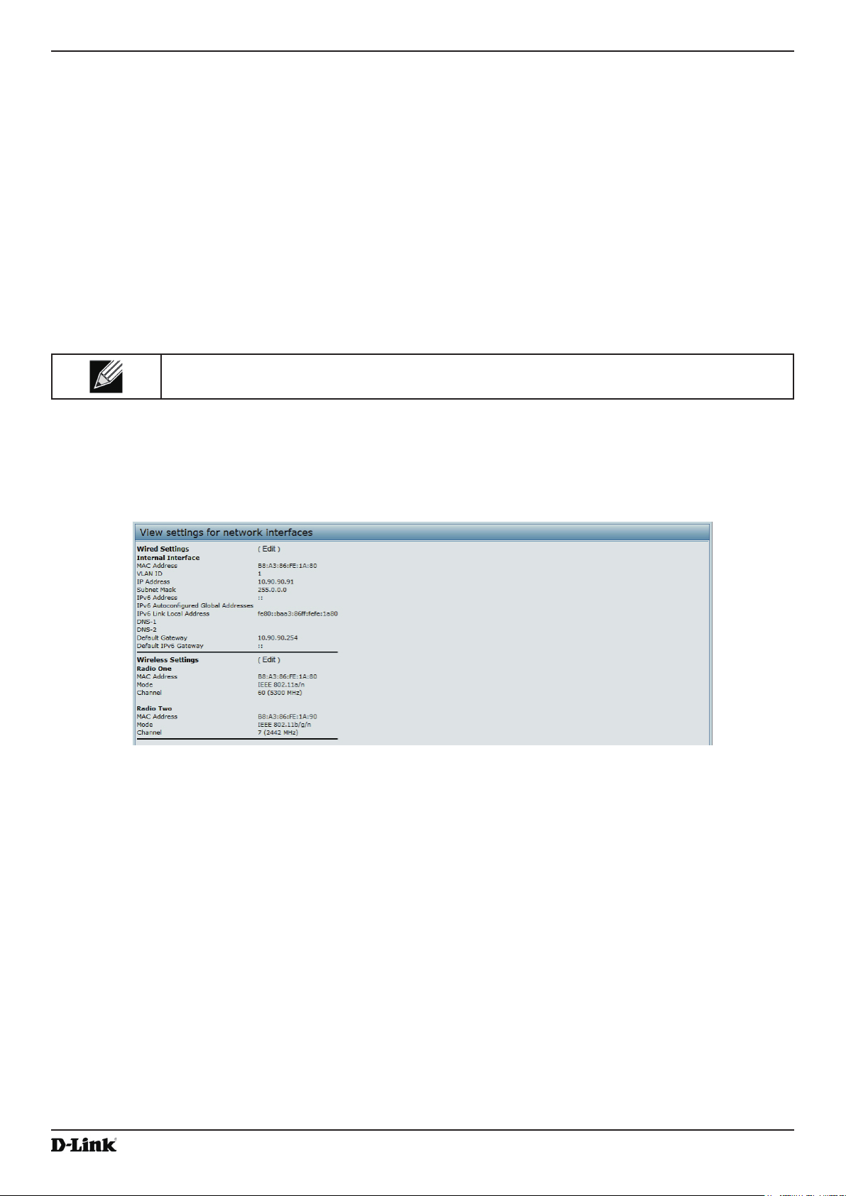
Unied Access Point Administrator’s Guide
Section 3 - Viewing Access Point Status
Section 3 - Viewing Access Point Status
This section describes the information you can view from the tabs under the Status heading on the Administration
Web UI. This section contains the following subsections:
•) “Viewing Interface Status” on page 22
•) “Viewing Events” on page 23
•) “Viewing Transmit and Receive Statistics” on page 25
•) “Viewing Associated Wireless Client Information” on page 26
•) “Viewing TSPEC Client Associations” on page 26
•) “Viewing Rogue AP Detection” on page 28
•) “Viewing Managed AP DHCP Information” on page 31
•) “Viewing TSPEC Status and Statistics Information” on page 31
•) “Viewing TSPEC AP Statistics Information” on page 32
•) “Viewing Radio Statistics Information” on page 33
•) “Viewing Email Alert Operational Status” on page 34
Note: The web-based UI images show the DWL-8600AP administration pages. Pages for the
DWL-2600AP or DWL-3600AP will display information for one radio only.
Viewing Interface Status
To monitor Ethernet LAN (wired) and wireless LAN (WLAN) settings, click the Interfaces tab.
Figure 5 - Viewing Interface Status
This page displays the current settings of the UAP. It displays the Wired Settings and the Wireless Settings.
Wired Settings (Internal Interface)
The Internal interface includes the Ethernet MAC Address, Management VLAN ID, IP Address (IPv4 and IPv6),
Subnet Mask, and DNS information. To change any of these settings, click the Edit link. After you click Edit, you are
redirected to the Ethernet Settings page.
For information about conguring these settings, see “Conguring the Ethernet Settings” on page 18.
Wireless Settings
The Radio Interface includes the AeroScout™ Engine Communication status, Radio Mode and Channel. The
Wireless Settings section also shows the MAC address (read-only) associated with each radio interface.
To change the Radio Mode or Channel settings, click the Edit link. After you click Edit, you are redirected to the
Unied Access Point Administrator’s Guide
April 2015
Page 22
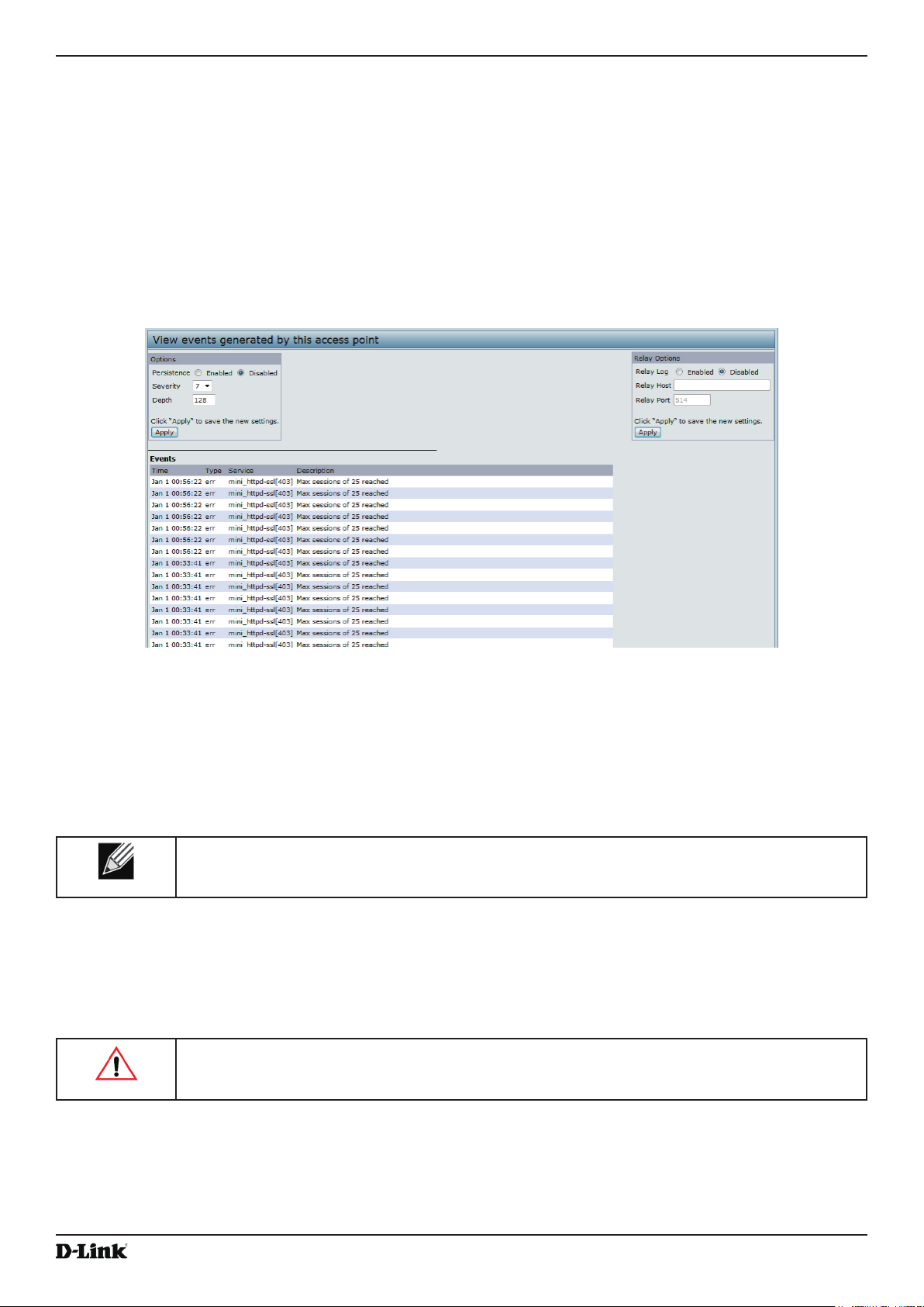
Unied Access Point Administrator’s Guide
Modify Wireless Settings page.
For information about conguring these settings, see “Wireless Settings” on page 37 and “Modifying Radio Settings”
on page 40.
Section 3 - Viewing Access Point Status
Viewing Events
The Events page shows real-time system events on the AP such as wireless clients associating with the AP and being
authenticated.
To view system events, click the Events tab.
Figure 6 - Viewing Events
From the Events page, you can perform the following tasks:
•) View the most recent, high-level events generated by this AP.
•) Enable and congure Persistent logging to write system event logs to non-volatile memory so that the events
are not erased when the system reboots.
•) Set a Severity Level to determine what category of log messages are displayed.
•) Set Depth to determine how many log messages are displayed in the Event log.
•) Enable a remote log relay host to capture all system events and errors in a Kernel Log.
Note: The AP acquires its date and time information using the network time protocol (NTP). This
data is reported in UTC format (also known as Greenwich Mean Time). You need to convert the
reported time to your local time.
Conguring Persistent Logging Options
If the system unexpectedly reboots, log messages can be useful to diagnose the cause. However, log messages are
erased when the system reboots unless you enable persistent logging.
Caution! Enabling persistent logging can wear out the ash (non-volatile) memory and degrade
network performance. You should only enable persistent logging to debug a problem. Make sure
you disable persistent logging after you nish debugging the problem.
To congure persistent logging on the Events page, set the persistence, severity, and depth options as described in
the following table, and then click Apply.
Unied Access Point Administrator’s Guide
April 2015
Page 23
Unied Access Point Administrator’s Guide
Field Description
Persistence Choose Enabled to save system logs to non-volatile memory so that the logs are not erased
when the AP reboots. Choose Disabled to save system logs to volatile memory. Logs in
volatile memory are deleted when the system reboots.
Severity Specify the severity level of the log messages to write to non-volatile memory. For example,
if you specify 2, critical, alert, and emergency logs are written to non-volatile memory. Error
messages with a severity level of 3 – 7 are written to volatile memory.
•) 0 — emergency
•) 1 — alert
•) 2 — critical
•) 3 — error
•) 4 — warning
•) 5 — notice
•) 6 — info
•) 7 — debug
Depth You can store up to 128 messages in non-volatile memory. Once the number you congure
in this eld is reached, the oldest log event is overwritten by the new log event.
Table 7 - Logging Options
Note: To apply your changes, click Apply. Changing some settings might cause the AP to stop
and restart system processes. If this happens, wireless clients will temporarily lose connectivity.
We recommend that you change AP settings when WLAN trafc is low.
Section 3 - Viewing Access Point Status
Conguring the Log Relay Host for Kernel Messages
The Kernel Log is a comprehensive list of system events (shown in the System Log) and kernel messages such as
error conditions, like dropping frames.
You cannot view kernel log messages directly from the Administration Web UI for an AP. You must rst set up a remote
server running a syslog process and acting as a syslog log relay host on your network. Then, you can congure the
UAP to send syslog messages to the remote server.
Remote log server collection for AP syslog messages provides the following features:
•) Allows aggregation of syslog messages from multiple APs
•) Stores a longer history of messages than kept on a single AP
•) Triggers scripted management operations and alerts
To use Kernel Log relaying, you must congure a remote server to receive the syslog messages. The procedure to
congure a remote log host depends on the type of system you use as the remote host.
Note: The syslog process will default to use port 514. We recommend keeping this default port.
However; If you choose to recongure the log port, make sure that the port number you assign to
syslog is not being used by another process.
Enabling or Disabling the Log Relay Host on the Events Page
To enable and congure Log Relaying on the Events page, set the Log Relay options as described in the following
table, and then click Apply.
Field Description
Relay Log Select Enabled to allow the UAP to send log messages to a remote host. Select Disabled
to keep all log messages on the local system.
Relay Host Specify the IP Address or DNS name of the remote log server.
Relay Port Specify the Port number for the syslog process on the Relay Host.
The default port is 514.
Table 8 - Log Relay Host
Unied Access Point Administrator’s Guide
April 2015
Page 24
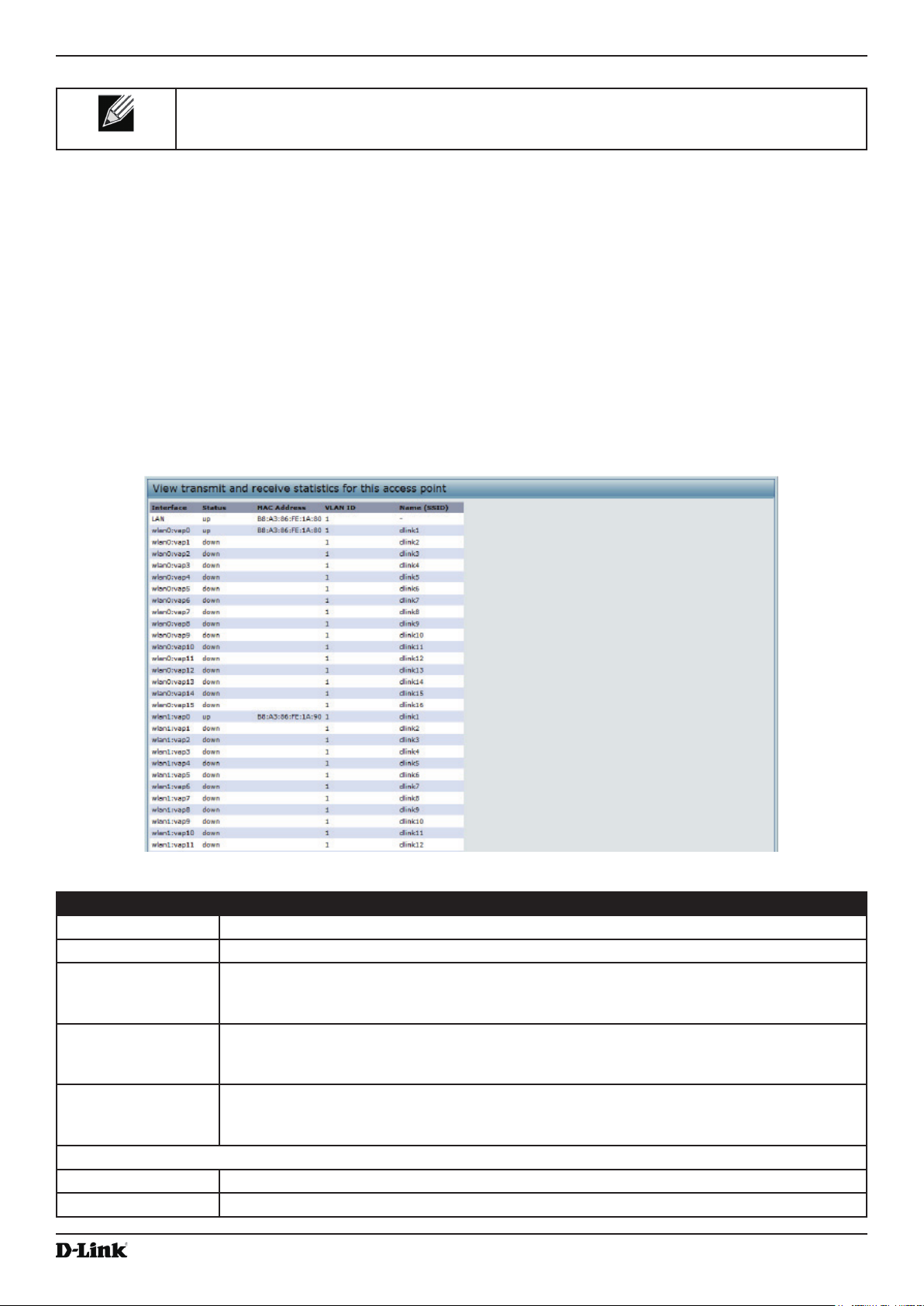
Unied Access Point Administrator’s Guide
Note: To apply your changes, click Apply. Changing some settings might cause the AP to stop
and restart system processes. If this happens, wireless clients will temporarily lose connectivity.
We recommend that you change AP settings when WLAN trafc is low.
If you enabled the Log Relay Host, clicking Apply will activate remote logging. The AP will send its kernel messages
real-time for display to the remote log server monitor, a specied kernel log le, or other storage, depending on how
you congured the Log Relay Host.
If you disabled the Log Relay Host, clicking Apply will disable remote logging.
Section 3 - Viewing Access Point Status
Viewing Transmit and Receive Statistics
The Transmit/Receive page provides some basic information about the current AP and a real-time display of the
transmit and receive statistics for the Ethernet interface on the AP and for the VAPs on all supported radio interfaces.
All transmit and receive statistics shown are totals since the AP was last started. If you reboot the AP, these gures
indicate transmit and receive totals since the reboot.
To view transmit and receive statistics for the AP, click the Transmit/Receive page.
Figure 7 - Viewing Trafc Statistics
Field Description
Interface The name of the Ethernet or VAP interface.
Status Shows whether the interface is up or down.
MAC Address MAC address for the specied interface. The UAP has a unique MAC address for each
interface. Each radio has a different MAC address for each interface on each of its two
radios.
VLAN ID Virtual LAN (VLAN) ID.
You can use VLANs to establish multiple internal and guest networks on the same AP.
The VLAN ID is set on the VAP page. (See “Conguring Load Balancing” on page 60)
Name (SSID) Wireless network name. Also known as the SSID, this alphanumeric key uniquely identies a
wireless local area network.
The SSID is set on the VAP page. (See “Conguring Load Balancing” on page 60)
Transmit and Receive Information
Total Packets Indicates total packets sent (in Transmit table) or received (in Received table) by this AP.
Total Bytes Indicates total bytes sent (in Transmit table) or received (in Received table) by this AP.
Unied Access Point Administrator’s Guide
April 2015
Page 25
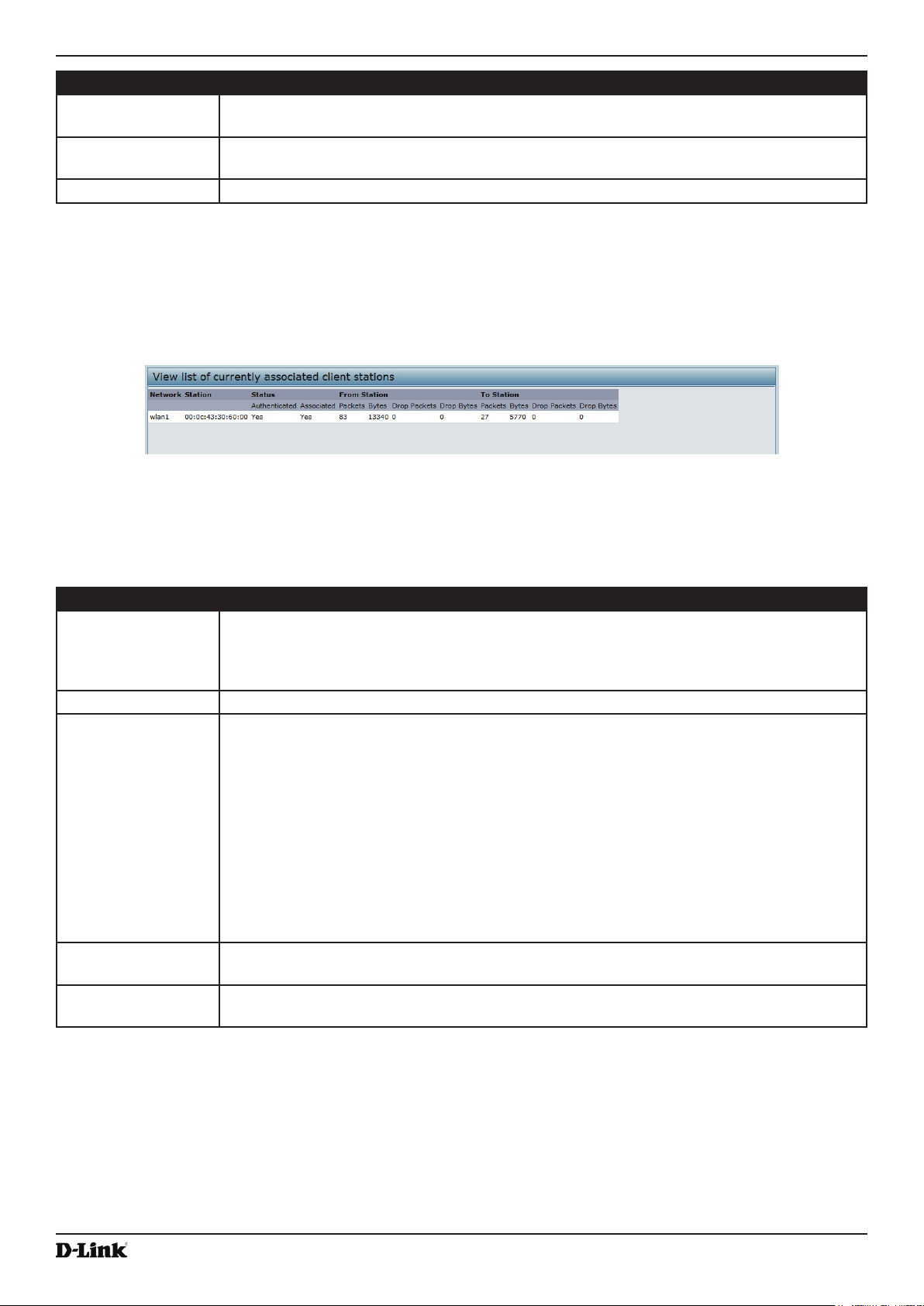
Unied Access Point Administrator’s Guide
Field Description
Total Drop Packets Indicates total number of packets sent (in Transmit table) or received (in Received table) by
this AP that were dropped.
Total Drop Bytes Indicates total number of bytes sent (in Transmit table) or received (in Received table) by
this AP that were dropped.
Errors Indicates total errors related to sending and receiving data on this AP.
Table 9 - Transmit/Receive
Section 3 - Viewing Access Point Status
Viewing Associated Wireless Client Information
To view the client stations associated with a particular access point, click the Client Associations tab.
Figure 8 - Viewing Client Association Information
The associated stations are displayed along with information about packet trafc transmitted and received for each
station.
The following describes the elds on the Client Associations page.
Field Description
Network Shows which VAP the client is associated with. For example, an entry of wlan0vap2 means
the client is associated with Radio 1, VAP 2.
An entry of wlan0 means the client is associated with VAP 0 on Radio 1. An entry of wlan1
means the client is associated with VAP 0 on Radio 2.
Station Shows the MAC address of the associated wireless client.
Status The Authenticated and Associated Status shows the underlying IEEE 802.11 authentication
and association status, which is present no matter which type of security the client uses to
connect to the AP. This status does not show IEEE 802.1X authentication or association
status.
Some points to keep in mind with regard to this eld are:
•) If the AP security mode is None or Static WEP, the authentication and association
status of clients showing on the Client Associations page will be in line with what is
expected; that is, if a client shows as authenticated to the AP, it will be able to transmit
and receive data. (This is because Static WEP uses only IEEE 802.11 authentication.)
•) If the AP uses IEEE 802.1X or WPA security, however, it is possible for a client
association to show on this page as authenticated (via the IEEE 802.11 security) but
actually not be authenticated to the AP via the second layer of security.
From Station Shows the number of packets and bytes received from the wireless client and the number of
packets and bytes that were dropped after being received.
To Station Shows the number of packets and bytes transmitted from the AP to the wireless client and
the number of packets and bytes that were dropped upon transmission.
Table 10 - Associated Clients
Viewing TSPEC Client Associations
The TSPEC Client Association Status and Statistics page provides some basic information about the client
associations status and a real-time display of the transmit and receive statistics for the TSPEC clients. All transmit and
receive statistics shown are totals since the client association started.
Unied Access Point Administrator’s Guide
April 2015
Page 26

Unied Access Point Administrator’s Guide
Section 3 - Viewing Access Point Status
A TSPEC is a trafc specication that is sent from a QoS-capable wireless client to an AP requesting a certain
amount of network access for the trafc stream (TS) it represents. A trafc stream is a collection of data packets
identied by the wireless client as belonging to a particular user priority. An example of a voice trafc stream is a Wi-Fi
CERTIFIED™ telephone handset that marks its codec-generated data packets as voice priority trafc. An example of
a video trafc stream is a video player application on a wireless laptop that prioritizes a video conference feed from a
corporate server.
To view TSPEC client association statistics, click the TSPEC Client Associations tab.
Figure 9 - Viewing TSPEC Client Associations
The following table describes the information provided on the TSPEC Client Association Status and Statistics
page.
Field Description
Status
Network Radio interface used by the client.
Station Client station MAC address.
TS Identier TSPEC Trafc Session Identier (range 0-7).
Access Category TS Access Category (voice or video).
Direction The trafc direction for this TS. Direction can be:
•) uplink
•) downlink
•) bidirectional
User Priority The User Priority (UP) for this TS. The UP is sent with each packet in the UP portion of the
IP header. Typical values are:
•) 6 or 7 for voice
•) 4 or 5 for video
The value may differ depending on other priority trafc sessions.
Medium Time The time (in 32 microsecond per second units) that the TS trafc occupies the transmission
medium.
Excess Usage
Events
The number of times the client has exceeded the medium time established for its TSPEC.
Minor, infrequent violations are ignored.
VAP The Virtual Access Point associated with this TS client.
MAC Address The Virtual Access Point MAC address.
SSID The service set identier associated with this TS client.
Statistics
Network Radio interface used by the client.
Station Client station MAC address.
TS Identier TSPEC Trafc Session Identier (range 0-7).
Access Category TS Access Category (voice or video).
Direction The trafc direction for this TS. Direction can be:
•) uplink
•) downlink
•) bidirectional
April 2015
Unied Access Point Administrator’s Guide
Page 27
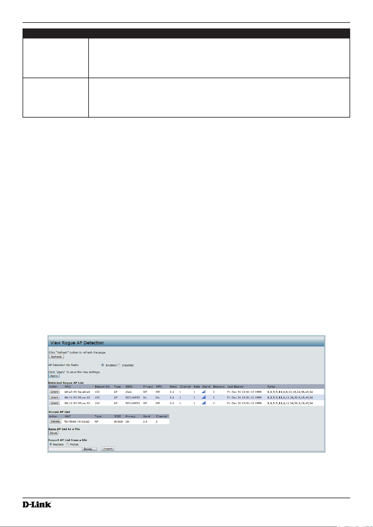
Unied Access Point Administrator’s Guide
Field Description
From Station Shows the number of packets and bytes received from the wireless client and the number
of packets and bytes that were dropped after being received. Also shows the number of
packets:
•) in excess of an admitted TSPEC.
•) for which no TSPEC has been established when admission is required by the AP.
To Station Shows the number of packets and bytes transmitted from the AP to the wireless client and
the number of packets and bytes that were dropped upon transmission. Also shows the
number of packets:
•) in excess of an admitted TSPEC.
•) for which no TSPEC has been established when admission is required by the AP.
Table 11 - TSPEC Client Associations
Section 3 - Viewing Access Point Status
Link Integrity Monitoring
The UAP provides link integrity monitoring to continually verify its connection to each associated client. To do this,
the AP sends data packets to clients every few seconds when no other trafc is passing. This allows the AP to detect
when a client goes out of range, even during periods when no normal trafc is exchanged. The client connection
drops off the list within 300 seconds if these data packets are not acknowledged, even if no disassociation message is
received.
Viewing Rogue AP Detection
The status page to view Rogue AP Detection information provides real-time statistics for all APs within range of the
AP on which you are viewing the Administration Web pages. When AP detection is enabled, the radio will periodically
switch from its operating channel to scan other channels within the same band. Click Refresh to update the screen
and display the most current information.
The Rogue AP Detection page contains the following two lists:
•) Detected Rogue AP List — Lists all APs within range of the AP that have not been acknowledged as known APs.
•) Known AP List — Lists all APs within range of the AP that have been acknowledged as known APs either by
clicking the Grant button associated with an AP in the Detected Rogue AP List or by appearing in an imported
AP list.
To view information about other access points on the wireless network, click the Rogue AP Detection tab.
Figure 10 - Viewing Rogue and Known Access Points
You must enable the AP detection on a radio in order to collect information about other APs within range.
The following table describes the information provided on neighboring access points.
Unied Access Point Administrator’s Guide
April 2015
Page 28

Unied Access Point Administrator’s Guide
Field Description
AP Detection for
Radio
Detected Rogue AP List
Action Click Grant to move the AP from the Detected Rogue AP List to the Known AP List.
MAC Shows the MAC address of the neighboring AP.
Radio The Radio eld indicates which radio detected the neighboring AP:
Beacon Int. Shows the Beacon interval being used by this AP.
Type Indicates the type of device:
SSID The Service Set Identier (SSID) for the AP.
Privacy Indicates whether there is any security on the neighboring device.
WPA Indicates whether WPA security is on or off for this AP.
Band This indicates the IEEE 802.11 mode being used on this AP. (For example, IEEE 802.11a,
Channel Shows the Channel on which the AP is currently broadcasting.
Rate Shows the rate (in megabits per second) at which this AP is currently transmitting.
Signal Indicates the strength of the radio signal emitting from this AP. If you hover the mouse
Beacons Shows the total number of beacons received from this AP since it was rst discovered.
Last Beacon Shows the date and time of the last beacon received from this AP.
Rates Shows supported and basic (advertised) rate sets for the neighboring AP. Rates are shown
To allow the AP radios to perform neighbor AP detection and collect information about
neighbor APs, click Enabled.
To disable neighbor AP detection on the radios, click Disabled.
If you change the AP detection mode, click Apply to save the new settings.
Note: The Detected Rouge AP and Known AP lists provide information. The DWL-x600AP
does not have any control over the APs on the list and cannot apply any security policies to
APs detected through the RF scan.
•) wlan0 (Radio One)
•) wlan1 (Radio Two)
Beacon frames are transmitted by an AP at regular intervals to announce the existence
of the wireless network. The default behavior is to send a beacon frame once every 100
milliseconds (or 10 per second).
The Beacon Interval is set on the Radio page.(See “Modifying Radio Settings” on page
40)
•) AP indicates the neighboring device is an AP that supports the IEEE 802.11 Wireless
Networking Framework in Infrastructure Mode.
•) Ad hoc indicates a neighboring station running in Ad hoc Mode. Stations set to ad
hoc mode communicate with each other directly, without the use of a traditional AP.
Ad-hoc mode is an IEEE 802.11 Wireless Networking Framework also referred to as
peer-to-peer mode or an Independent Basic Service Set (IBSS).
The SSID is an alphanumeric string of up to 32 characters that uniquely identies a wireless
local area network. It is also referred to as the Network Name.
The SSID is set on the VAP page. (See “Conguring Load Balancing” on page 60)
•) Off indicates that the Security mode on the neighboring device is set to None (no
security).
•) On indicates that the neighboring device has some security in place.
•) Security is congured on the AP from the VAP page.
IEEE 802.11b, IEEE 802.11g.)
The number shown indicates the mode according to the following map:
•) 2.4 indicates IEEE 802.11b, 802.11g, or 802.11n mode (or a combination of the modes)
•) 5 indicates IEEE 802.11a or 802.11n mode (or both modes)
The channel denes the portion of the radio spectrum that the radio uses for transmitting
and receiving.
The channel is set in Radio Settings. (See “Modifying Radio Settings” on page 40)
The current rate will always be one of the rates shown in Supported Rates.
pointer over the bars, a number appears and shows the strength in decibels (dB).
in megabits per second (Mbps).
All Supported Rates are listed, with Basic Rates shown in bold.
Rate sets are congured on the Radio Settings page. (See “Modifying Radio Settings” on
page 40)
Section 3 - Viewing Access Point Status
April 2015
Unied Access Point Administrator’s Guide
Page 29

Unied Access Point Administrator’s Guide
Field Description
Known AP List
Action An AP can appear in the Known AP List if it has been moved from the Detected Rogue AP
List by clicking the Grant button or if the MAC address of the AP appears in an AP list that
has been imported.
To move the AP from the Known AP List to the Detected Rogue AP List, click Delete.
Note: The Detected Rouge AP and Known AP lists provide information. The DWL-x600AP
does not have any control over the APs on the list and cannot apply any security policies to
APs detected through the RF scan.
MAC Shows the MAC address of the neighboring AP.
Type Indicates the type of device:
•) AP indicates the neighboring device is an AP that supports the IEEE 802.11 Wireless
Networking Framework in Infrastructure Mode.
•) Ad hoc indicates a neighboring station running in Ad hoc Mode. Stations set to ad
hoc mode communicate with each other directly, without the use of a traditional AP.
Ad-hoc mode is an IEEE 802.11 Wireless Networking Framework also referred to as
peer-to-peer mode or an Independent Basic Service Set (IBSS).
SSID The Service Set Identier (SSID) for the AP.
The SSID is an alphanumeric string of up to 32 characters that uniquely identies a wireless
local area network. It is also referred to as the Network Name.
The SSID is set on the VAP page. (See “Conguring Load Balancing” on page 60)
Privacy Indicates whether there is any security on the neighboring device.
•) Off indicates that the Security mode on the neighboring device is set to None (no
security).
•) On indicates that the neighboring device has some security in place.
•) Security is congured on the AP from the VAP page.
Band This indicates the IEEE 802.11 mode being used on this AP. (For example, IEEE 802.11a,
IEEE 802.11b, IEEE 802.11g.)
The number shown indicates the mode according to the following map:
•) 2.4 indicates IEEE 802.11b, 802.11g, or 802.11n mode (or a combination of the modes)
•) 5 indicates IEEE 802.11a or 802.11n mode (or both modes)
Channel Shows the Channel on which the AP is currently broadcasting.
The channel denes the portion of the radio spectrum that the radio uses for transmitting
and receiving.
The channel is set in Radio Settings. (See “Modifying Radio Settings” on page 40)
Table 12 - Rogue AP Detection
Section 3 - Viewing Access Point Status
Saving and Importing the Known AP List
To save the Known AP list to a le, click Save. The list contains the MAC addresses of all AP that have been added to
the Known AP List. By default, the lename is Rogue1.cfg. You can use a text editor or Web browser to open the le
and view its contents.
Use the Import feature to import a list of Known APs from a saved list. The list might be from another DWL-x600AP or
created from a text le. If the MAC address of an AP appears in the Known AP List, it will not be detected as a rogue.
To import an AP List from a le, use the following steps:
1.) Choose whether to replace the existing Known AP list or add the entries in the imported le to the Known AP list.
•) Select the Replace option to import the list and replace the contents of the Known AP List.
•) Select the Merge option to import the list and add the APs in the imported le to the APs currently displayed in
the Known AP List.
2.) Click Browse and choose the le to import.
•) The le you import must be a plain-text le with a .txt or .cfg extension. Entries in the le are MAC addresses
in hexadecimal format with each octet separated by colons, for example 00:11:22:33:44:55. Separate entries
with a single space. For the AP to accept the le, it must contain only MAC addresses.
3.) Click Import.
•) Once the import is complete, the screen refreshes and the MAC addresses of the APs in the imported le
Unied Access Point Administrator’s Guide
April 2015
Page 30
Loading...