


 Loading...
Hardware Installation Guide
Product Model: DXS-3600 Series
Layer 2/3 Managed 10GbE Switch Release: 1.10

DXS-3600 Series 10GbE Layer 2/3 Switch Hardware Installation Guide
Information in this document is subject to change without notice. Reproduction of this document in any manner whatsoever, without the written permission of the D-Link Corporation, is strictly forbidden.
Trademarks used in this text: D-Link and the D-Link logo are trademarks of the D-Link Corporation; Microsoft and Windows are registered trademarks of the Microsoft Corporation.
Other trademarks and trade names may be used in this document to refer to either as the entities claiming the marks and the names or their products. D-Link Corporation disclaims any proprietary interest in trademarks and trade names other than its own.
© 2012 D-Link Corporation. All rights reserved. August, 2012. P/N 651XS3632010G
FCC Warning
This equipment has been tested and found to comply with the limits for a Class A digital device, pursuant to Part 15 of the FCC Rules. These limits are designed to provide reasonable protection against harmful interference when the equipment is operating in a commercial environment. This equipment generates, uses, and can radiate radio frequency energy and, if not installed and used in accordance with this manual, may cause harmful interference to radio communications. Operation of this equipment in a residential area is likely to cause harmful interference in which case the user will be required to correct the interference at his expense.
CE Mark Warning
This is a Class A product. In a domestic environment, this product may cause radio interference in which case the user may be required to take adequate measures.
Warnung!
Dies ist ein Produkt der Klasse A. Im Wohnbereich kann dieses Produkt Funkstoerungen verursachen. In diesem Fall kann vom Benutzer verlangt werden, angemessene Massnahmen zu ergreifen.
Precaución!
Este es un producto de Clase A. En un entorno doméstico, puede causar interferencias de radio, en cuyo case, puede requerirse al usuario para que adopte las medidas adecuadas.
Attention!
Ceci est un produit de classe A. Dans un environnement domestique, ce produit pourrait causer des interférences radio, auquel cas l`utilisateur devrait prendre les mesures adéquates.
Attenzione!
Il presente prodotto appartiene alla classe A. Se utilizzato in ambiente domestico il prodotto può causare interferenze radio, nel cui caso è possibile che l`utente debba assumere provvedimenti adeguati.
VCCI Warning
A VCCI-A
i

DXS-3600 Series 10GbE Layer 2/3 Switch Hardware Installation Guide
Intended Readers
The DXS-3600 Series Hardware Installation Guide contains detailed information about the hardware specifications of a switch in this series. It also contains brief information on how to configure and manage a switch in this series. This manual is intended for advanced level users that are familiar with network management concepts and terminology. For all practical reasons the DXS-3600-32S and DXS-3600-16S will simply be referred to as the switch throughout this manual.
Typographical Conventions
Convention |
Description |
[ ] |
This convention is generally used in CLI commands. Square brackets indicate an |
|
optional entry. For example: [copy | paste] means that optionally you can type copy |
|
or you can type paste. Do not type the brackets. |
|
|
Bold Font |
This font is generally used to put emphasis on a key subject in a sentence through- |
|
out this manual. This font is also used to represent the physical CLI command used |
|
when explaining a topic. |
|
|
Boldface Typewriter Font |
This font is used to indicate CLI command examples used in this document. |
Initial capital letter |
The use of initial capital letters indicates that a referral to a specific name was made. |
|
This will be seen a lot when referring to protocols, standards, keyboard keys, and |
|
when we refer to the ‘Switch’ as a generic name for all switches with in the series. |
|
For example: Click Enter. |
|
|
Menu Name > Menu Option |
This convention indicates the referral to a menu structure found in the Web User |
|
Interface of this Switch. For example: Device > Port > Port Properties means the |
|
Port Properties menu option under the Port menu option that is located under the |
|
Device menu. |
|
|
Notes, Notices, and Cautions
NOTE: A note indicates important information that helps you make better use of your device
NOTICE: A notice indicates either potential damage to hardware or loss of data and tells you how to avoid the problem
CAUTION: A caution indicates a potential for property damage, personal injury, or death.
Safety Instructions
Please pay careful attention to the following safety guidelines to ensure your own personal safety and to help protect your system from potential damage.
ii

DXS-3600 Series 10GbE Layer 2/3 Switch Hardware Installation Guide
Safety Cautions
To greatly reduce the risk of physical injury, electrical shock, fire, and damage to equipment, observe the following precautions.
Observe and follow service markings.
•Do not attempt to service any product, except when it is explained in the system’s documentation.
•Opening or removing covers that are marked with this ( ) symbol may expose the user to electrical shock.
•Only a trained service technician should service components inside these compartments.
If any of the following conditions occur, unplug the product from the electrical outlet immediately and replace the part or contact your trained service provider:
•Damage to the power cable, extension cable, or plug.
•An object has fallen into the product.
•The product has been exposed to water.
•The product has been dropped or damaged.
•The product does not operate correctly when the operating instructions are correctly followed.
General safety cautions:
•Keep the system away from radiators and heat sources. Also, do not block cooling vents.
•Do not spill food or liquids on system components, and never operate the product in a wet environment. If the system gets wet contact your trained service provider.
•Do not push any objects into the openings of the system. Doing so can cause fire or electric shock by shorting out interior components.
•Only use this product with approved equipment.
•Allow the product to cool before removing the cover or touching internal components.
•Operate the product only from the type of external power source indicated on the electrical ratings label. If unsure of the type of power source required, consult your service provider or local power company.
•Be sure that attached devices are electrically rated to operate with the power available in your location.
•Use only approved power cable(s). If you have not been provided with a power cable for your system or for any ACpowered option intended for your system, purchase a power cable that is approved for use in your country. The power cable must be rated for the product and for the voltage and current marked on the product's electrical ratings label. The voltage and current rating of the cable should be greater than the ratings marked on the product.
•To help prevent electric shock, plug the system and peripheral power cables into properly grounded electrical outlets. These cables are equipped with three-prong plugs to help ensure proper grounding. Do not use adapter plugs or remove the grounding prong from a cable. If using an extension cable is necessary, use a 3-wire cable with properly grounded plugs.
•Observe the extension cable and power strip ratings. Make sure that the total ampere rating of all products plugged into the extension cable or power strip does not exceed 80 percent of the ampere ratings limit for the extension cable or power strip.
•To help protect the system from sudden, transient increases and decreases in electrical power, use a surge suppressor, line conditioner, or uninterruptible power supply (UPS).
•Position system cables and power cables carefully. Route cables so that they cannot be stepped on or tripped over. Be sure that nothing rests on any cables.
•Do not modify power cables or plugs. Consult a licensed electrician or your power company for site modifications. Always follow your local or national wiring rules.
When connecting or disconnecting power to and from hot-pluggable power supplies, observe the following guidelines:
•Install the power supply before connecting the power cable to the power supply.
•Unplug the power cable before removing the power supply.
•If the system has multiple sources of power, disconnect power from the system by unplugging all power cables from the power supplies.
•Move products with care and ensure that all casters and stabilizers are firmly connected to the system. Avoid sudden stops and uneven surfaces.
To help avoid damage to the system, be sure that the voltage selection switch, on the power supply, is set to match the power available at the switch’s location:
iii
DXS-3600 Series 10GbE Layer 2/3 Switch Hardware Installation Guide
•115V/60Hz is used mostly in North and South America as well as Far Eastern countries like as South Korea and Taiwan
•100V/50Hz is used mostly in Eastern Japan and 100V/60Hz in Western Japan
•230V/50Hz is used mostly in Europe, the Middle East, Africa and the Far East
General Precautions for Rack-Mountable Products
Please pay careful attention to the following precautions concerning rack stability and safety. Systems are considered to be components in a rack. Thus, a component refers to any system, as well as to various peripherals or supporting hardware.
CAUTION: Installing systems in a rack without the front and side stabilizers installed could cause the rack to tip over, potentially resulting in serious injury. After installing system/components in a rack, never pull more than one component out of the rack on its slide assemblies at one time. The weight of more than one extended component could cause the rack to tip over and may result in serious injury.
•Before working on the rack, make sure that the stabilizers are secured to the rack, extended to the floor, and that the full weight of the rack rests on the floor. Install front and side stabilizers on a single rack or front stabilizers for joined multiple racks before working on the rack.
•Always load the rack from the bottom up, and load the heaviest item in the rack first.
•Make sure that the rack is level and stable before extending a component from the rack.
•Use caution when pressing the component rail release latches and sliding a component into or out of a rack; the slide rails can pinch your fingers.
•After a component is inserted into the rack, carefully extend the rail into a locking position, and then slide the component into the rack.
•Do not overload the AC supply branch circuit that provides power to the rack. The total rack load should not exceed 80 percent of the branch circuit rating.
•Ensure that proper airflow is provided to components in the rack.
•Do not step on or stand on any component when servicing other components in a rack.
CAUTION: Never defeat the ground conductor or operate the equipment in the absence of a suitably installed ground conductor. Contact the appropriate electrical inspection authority or an electrician if uncertain that suitable grounding is available.
CAUTION: The system chassis must be positively grounded to the rack cabinet frame. Do not attempt to connect power to the system until grounding cables are connected. Completed power and safety ground wiring must be inspected by a qualified electrical inspector. An energy hazard will exist if the safety ground cable is omitted or disconnected.
Protecting Against Electrostatic Discharge
Static electricity can harm delicate components inside the system. To prevent static damage, discharge static electricity from your body before touching any of the electronic components, such as the microprocessor. This can be done by periodically touching an unpainted metal surface on the chassis.
The following steps can also be taken prevent damage from electrostatic discharge (ESD):
•When unpacking a static-sensitive component from its shipping carton, do not remove the component from the antistatic packing material until ready to install the component in the system. Just before unwrapping the antistatic packaging, be sure to discharge static electricity from your body.
•When transporting a sensitive component, first place it in an antistatic container or packaging.
•Handle all sensitive components in a static-safe area. If possible, use antistatic floor pads, workbench pads and an antistatic grounding strap.
iv

DXS-3600 Series 10GbE Layer 2/3 Switch Hardware Installation Guide
Table of Contents
Intended Readers . . . . . . . . . . . . . . . . . . . . . . . . . . . . . . . . . . . . . . . . . . . . . . . . . . . . . . . . . . . . . . . . . . . . . . . . ii Typographical Conventions. . . . . . . . . . . . . . . . . . . . . . . . . . . . . . . . . . . . . . . . . . . . . . . . . . . . . . . . . . . . . . . . . ii Notes, Notices, and Cautions . . . . . . . . . . . . . . . . . . . . . . . . . . . . . . . . . . . . . . . . . . . . . . . . . . . . . . . . . . . . . . . ii Safety Instructions. . . . . . . . . . . . . . . . . . . . . . . . . . . . . . . . . . . . . . . . . . . . . . . . . . . . . . . . . . . . . . . . . . . . . . . . ii Safety Cautions . . . . . . . . . . . . . . . . . . . . . . . . . . . . . . . . . . . . . . . . . . . . . . . . . . . . . . . . . . . . . . . . . . . . . . . . iii General Precautions for Rack-Mountable Products . . . . . . . . . . . . . . . . . . . . . . . . . . . . . . . . . . . . . . . . . . . . . . iv Protecting Against Electrostatic Discharge . . . . . . . . . . . . . . . . . . . . . . . . . . . . . . . . . . . . . . . . . . . . . . . . . . . . . iv
Introduction. . . . . . . . . . . . . . . . . . . . . . . . . . . . . . . . . . . . . . . . . . . . . . . . . . . . . . . . . . . . . . . . . . . . . . . . . . . . . . . 1
Switch Description. . . . . . . . . . . . . . . . . . . . . . . . . . . . . . . . . . . . . . . . . . . . . . . . . . . . . . . . . . . . . . . . . . . . . . . . 1 Package Contents . . . . . . . . . . . . . . . . . . . . . . . . . . . . . . . . . . . . . . . . . . . . . . . . . . . . . . . . . . . . . . . . . . . . . . . . 1 Features . . . . . . . . . . . . . . . . . . . . . . . . . . . . . . . . . . . . . . . . . . . . . . . . . . . . . . . . . . . . . . . . . . . . . . . . . . . . . . . 2 Front Panel Components . . . . . . . . . . . . . . . . . . . . . . . . . . . . . . . . . . . . . . . . . . . . . . . . . . . . . . . . . . . . . . . . . . 3 LED Indicators . . . . . . . . . . . . . . . . . . . . . . . . . . . . . . . . . . . . . . . . . . . . . . . . . . . . . . . . . . . . . . . . . . . . . . . . . 4 Rear Panel Description . . . . . . . . . . . . . . . . . . . . . . . . . . . . . . . . . . . . . . . . . . . . . . . . . . . . . . . . . . . . . . . . . . . . 5
Power Supply Module. . . . . . . . . . . . . . . . . . . . . . . . . . . . . . . . . . . . . . . . . . . . . . . . . . . . . . . . . . . . . . . . . . . . 6 Fan Module. . . . . . . . . . . . . . . . . . . . . . . . . . . . . . . . . . . . . . . . . . . . . . . . . . . . . . . . . . . . . . . . . . . . . . . . . . . . 6
Side Panel Description . . . . . . . . . . . . . . . . . . . . . . . . . . . . . . . . . . . . . . . . . . . . . . . . . . . . . . . . . . . . . . . . . . . . 6
Installation. . . . . . . . . . . . . . . . . . . . . . . . . . . . . . . . . . . . . . . . . . . . . . . . . . . . . . . . . . . . . . . . . . . . . . . . . . . . . . . . 7
Installation Guidelines . . . . . . . . . . . . . . . . . . . . . . . . . . . . . . . . . . . . . . . . . . . . . . . . . . . . . . . . . . . . . . . . . . . . . 7 Installing the Switch without a Rack . . . . . . . . . . . . . . . . . . . . . . . . . . . . . . . . . . . . . . . . . . . . . . . . . . . . . . . . . . 7 Installing the Switch into a Rack . . . . . . . . . . . . . . . . . . . . . . . . . . . . . . . . . . . . . . . . . . . . . . . . . . . . . . . . . . . . . 8 Installing Transceivers into the Transceiver Ports. . . . . . . . . . . . . . . . . . . . . . . . . . . . . . . . . . . . . . . . . . . . . . . . 9 Installing Power Modules into the Power Module Ports . . . . . . . . . . . . . . . . . . . . . . . . . . . . . . . . . . . . . . . . . . . 9
Installing an AC Power Module. . . . . . . . . . . . . . . . . . . . . . . . . . . . . . . . . . . . . . . . . . . . . . . . . . . . . . . . . . . . 10 Installing a DC Power Module . . . . . . . . . . . . . . . . . . . . . . . . . . . . . . . . . . . . . . . . . . . . . . . . . . . . . . . . . . . . 11
Installing Fan Modules into the Fan Module Ports . . . . . . . . . . . . . . . . . . . . . . . . . . . . . . . . . . . . . . . . . . . . . . 12
Switch Connections . . . . . . . . . . . . . . . . . . . . . . . . . . . . . . . . . . . . . . . . . . . . . . . . . . . . . . . . . . . . . . . . . . . . . . . 13
Switch to an End Node . . . . . . . . . . . . . . . . . . . . . . . . . . . . . . . . . . . . . . . . . . . . . . . . . . . . . . . . . . . . . . . . . . . 13 Switch to another Switch . . . . . . . . . . . . . . . . . . . . . . . . . . . . . . . . . . . . . . . . . . . . . . . . . . . . . . . . . . . . . . . . . . 13 Switch to a Server . . . . . . . . . . . . . . . . . . . . . . . . . . . . . . . . . . . . . . . . . . . . . . . . . . . . . . . . . . . . . . . . . . . . . . . 14
Switch Management . . . . . . . . . . . . . . . . . . . . . . . . . . . . . . . . . . . . . . . . . . . . . . . . . . . . . . . . . . . . . . . . . . . . . . . 15
Management Options . . . . . . . . . . . . . . . . . . . . . . . . . . . . . . . . . . . . . . . . . . . . . . . . . . . . . . . . . . . . . . . . . . . . 15 Connecting to the Console Port . . . . . . . . . . . . . . . . . . . . . . . . . . . . . . . . . . . . . . . . . . . . . . . . . . . . . . . . . . . . 15
Connecting to the Switch for the first time . . . . . . . . . . . . . . . . . . . . . . . . . . . . . . . . . . . . . . . . . . . . . . . . . . . 17 Creating a User Account. . . . . . . . . . . . . . . . . . . . . . . . . . . . . . . . . . . . . . . . . . . . . . . . . . . . . . . . . . . . . . . . . 17 Configuring the IP Address. . . . . . . . . . . . . . . . . . . . . . . . . . . . . . . . . . . . . . . . . . . . . . . . . . . . . . . . . . . . . . . 18
Connecting using SNMP . . . . . . . . . . . . . . . . . . . . . . . . . . . . . . . . . . . . . . . . . . . . . . . . . . . . . . . . . . . . . . . . . . 19
Traps. . . . . . . . . . . . . . . . . . . . . . . . . . . . . . . . . . . . . . . . . . . . . . . . . . . . . . . . . . . . . . . . . . . . . . . . . . . . . . . . 20 Management Information Base (MIB). . . . . . . . . . . . . . . . . . . . . . . . . . . . . . . . . . . . . . . . . . . . . . . . . . . . . . . 21
Connecting using the Web User Interface. . . . . . . . . . . . . . . . . . . . . . . . . . . . . . . . . . . . . . . . . . . . . . . . . . . . . 21
Logging onto the Web Manager . . . . . . . . . . . . . . . . . . . . . . . . . . . . . . . . . . . . . . . . . . . . . . . . . . . . . . . . . . . 21 Areas of the User Interface. . . . . . . . . . . . . . . . . . . . . . . . . . . . . . . . . . . . . . . . . . . . . . . . . . . . . . . . . . . . . . . 22
Appendix A - Technical Specifications . . . . . . . . . . . . . . . . . . . . . . . . . . . . . . . . . . . . . . . . . . . . . . . . . . . . . . . 23 Appendix B - Cables and Connectors . . . . . . . . . . . . . . . . . . . . . . . . . . . . . . . . . . . . . . . . . . . . . . . . . . . . . . . . 27
Ethernet Cable . . . . . . . . . . . . . . . . . . . . . . . . . . . . . . . . . . . . . . . . . . . . . . . . . . . . . . . . . . . . . . . . . . . . . . . . . 27 Console Cable. . . . . . . . . . . . . . . . . . . . . . . . . . . . . . . . . . . . . . . . . . . . . . . . . . . . . . . . . . . . . . . . . . . . . . . . . . 28
Warranty . . . . . . . . . . . . . . . . . . . . . . . . . . . . . . . . . . . . . . . . . . . . . . . . . . . . . . . . . . . . . . . . . . . . . . . . . . . . . . . . 29 Technical Support . . . . . . . . . . . . . . . . . . . . . . . . . . . . . . . . . . . . . . . . . . . . . . . . . . . . . . . . . . . . . . . . . . . . . . . . 30

DXS-3600 Series 10GbE Layer 2/3 Switch Hardware Installation Guide
Introduction
Switch Description
Package Contents
Features
Front Panel Components
Rear Panel Description
Side Panel Description
Switch Description
The DXS-3600 Series switch is a switch designed to meet the needs and requirements Data Center networks that require Top-of-Rack access switches and Enterprise/Campus aggregation switches, where low latency and high bandwidth capacity is essential. The switch is a fully managed Layer 2, for Standard Image (SI) mode, and Layer 3, for Enhanced Image (EI) mode, switch. With support for IPv4 static and dynamic routing and a plethora of advanced security and enhanced QoS features, the switch future proofs your network and provides a seamless migration path to IPv6.
The DXS-3600 Series, running in the Enhanced Image (EI) mode, is a high-performance Layer 3 switch that provides advanced Layer 3 routing features such as RIP, OSPF, BGP4, VRRP, up to 5 IP addresses per VLAN, and floating static routes. Multipath routing (which is the method of establishing multiple paths between given source-destination nodes within a network) are also features supported on the switch. These added routing features provide redundancy, load balancing, and improved network utilization for the network.
The DXS-3600 Series incorporates an advanced portfolio of security features designed to protect your network from malicious attacks. SSH encrypted management guarantee secure private configuration and monitoring when using the Graphical User Interface (GUI) and Command Line (CLI). IEEE 802.1X ports and MAC-based authentication help provide added network security by requiring all users attempting to connect to your network to provide a username and password. This username and password must then be authenticated on a RADIUS or TACACS+ server, ensuring only authorized users have access to the network. Access Control Lists (ACL) based on Layers 2/3/4, Rate Limiting, and Guest VLANs provide even more control over what and how users access the network.
The DXS-3600 Series facilitates the deployment of enterprise applications such as VoIP, streaming media, and multicast content delivery such as IP video conferencing and software deployment with enhanced enterprise features such as L2/L3/L4 QoS, IGMP and MLD snooping, 802.1w Rapid Spanning Tree, 802.1s Multiple Spanning Tree group, 802.3ad Link Aggregation, and 802.1Q VLANs.
In the DXS-3600 Series the following switches exist:
•DXS-3600-16S - which includes eight 10 Gigabit SFP+ ports and one open expansion module slot.
•DXS-3600-32S - which includes twenty-four 10 Gigabit SFP+ ports and one open expansion module slot.
Package Contents
Open the shipping carton of the Switch and carefully unpack its contents. The carton should contain the following items:
•One DXS-3600 Series switch.
•One Quick Installation Guide.
•One AC power cord.
•One AC power supply module.
•Three Fan modules.
•One RJ-45 to RS-232 console cable.
•One rack mounting kit (two brackets and screws).
•Four rubber feet with adhesive backing.
•One CD containing the Web UI Reference Guide, CLI Reference Guide, and D-View module.
1

DXS-3600 Series 10GbE Layer 2/3 Switch Hardware Installation Guide
If any item is missing or damaged, please contact your local D-Link reseller for replacement.
Features
This switch is action packed with an abundance of networking features that span inside and outside of the traditional Layer 3 framework. The list below highlights the significant protocols and features supported by this switch.
Features that can be found on this switch are:
• |
• |
• D-Link License Management System (DLMS) |
• IP Interface |
• Jumbo Frames (12 KBytes) |
• Spanning Tree Protocol (STP, RSTP, MSTP) |
• Port Mirroring |
• Link Aggregation |
• Priority-based Flow Control (PFC) |
• Layer 2 Multicast Filtering |
• IGMP Snooping (Versions 1, 2, 3) |
• IGMP and MLD Proxy |
• Secure Shell (SSH) |
• 802.1Q VLAN |
• Port-based VLAN |
• MAC-based VLAN |
• VLAN Trunking |
• Private VLAN |
• Subnet-based VLAN |
• Q-in-Q |
• VLAN Translation |
• Quality of Service (QoS) |
• Queue Handling |
• Class of Service (CoS) |
• Bandwidth Control |
• Three Color Marker |
• Congestion Control |
• Access Control List (ACL) |
• Time Based ACL |
• Traffic Segmentation |
• Port Security |
• Broadcast/Multicast/DLF Storm Control |
• BPDU Attack Protection |
• DoS Prevention |
• 802.1X Network Access Control |
• Access Authentication Control (AAA) |
• Guest VLAN |
• User Account Privilege for Management Access |
• RADIUS Accounting |
• Address Resolution Protocol (ARP) |
• Link Layer Discovery Protocol (LLDP) |
• Static Routing |
• Web-based Graphical User Interface (Web GUI) |
• Command Line Interface (CLI) |
• Traffic Monitoring |
• Telnet Server and Client |
• TFTP Client |
• FTP Client |
• Simple Network Management Protocol (SNMP) |
• System Log |
• DHCP Server and Client |
• CPU Monitoring |
• DHCP Relay |
• Trap/ Log Severity Control |
• Multiple Image and Configuration |
• Flash File System (FFS) |
• Password Recovery and Encryption |
• Simple Network Time Protocol (SNTP) |
• Debug Command |
• Traceroute and Ping |
• DNS Resolver and Relay |
• Virtual Router Redundancy Protocol (VRRP) |
• Routing Information Protocol (RIP) |
• Open Shortest Path First (OSPF) |
• Border Gateway Protocol (BGP) |
• Multicast Listener Discovery (MLD) |
• Route Preference and Distribution |
• Internet Group Management Protocol (IGMP) |
• Multicast Duplication |
• Protocol Independent Multicast (DM, SM, SSM, Sparse- |
|
Dense) |
• Distance Vector Multicast Routing Protocol (DVMRP) |
|
2
DXS-3600 Series 10GbE Layer 2/3 Switch Hardware Installation Guide
• |
• |
• Management Information Base (MIBs) for MIBII, Bridge MIB, SNMPv2 MIB, RMON MIB, RMONv2 MIB, Ether-like MIB, 802.3 MAU MIB, 802.1p MIB, IF MIB, RADIUS Authentication Client MIB, IGMPv3 MIB, RIPv2 MIB, IP Forwarding Table MIB (CIDR), IPv4 Multicast Routing MIB, PIM MIB for IPv4, RADIUS Accounting Client MIB, Ping MIB, Trace out MIB, OSPFv2 MIB, VRRP MIB, Private MIB, Entity MIB.
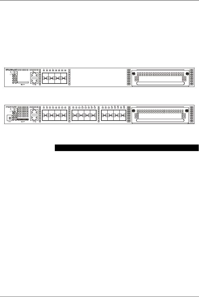
Front Panel Components
The front panel of the switch consists of LED indicators, an SD card slot, an Out-Of-Band Management port (MGMT), a Console port, SFP+ ports and an open module slot.
Figure 1-1 Front panel view of the DXS-3600-16S
|
Figure 1-2 Front panel view of the DXS-3600-32S |
Ports that can be found on the front panel of this switch are listed in the table below. |
|
|
|
Port |
Description |
|
|
SD Card Slot |
This port can be used to insert an external SD memory card. The maximum capacity |
|
SD card that can be inserted into this port is 32Gb. |
|
|
Management port (MGMT) |
This port is a 10/100/1000Mbps Ethernet port with an RJ-45 connection. This Out- |
|
Of-Band management port that can be used to configure this switch without being |
|
connected to the network. |
|
|
Console port |
This port is an RJ-45 connection port that can be used to connect to the Command |
|
Line Interface (CLI) of this switch for configuration, management and monitoring. |
|
This port uses a special console cable (included with the packing) with a DB9 |
|
interface to connect the Switch to a PC’s COM port. |
|
|
10 Gigabit ports |
This switch is equipped with SFP/SPF+/WDM ports. These ports can operate at |
|
10Gbps speeds and support a vast collection of SFP/SFP+/WDM transceivers. |
|
|
Expansion Module Slot |
This slot can be equipped with 4 kinds of additional modules. These modules are not |
|
included and should be bought seperately. |
|
• DXS-3600-EM-4XT (Four 10GBASE-T Copper ports). |
|
• DXS-3600-EM-8T (Eight 1000BASE-T Copper ports). |
|
• DXS-3600-EM-4QXS (Four 40Gbps QSFP+ transceiver slots). |
|
• DXS-3600-EM-8XS (Eight 10Gbps SFP+ transceiver slots). |
|
• DXS-3600-EM-Stack (Two 120Gbps CXP Stacking ports). This module can only |
|
be used with the DXS-3600-32S. |
|
|
For a complete list of SFP/SFP+/WDM transceivers, that are compatible with this switch, refer to the “Product Specifications” section in Appendix A.
3
DXS-3600 Series 10GbE Layer 2/3 Switch Hardware Installation Guide
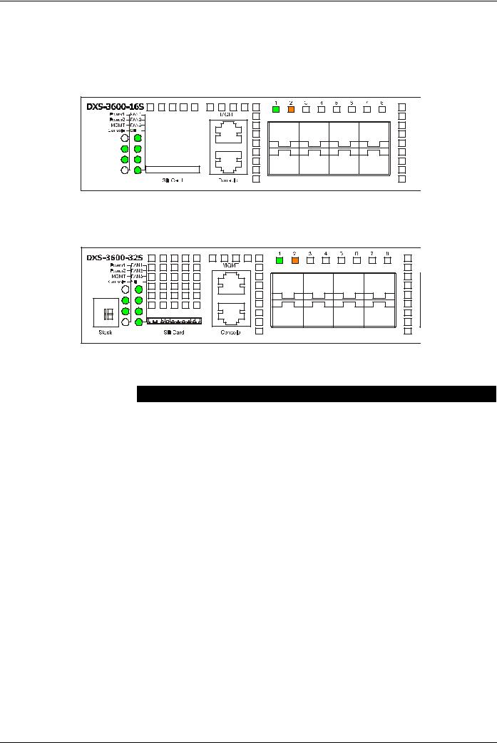
LED Indicators
Located on the front panel of the switch are LED indicators: Power1, Power2, MGMT, Console, Fan1, Fan2, Fan3, and SD. Additionally, the DXS-3600-32S also has a Seven segment stacking ID LED. For each SFP+ port there is a Link/ Act light.
Figure 1-3 LED indicators for the DXS-3600-16S |
Figure 1-4 LED indicators for the DXS-3600-32S |
LED |
Description |
|
|
Power1, Power2 |
This LED will light solid green after the Switch has been powered on successfully. |
|
This LED will light solid orange if the Switch’s power supply fails. |
|
This LED will be off when the Switch is no longer receiving power (i.e. powered off). |
|
|
Management (MGMT) |
This LED will light solid green after a link to the management port was successfully |
|
established. |
|
This LED will blink when activity on this port is taking place. |
|
This LED will be off when there is no link present or when this interface was |
|
shutdown from within the switch’s configuration. |
|
|
Console |
This LED will blink green during the Power-On Self Test (POST). |
|
This LED will light solid green when a user is logged in through the console port. |
|
This LED will be off after the POST finished successfully and no user is connected to |
|
the console port. |
|
|
Fan1, Fan2, Fan3 |
This LED will light solid green when the fan is operating normally. |
|
This LED will light solid orange when the switch is booting up or when a diagnostics |
|
test is taking place. |
|
This LED will blink orange when a fan fails. |
|
This LED will be off when the fan is not receiving power. |
|
|
SD |
This LED will light solid green if a Secure Digital (SD) card is plugged in. |
|
This LED will blink green when the Switch is reading or writing data to and from the |
|
SD card. |
|
This LED will be off when no SD card is plugged into the SD port. |
|
This LED will light solid red when an SD card failure has been detected. |
|
|
4

|
DXS-3600 Series 10GbE Layer 2/3 Switch Hardware Installation Guide |
|
|
|
|
LED |
|
Description |
|
|
|
Link/Act LEDs |
|
This LED will light solid green when there is a secure connection to a 10Gbps |
|
|
Ethernet device at any of the ports. |
|
|
This LED will light solid orange when there is a secure connection to a 1Gbps |
|
|
Ethernet device at any of the ports. |
|
|
This LED will blink green when a 10Gbps port is active, or blink orange when a |
|
|
1Gbps port is active. |
This LED will be off when there is no link or activity.
Stacking ID |
This 7-segment LED can display numbers from 1 to 12 and the following letters H, h, |
|
E, and G. The stacking ID (1 to 12) can be assigned manually by the user or |
|
automatically by the system. |
The letter ‘H’ will be displayed if this switch is the master switch in the stack.
The letter ‘h’ will be displayed if this switch is the backup master switch in the stack.
The letter ‘E’ will be displayed if there was an error in the system’s self-test.
The letter ‘G’ will be displayed when the Safeguard engine entered the exhausted mode.
Please refer to the “LED Indicators” section in the Appendix A for more LED information.
Rear Panel Description
Located on the rear panel of the switch are two power supply module slots and three fan module slots. One power supply module and three fan modules are included in the package for this switch. Any additional power supply module or fan module needs to be bought separately. This switch also supports the use of a DC power supply module.
PO WE R 1 |
|
POWER 1 |
100-240 VAC |
|
100-240 VAC |
|
50-60Hz |
|
50-60H z |
|
|
|
1.7 A MAX |
|
1.7 A MAX |
|
or |
or |
|
|
4.0 A |
|
4.0 A |
|
|
|
FA N 3 |
FA N2 |
FA N 1 |
Figure 1-5 Rear panel view of the DXS-3600-16S
POWER 1 |
|
POWER 1 |
|
|
|
100-240 VAC |
|
100-240 VAC |
50-60Hz |
|
|
2.3 A MAX |
|
50-60Hz |
or |
|
2.3 A MAX |
5.2 A |
|
or |
|
5.2 A |
|
|
|
|
FA N 3 |
FA N 2 |
FA N 1 |
Figure 1-6 Rear panel view of the DXS-3600-32S
Ports that can be found on the rear panel of this switch are listed in the table below.
Port |
Description |
|
|
Two Power Supply Module |
These slots can be equipped with 4 kinds of additional modules. Only one power |
Slots |
supply module is included. Any additional modules should be bought seperately. |
•DXS-3600-PWR-FB (300 Watt, AC PSU tray with Front-to-Back airflow)
•DXS-3600-PWR-BF (300 Watt, AC PSU tray with Back-to-Front airflow)
•DXS-3600-PWRDC-FB (300 Watt, DC PSU tray with Front-to-Back airflow)
Three Fan Module Slots These slots can be equipped with 2 kinds of additional modules. These modules are not included and should be bought seperately.
•DXS-3600-FAN-FB (Normal fan tray with Front-to-Back airflow)
•DXS-3600-FAN-BF (Normal fan tray with Back-to-Front airflow)
5
Loading...