


DSR-250N

User Manual
Unified Services Router
D-Link Corporation
Copyright © 2014
http://www.dlink.com

Unified Services Router User Manual
1
User Manual
DSR-150 / 150N /250 / 250N / DSR-500 / 500N / 1000 / 1000N
D-Link Services Router
Version 1.09b
Copyright © 2014
Copyright Notice
This publication, including all photographs, illustrations and software, is protected under
international copyright laws, with all rights reserved. Neither this manual, nor any of the
material contained herein, may be reproduced without written consent of the author.
Disclaimer
The information in this document is subject to change without notice. The manufacturer makes
no representations or warranties with respect to the contents hereof and specifically disclaim
any implied warranties of merchantability or fitness for any particular purpose. The
manufacturer reserves the right to revise this publication and to make changes from time to
time in the content hereof without obligation of the manufacturer to notify any person of such
revision or changes.
Limitations of Liability
UNDER NO CIRCUMSTANCES SHALL D-LINK OR ITS SUPPLIERS BE LIABLE FOR
DAMAGES OF ANY CHARACTER (E.G. DAMAGES FOR LOSS OF PROFIT, SOFTWARE
RESTORATION, WORK STOPPAGE, LOSS OF SAVED DATA OR ANY OTHER
COMMERCIAL DAMAGES OR LOSSES) RESULTING FROM THE APPLICATION OR
IMPROPER USE OF THE D-LINK PRODUCT OR FAILURE OF THE PRODUCT, EVEN IF
D-LINK IS INFORMED OF THE POSSIBILITY OF SUCH DAMAGES. FURTHERMORE, D-
LINK WILL NOT BE LIABLE FOR THIRD-PARTY CLAIMS AGAINST CUSTOMER FOR
LOSSES OR DAMAGES. D-LINK WILL IN NO EVENT BE LIABLE FOR ANY DAMAGES
IN EXCESS OF THE AMOUNT D-LINK RECEIVED FROM THE END-USER FOR THE
PRODUCT.

Unified Services Router User Manual
2
Table of Contents
Chapter 1. Introduction ........................................................................................................................... 11
1.1 About this User Manual .......................................................................................... 12
1.2 Typographical Conventions ................................................................................... 12
Chapter 2. Configuring Your Network: LAN Setup ............................................................................. 13
2.1 LAN Configuration................................................................................................... 13
2.1.1 LAN DHCP Reserved IPs ...................................................................................... 16
2.1.2 LAN DHCP Leased Clients.................................................................................... 18
2.1.3 LAN Configuration in an IPv6 Network ................................................................ 18
2.1.4 Configuring IPv6 Router Advertisements ............................................................ 21
2.2 VLAN Configuration ................................................................................................ 24
2.2.1 Associating VLANs to ports ................................................................................... 25
2.2.2 Multiple VLAN Subnets .......................................................................................... 27
2.2.3 VLAN configuration ................................................................................................. 28
2.3 Configurable Port: DMZ Setup .............................................................................. 29
2.4 Universal Plug and Play (UPnP) ........................................................................... 30
2.5 Captive Portal .......................................................................................................... 32
2.5.1 Captive Portal Setup ............................................................................................... 32
2.5.2 Captive Portals on a VLAN .................................................................................... 35
Chapter 3. Connecting to the Internet: WAN Setup ........................................................................... 36
3.1 Internet Setup Wizard ............................................................................................. 36
3.2 WAN Configuration ................................................................................................. 37
3.2.1 WAN Port IP address ............................................................................................. 37
3.2.2 WAN DNS Servers ................................................................................................. 38
3.2.3 DHCP WAN ............................................................................................................. 38
3.2.4 PPPoE ...................................................................................................................... 38
3.2.5 Russia L2TP and PPTP WAN ............................................................................... 41
3.2.6 Russia Dual Access PPPoE .................................................................................. 42
3.2.7 WAN Configuration in an IPv6 Network ............................................................... 43
3.2.8 Checking WAN Status ............................................................................................ 45
3.3 Bandwidth Controls................................................................................................. 46
3.3.1 Bandwidth Controls in Bridge Mode ..................................................................... 49
3.4 Features with Multiple WAN Links ........................................................................ 50
3.4.1 Auto Failover ............................................................................................................ 51
3.4.2 Load Balancing ........................................................................................................ 51
3.4.3 Protocol Bindings .................................................................................................... 53
3.4.4 IP Aliasing ................................................................................................................ 54
3.5 Routing Configuration ............................................................................................. 56
3.5.1 Routing Mode .......................................................................................................... 56
3.5.2 Dynamic Routing (RIP) .......................................................................................... 58
3.5.3 Static Routing .......................................................................................................... 59
3.5.4 OSPFv2 .................................................................................................................... 60
3.5.5 OSPFv3 .................................................................................................................... 62
3.5.6 6to4 Tunneling ......................................................................................................... 64
3.5.7 ISATAP Tunnels ...................................................................................................... 65
3.6 Configurable Port - WAN Option .......................................................................... 65
3.7 WAN 3 (3G) Configuration ..................................................................................... 66

Unified Services Router User Manual
3
3.8 WAN Port Settings .................................................................................................. 68
Chapter 4. Wireless Access Point Setup ............................................................................................. 70
4.1 Wireless Settings Wizard ....................................................................................... 70
4.1.1 Wireless Network Setup Wizard ........................................................................... 71
4.1.2 Add Wireless Device with WPS ............................................................................ 71
4.1.3 Manual Wireless Network Setup........................................................................... 72
4.2 Wireless Profiles ..................................................................................................... 72
4.2.1 WEP Security .......................................................................................................... 73
4.2.2 WPA or WPA2 with PSK ........................................................................................ 74
4.3 Creating and Using Access Points ....................................................................... 74
4.3.1 Primary benefits of Virtual APs: ............................................................................ 76
4.4 Tuning Radio Specific Settings ............................................................................. 77
4.5 WMM ......................................................................................................................... 77
4.6 Wireless distribution system (WDS) ..................................................................... 78
4.7 Advanced Wireless Settings.................................................................................. 80
4.8 Wi-Fi Protected Setup (WPS) ............................................................................... 81
Chapter 5. Securing the Private Network ............................................................................................ 83
5.1 Firewall Rules .......................................................................................................... 83
5.2 Defining Rule Schedules........................................................................................ 84
5.3 Configuring Firewall Rules ..................................................................................... 85
5.4 Configuring IPv6 Firewall Rules ............................................................................ 90
5.4.1 Firewall Rule Configuration Examples ................................................................. 91
5.5 Security on Custom Services ................................................................................ 95
5.6 ALG support ............................................................................................................. 98
5.7 VPN Passthrough for Firewall ............................................................................... 99
5.8 Bridge Mode Firewall ............................................................................................ 100
5.9 Application Rules .................................................................................................. 102
5.10 Web Content Filtering ........................................................................................... 103
5.10.1 Content Filtering ................................................................................................ .... 103
5.10.2 Approved URLs ..................................................................................................... 104
5.10.3 Blocked Keywords ................................................................................................ 105
5.10.4 Export Web Filter .................................................................................................. 106
5.11 IP/MAC Binding ..................................................................................................... 107
5.12 Intrusion Prevention (IPS).................................................................................... 108
5.13 Protecting from Internet Attacks ......................................................................... 109
5.14 IGMP Proxy to manage multicast traffic ............................................................ 111
Chapter 6. IPsec / PPTP / L2TP VPN ................................................................................................ 113
6.1 VPN Wizard ........................................................................................................... 115
6.2 Configuring IPsec Policies ................................................................................... 117
6.2.1 Extended Authentication (XAUTH) ..................................................................... 121
6.2.2 Internet over IPsec tunnel .................................................................................... 122
6.3 Configuring VPN clients ....................................................................................... 122
6.4 PPTP / L2TP Tunnels ........................................................................................... 122
6.4.1 PPTP Tunnel Support .......................................................................................... 122

Unified Services Router User Manual
4
6.4.2 L2TP Tunnel Support ........................................................................................... 124
6.5 GRE Tunnel Support ............................................................................................ 127
6.6 OpenVPN Support ................................................................................................ 128
6.6.1 OpenVPN Remote Network ................................................................................ 130
6.6.2 OpenVPN Authentication ..................................................................................... 131
Chapter 7. SSL VPN ............................................................................................................................. 133
7.1 Groups and Users ................................................................................................. 135
7.1.1 Users and Passwords .......................................................................................... 141
7.1.2 Adding many users to the Local User Database .............................................. 142
7.2 Using SSL VPN Policies ...................................................................................... 143
7.2.1 Using Network Resources ................................................................................... 146
7.3 Application Port Forwarding ................................................................................ 147
7.4 SSL VPN Client Configuration ............................................................................ 149
7.5 User Portal ............................................................................................................. 152
7.5.1 Creating Portal Layouts ....................................................................................... 152
Chapter 8. Advanced Configuration Tools ......................................................................................... 155
8.1 USB Device Setup ................................................................................................ 155
8.2 USB share port ...................................................................................................... 156
8.3 SMS service ........................................................................................................... 158
8.4 External Authentication ........................................................................................ 159
8.4.1 POP3 Server .......................................................................................................... 159
8.4.2 NT Domain Server ................................................................................................ 161
8.4.3 RADIUS Server ..................................................................................................... 162
8.4.4 Active Directory Server ........................................................................................ 165
8.4.5 LDAP Server .......................................................................................................... 166
8.5 Authentication Certificates ................................................................................... 167
8.6 Advanced Switch Configuration .......................................................................... 169
8.7 Package Manager ................................................................................................. 169
Chapter 9. Administration & Management ......................................................................................... 173
9.1 Configuration Access Control .............................................................................. 173
9.1.1 Admin Settings ...................................................................................................... 173
9.1.2 Remote Management ........................................................................................... 174
9.1.3 CLI Access ............................................................................................................. 175
9.2 SNMP Configuration ............................................................................................. 175
9.3 Configuring Time Zone and NTP ........................................................................ 177
9.4 Log Configuration .................................................................................................. 178
9.4.1 Defining What to Log ............................................................................................ 178
9.4.2 Sending Logs to E-mail or Syslog ...................................................................... 183
9.4.3 Event Log Viewer in GUI...................................................................................... 185
9.5 Backing up and Restoring Configuration Settings ........................................... 186
9.6 Generating DBGLOGs ......................................................................................... 188
9.7 Upgrading Router Firmware ................................................................................ 188
9.8 Upgrading Router Firmware via USB................................................................. 189
9.9 Dynamic DNS Setup ............................................................................................. 190
9.10 Using Diagnostic Tools ........................................................................................ 191

Unified Services Router User Manual
5
9.10.1 Ping ......................................................................................................................... 192
9.10.2 Trace Route ........................................................................................................... 192
9.10.3 DNS Lookup .......................................................................................................... 193
9.10.4 Router Options ...................................................................................................... 193
9.11 Localization ............................................................................................................ 194
Chapter 10. Router Status and Statistics ............................................................................................. 195
10.1 System Overview .................................................................................................. 195
10.1.1 Device Status ........................................................................................................ 195
10.1.2 Resource Utilization .............................................................................................. 197
10.2 Traffic Statistics ..................................................................................................... 200
10.2.1 Wired Port Statistics ............................................................................................. 200
10.2.2 Wireless Statistics ................................................................................................. 201
10.3 Active Connections ............................................................................................... 202
10.3.1 Sessions through the Router ............................................................................... 202
10.3.2 Wireless Clients..................................................................................................... 204
10.3.3 LAN Clients ............................................................................................................ 204
10.3.4 Active VPN Tunnels .............................................................................................. 205
Chapter 11. Trouble Shooting ................................................................................................................ 207
11.1 Internet connection ............................................................................................... 207
11.2 Date and time ........................................................................................................ 209
11.3 Pinging to Test LAN Connectivity ....................................................................... 209
11.3.1 Testing the LAN path from your PC to your router .......................................... 209
11.3.2 Testing the LAN path from your PC to a remote device ................................. 210
11.4 Restoring factory-default configuration settings ............................................... 211
Chapter 12. Credits ................................................................................................................................. 213
Appendix A. Glossary .............................................................................................................................. 214
Appendix B. Factory Default Settings ................................................................................................... 217
Appendix C. Standard Services Available for Port Forwarding & Firewall Configuration .............. 218
Appendix D. Log Output Reference ....................................................................................................... 219
Appendix E. RJ-45 Pin-outs .................................................................................................................... 273
Appendix F. Product Statement ............................................................................................................. 274

Unified Services Router User Manual
6
List of Figures
Figure 1: Setup page for LAN TCP/IP settings ...................................................................................... 16
Figure 2: LAN DHCP Reserved IPs ......................................................................................................... 17
Figure 3: LAN DHCP Leased Clients ...................................................................................................... 18
Figure 4: IPv6 LAN and DHCPv6 configuration ..................................................................................... 20
Figure 5: Configuring the Router Advertisement Daemon ................................................................... 23
Figure 6: IPv6 Advertisement Prefix settings ......................................................................................... 24
Figure 7: Adding VLAN memberships to the LAN ................................................................................. 25
Figure 8: Port VLAN list ............................................................................................................................. 26
Figure 9: Configuring VLAN membership for a port .............................................................................. 27
Figure 10: Multiple VLAN Subnets ........................................................................................................... 28
Figure 11: VLAN Configuration ................................................................................................ ................. 29
Figure 12: DMZ configuration ................................................................................................................... 30
Figure 13: UPnP Configuration ................................................................................................ ................. 31
Figure 14: Active Runtime sessions ........................................................................................................ 32
Figure 15: Captive Portal Profile List ....................................................................................................... 33
Figure 16: Customized Captive Portal Setup ......................................................................................... 34
Figure 17: Blocking specific clients by their MAC address ................................................................... 35
Figure 18: VLAN based configuration of Captive Portals ..................................................................... 35
Figure 19: Internet Connection Setup Wizard ........................................................................................ 36
Figure 20: Manual WAN configuration................................ ................................................................ ..... 38
Figure 21: PPPoE configuration for standard ISPs ............................................................................... 39
Figure 22: WAN configuration for Japanese Multiple PPPoE (part 1) ................................................ 40
Figure 23: WAN configuration for Japanese Multiple PPPoE (part 2) ................................................ 41
Figure 24: Russia L2TP ISP configuration .............................................................................................. 42
Figure 25: Russia Dual access PPPoE configuration ........................................................................... 43
Figure 27: IPv6 WAN Setup page ............................................................................................................ 44
Figure 28: Connection Status information for both WAN ports ............................................................ 46
Figure 29: List of Configured Bandwidth Profiles ................................................................................... 47
Figure 30: Bandwidth Profile Configuration ............................................................................................ 48
Figure 31: Traffic Selector Configuration ................................................................................................ 49
Figure 32: Bridge Bandwidth Profile Configuration ................................................................................ 50
Figure 33: Bridge Traffic Selector Configuration .................................................................................... 50
Figure 34: Load Balancing is available when multiple WAN ports are configured and Protocol
Bindings have been defined ................................................................................................... 53

Unified Services Router User Manual
7
Figure 35: Protocol binding setup to associate a service and/or LAN source to a WAN and/or
destination network .................................................................................................................. 54
Figure 36: Configuring the IP Alias .......................................................................................................... 55
Figure 37: IP Alias Configuration................................ ................................................................ .............. 55
Figure 38: Routing Mode to determine traffic routing between WAN and LAN ................................. 57
Figure 39: Static route configuration fields ............................................................................................. 60
Figure 40: OSPFv2 configured parameters ............................................................................................ 61
Figure 41: OSPFv2 configuration ............................................................................................................. 62
Figure 42: OSPFv3 configured parameters ............................................................................................ 63
Figure 43: OSPFv3 configuration ............................................................................................................. 64
Figure 44: 6 to 4 tunneling ......................................................................................................................... 64
Figure 45: ISATAP Tunnels Configuration .............................................................................................. 65
Figure 46: WAN3 configuration for 3G internet ...................................................................................... 67
Figure 47: Physical WAN port settings .................................................................................................... 69
Figure 48: Wireless Network Setup Wizards ................................ ................................ .......................... 71
Figure 49: List of Available Profiles shows the options available to secure the wireless link ......... 73
Figure 50: Profile configuration to set network security ........................................................................ 74
Figure 51: Virtual AP configuration .......................................................................................................... 75
Figure 52: List of configured access points (Virtual APs) shows one enabled access point on the
radio, broadcasting its SSID ................................................................................................... 76
Figure 53: Radio card configuration options ........................................................................................... 77
Figure 54: Wi-Fi Multimedia ...................................................................................................................... 78
Figure 55: Wireless Distribution System ................................................................................................. 79
Figure 56: Advanced Wireless communication settings ....................................................................... 81
Figure 57: WPS configuration for an AP with WPA/WPA2 profile ....................................................... 82
Figure 58: List of Available Firewall Rules .............................................................................................. 84
Figure 59: List of Available Schedules to bind to a firewall rule .......................................................... 85
Figure 60: Example where an outbound SNAT rule is used to map an external IP address
(209.156.200.225) to a private DMZ IP address (10.30.30.30) ........................................ 88
Figure 61: The firewall rule configuration page allows you to define the To/From zone, service,
action, schedules, and specify source/destination IP addresses as needed. ................. 89
Figure 62: The IPv6 firewall rule configuration page allows you to define the To/From zone,
service, action, schedules, and specify source/destination IP addresses as needed. .. 90
Figure 63: List of Available IPv6 Firewall Rules ..................................................................................... 91
Figure 64: Schedule configuration for the above example. .................................................................. 94
Figure 65: List of user defined services. ................................................................................................. 97
Figure 66: Custom Services configuration .............................................................................................. 97

Unified Services Router User Manual
8
Figure 67: Available ALG support on the router..................................................................................... 99
Figure 68: Passthrough options for VPN tunnels ................................................................................. 100
Figure 69: List of Available Application Rules showing 4 unique rules ............................................ 103
Figure 70: Content Filtering used to block access to proxy servers and prevent ActiveX controls
from being downloaded ......................................................................................................... 104
Figure 71: Two trusted domains added to the Approved URLs List ................................................. 105
Figure 72: One keyword added to the block list ................................................................................... 106
Figure 73: Export Approved URL list ..................................................................................................... 107
Figure 74: The following example binds a LAN host’s MAC Address to an IP address served by
DSR. If there is an IP/MAC Binding violation, the violating packet will be dropped and
logs will be captured .............................................................................................................. 108
Figure 75: Intrusion Prevention features on the router ....................................................................... 109
Figure 76: Protecting the router and LAN from internet attacks ........................................................ 110
Figure 77: Enabling IGMP Proxy for the LAN ....................................................................................... 112
Figure 78: Example of Gateway-to-Gateway IPsec VPN tunnel using two DSR routers connected
to the Internet .......................................................................................................................... 113
Figure 79: Example of three IPsec client connections to the internal network through the DSR
IPsec gateway ........................................................................................................................ 114
Figure 80: VPN Wizard launch screen .................................................................................................. 115
Figure 81: IPsec policy configuration ..................................................................................................... 118
Figure 82: IPsec policy configuration continued (Auto policy via IKE) .............................................. 119
Figure 83: IPsec policy configuration continued (Auto / Manual Phase 2)....................................... 121
Figure 84: PPTP tunnel configuration – PPTP Client .......................................................................... 123
Figure 85: PPTP VPN connection status .............................................................................................. 123
Figure 86: PPTP tunnel configuration – PPTP Server ........................................................................ 124
Figure 87: L2TP tunnel configuration – L2TP Server .......................................................................... 126
Figure 88: L2TP tunnel configuration – L2TP Client ........................................................................... 127
Figure 89: GRE Tunnel configuration .................................................................................................... 128
Figure 90: OpenVPN configuration ........................................................................................................ 130
Figure 91: OpenVPN Remote Network ................................................................................................. 131
Figure 92: OpenVPN Authentication ...................................................................................................... 132
Figure 93: Example of clientless SSL VPN connections to the DSR ................................................ 134
Figure 94: List of groups .......................................................................................................................... 135
Figure 95: User group configuration ...................................................................................................... 136
Figure 96: SSLVPN Settings ................................................................................................................... 137
Figure 97: Group login policies options ................................................................................................ . 138
Figure 98: Browser policies options ....................................................................................................... 139

Unified Services Router User Manual
9
Figure 99: IP policies options .................................................................................................................. 140
Figure 100: Available Users with login status and associated Group ............................................... 141
Figure 101: User configuration options ................................................................................................. 142
Figure 102: Import a CSV file with multiple users to the User Database ......................................... 142
Figure 103: List of SSL VPN polices (Global filter) .............................................................................. 144
Figure 104: SSL VPN policy configuration ............................................................................................ 145
Figure 105: List of configured resources, which are available to assign to SSL VPN policies ..... 147
Figure 106: List of Available Applications for SSL Port Forwarding.................................................. 149
Figure 107: SSL VPN client adapter and access configuration ......................................................... 150
Figure 108: Configured client routes only apply in split tunnel mode ............................................... 151
Figure 109: List of configured SSL VPN portals. The configured portal can then be associated
with an authentication domain .............................................................................................. 152
Figure 110: SSL VPN Portal configuration ........................................................................................... 154
Figure 111: USB Device Detection ........................................................................................................ 156
Figure 112: USB SharePort .................................................................................................................... 157
Figure 113: SMS Service – Send SMS ................................................................................................. 158
Figure 114: SMS Service – Receive SMS ............................................................................................ 159
Figure 115: POP3 Authentication Server configuration ...................................................................... 160
Figure 116: POP3 CA file upload ........................................................................................................... 161
Figure 117: NT Domain Authentication Server configuration ............................................................. 162
Figure 118: RADIUS Server configuration ............................................................................................ 164
Figure 119: Active Directory Authentication Server configuration ..................................................... 165
Figure 120: LDAP Authentication Server configuration ...................................................................... 166
Figure 121: Certificate summary for IPsec and HTTPS management ............................................. 168
Figure 122: Advanced Switch Settings .................................................................................................. 169
Figure 123: Device Drivers ...................................................................................................................... 170
Figure 124: Installation of driver/language pack .................................................................................. 171
Figure 125: Selection of Installed Language ........................................................................................ 172
Figure 126: User Login policy configuration ......................................................................................... 173
Figure 127: Admin Settings ..................................................................................................................... 174
Figure 128: Remote Management from the WAN ............................................................................... 175
Figure 129: SNMP Users, Traps, and Access Control ........................................................................ 176
Figure 130: SNMP system information for this router ......................................................................... 177
Figure 131: Date, Time, and NTP server setup ................................................................................... 178
Figure 132: Facility settings for Logging ............................................................................................... 180
Figure 133: Log configuration options for traffic through router ......................................................... 182

Unified Services Router User Manual
10
Figure 134: IPv6 Log configuration options for traffic through router ................................................ 183
Figure 135: E-mail configuration as a Remote Logging option .......................................................... 184
Figure 136: Syslog server configuration for Remote Logging (continued) ................................ ....... 185
Figure 137: VPN logs displayed in GUI event viewer ......................................................................... 186
Figure 138: Restoring configuration from a saved file will result in the current configuration being
overwritten and a reboot ....................................................................................................... 187
Figure 139: Firmware version information and upgrade option ......................................................... 189
Figure 140: Firmware upgrade and configuration restore/backup via USB ..................................... 190
Figure 141: Dynamic DNS configuration ............................................................................................... 191
Figure 142: Router diagnostics tools available in the GUI ................................................................. 192
Figure 143: Sample trace route output .................................................................................................. 193
Figure 144: Localization........................................................................................................................... 194
Figure 145: Device Status display .......................................................................................................... 196
Figure 146: Device Status display (continued) ..................................................................................... 197
Figure 147: Resource Utilization statistics ............................................................................................ 198
Figure 148: Resource Utilization data (continued) .............................................................................. 199
Figure 149: Resource Utilization data (continued) .............................................................................. 200
Figure 150: Physical port statistics ........................................................................................................ 201
Figure 151: AP specific statistics ............................................................................................................ 202
Figure 152: List of current Active Firewall Sessions ............................................................................ 203
Figure 153: List of connected 802.11 clients per AP ........................................................................... 204
Figure 154: List of LAN hosts ................................................................................................................. 205
Figure 155: List of current Active VPN Sessions ................................................................................. 206

Unified Services Router User Manual
11
Chapter 1. Introduction
D-Link Services Routers offer a secure, high performance networking solution to
address the growing needs of small and medium businesses. Integrated high-speed IEEE
802.11n and 3G wireless technologies offer comparable performance to traditional
wired networks, but with fewer limitations. Optimal network security is provided via
features such as virtual private network (VPN) tunnels, IP Security ( IPsec), Point-to-
Point Tunneling Protocol (PPTP), Layer 2 Tunneling Protocol (L2TP), and Secure
Sockets Layer (SSL). Empower your road warriors with clientless remote access
anywhere and anytime using SSL VPN tunnels.
With the D-Link Services Router you are able to experience a diverse set of benefits:
Comprehensive Management Capabilities
The DSR-500, DSR-500N, DSR-1000 and DSR-1000N include dual-WAN
Gigabit Ethernet which provides policy-based service management ensuring
maximum productivity for your business operations. The failover feature
maintains data traffic without disconnecting when a landline connection is lost.
The Outbound Load Balancing feature adjusts outgoing traffic across two WAN
interfaces and optimizes the system performance resulting in high availability.
The solution supports configuring a port as a dedicated DMZ port allowing you
to isolate servers from your LAN.
DSR-150/150N/250/250N producst have a single WAN interface, and thus it does
not support Auto Failover and Load Balancing scenarios.
Superior Wireless Performance
Designed to deliver superior wireless performance, the DSR -500N and DSR-
1000N include 802.11 a/b/g/n support, allowing for operation on either the 2.4
GHz or 5 GHz radio bands. Multiple In Multiple Out (MIMO) technology
allows the DSR-500N and DSR-1000N to provide high data rates with minimal
“dead spots” throughout the wireless coverag e area.
DSR-150N, DSR-250N and DSR-500N support the 2.4GHz radio band only.
Flexible Deployment Options
The DSR-1000 / 1000N supports Third Generation (3G) Networks via an
extendable USB 3G dongle. This 3G network capability offers an additional
secure data connection for networks that provide critical services. The DSR-
1000N can be configured to automatically switch to a 3G network whenever a
physical link is lost.
Robust VPN features
A fully featured virtual private network (VPN) provides your mobile workers
and branch offices with a secure link to your network. The DSR-
150/150N/250/250N, DSR-500/500N and DSR-1000 /1000N are capable of
simultaneously managing 5, 5, 10, 20 Secure Sockets Layer (SSL) VPN tunnels
respectively, empowering your mobile users by providing remote access to a
central corporate database. Site-to-site VPN tunnels use IP Security (IPsec)
Protocol, Point-to-Point Tunneling Protocol (PPTP), or Layer 2 Tunneling

Unified Services Router User Manual
12
Protocol (L2TP) to facilitate branch office connectivity through encrypted
virtual links. The DSR-150/150N, DSR-250/250N, DSR-500/500N and DSR-
1000/1000N support 10, 25, 35 and 75 simultaneous IPsec VPN tunnels
respectively.
Efficient D-Link Green Technology
As a concerned member of the global community, D-Link is devoted to
providing eco-friendly products. D-Link Green Wi-Fi and D-Link Green
Ethernet save power and prevent waste. The D-Link Green WLAN scheduler
reduces wireless power automatically during off-peak hours. Likewise the D-
Link Green Ethernet program adjusts power usage based on the detected cable
length and link status. In addition, compliance with RoHS (Restriction of
Hazardous Substances) and WEEE (Waste Electrical and Electronic Equipment)
directives make D-Link Green certified devices the environmentally responsible
choice.
Support for the 3G wireless WAN USB dongle is only available for DSR-1000 and
DSR-1000N.
1.1 About this User Manual
This document is a high level manual to allow new D-Link Services Router users to
configure connectivity, setup VPN tunnels, establish firewall rules and perform
general administrative tasks. Typical deployment and use case scenarios are described
in each section. For more detailed setup instructions and explanations of each
configuration parameter, refer to the online help that can be accessed from each page
in the router GUI.
1.2 Typographical Conventions
The following is a list of the various terms, followed by an example of how that term
is represented in this document:
Product Name – D-Link Services Router.
o Model numbers DSR-500/500N/1000/1000N/250/250N/150/150N
GUI Menu Path/GUI Navigation – Monitoring > Router Status
Important note –

Chapter 2. Configuring Your Network: LAN Setup
It is assumed that the user has a machine for management connected to the LAN to the router. The LAN
connection may be through the wired Ethernet ports available on the router, or once the initial setup is
complete, the DSR may also be managed through its wireless interface as it is bridged with the LAN.
Access the router ’s graphical user interface (GUI) for management by using any web browser, such as
Microsoft Internet Explorer or Mozilla Firefox:
Go to http://192.168.10.1 (default IP address) to d isplay the ro uter’s management login screen.
Default login credentials for the management GUI:
Username: admin
Password: admin
If the ro uter’s LAN IP address was c ha nged, use that IP address in the navigation bar of the browser to
access the router’s management UI.
2.1 LAN Configuration
Setup > Network Settings > LAN Configuration
By default, the router functions as a Dynamic Host Configuration Protocol (DHCP) server to the hosts
on the WLAN or LAN network. With DHCP, PCs and other LAN devices can be assigned IP
addresses as well as addresses for DNS servers, Windows Internet Name Service (WINS) servers, and
the default gateway. With the DHCP server enabled the router’s IP address ser ves as th e gateway
address for LAN and WLAN clients. The PCs in the LAN are assigned IP addresses from a pool of
addresses specified in this procedure. Each pool address is tested before it is assigned to avoid
duplicate addresses on the LAN.
For most applications the default DHCP and TCP/IP settings are satisfactory. If you want another PC
on your network to be the DHCP server or if you are manually configuring the network settings of all
of your PCs, set the DHCP mode to ‘none’. DHCP relay can be used to forward DHCP lease
information from another LAN device tha t is the net work’s DHCP server; t hi s is particularl y useful
for wireless clients.
Instead of using a DNS server, you can use a Windows Internet Naming Service (WINS) server. A
WINS server is the equivalent of a DNS server but uses the NetBIOS protocol to resolve hostnames.
The router includes the WINS server IP address in the DHCP configuration when acknowledging a
DHCP request from a DHCP client.
You can also enable DNS proxy for the LAN. When this is enabled the router then as a proxy for all
DNS requests and communicate s with the ISP’s DNS servers. W hen disabled all DHCP clients recei ve
the DNS IP addresses of the ISP.
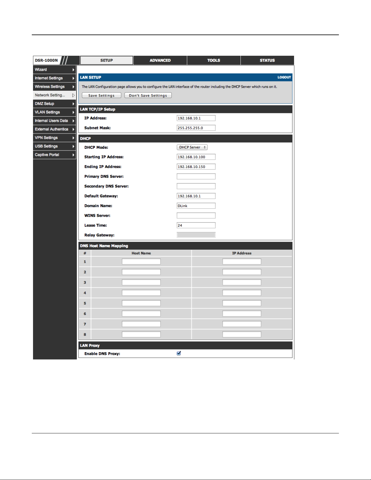
To configure LAN Connectivity, please follow the steps below:
1. In the LAN Setup page, enter the following information for your router:
IP address (factory default: 192.168.10.1).

Unified Services Router User Manual
14
If you change the IP address and click Save Settings, the GUI will not respond. Open a new connection
to the new IP address and log in again. Be sure the LAN host (the machine used to manage the router)
has obtained IP address from newly assigned pool (or has a sta tic IP address in the ro uter’s LAN
subnet) before accessing the router via changed IP address.
Subnet mask (factory default: 255.255.255.0).
2. In the DHCP section, select the DHCP mode:
None: the router’s DHCP server is disabled for the LAN
DHCP Server. With this option the router assigns an IP address within the specified range
plus additional specified information to any LAN device that requests DHCP served
addresses.
DHCP Relay: With this option enabled, DHCP clients on the LAN can receive IP address
leases and corresponding information from a DHCP server on a different subnet. Specify
the Relay Gateway, and when LAN clients make a DHCP request it will be passed along to
the server accessible via the Relay Gateway IP address.
If DHCP is being enabled, enter the following DHCP server parameters:
Starting and Ending IP Addresses: Enter the first and last continuous addresses in the IP
address pool. Any new DHCP client joining the LAN is assigned an IP address in this
range. The default starting address is 192.168.10.2. The default ending address is
192.168.10.100. These addresse s shou ld be in the same IP address subnet as the router’s
LAN IP address. You may wish to save part of the subnet range for devices with statically
assigned IP addresses in the LAN.
Primary and Secondary DNS servers: If configured domain name system (DNS) servers are
available on the LAN enter their IP addresses here.
Default Gateway: By default this setting has the router’s LAN IP address. It can be
customized to any valid IP within the LAN sub ne t, in the e vent that the network’s gateway
is not this router. In this case the DHCP server will give the configured IP address as the
Default Gateway to its DHCP clients.
Domain Name: This is the network domain name used for identification.
WINS Server (optional): Enter the IP address for the WINS server or, if present in your
network, the Windows NetBIOS server.
Lease Time: Enter the time, in hours, for which IP addresses are leased to clients.
Relay Gateway: Enter the gateway address. This is the only configuration parameter
required in this section when DHCP Relay is selected as its DHCP mode
3. In the DNS Host Name Mapping section:

Unified Services Router User Manual
15
Host Name: Provide a valid host name
IP address: Provide the IP address of the host name,
4. In the LAN proxy section:
Enable DNS Proxy: To enable the router to act as a proxy for all DNS requests and
co mmunicate with the ISP’s DNS servers, cl ic k the checkbo x.
5. Click Save Settings to apply all changes.
Unified Services Router User Manual
16
Figure 1: Setup page for LAN TCP/IP settings
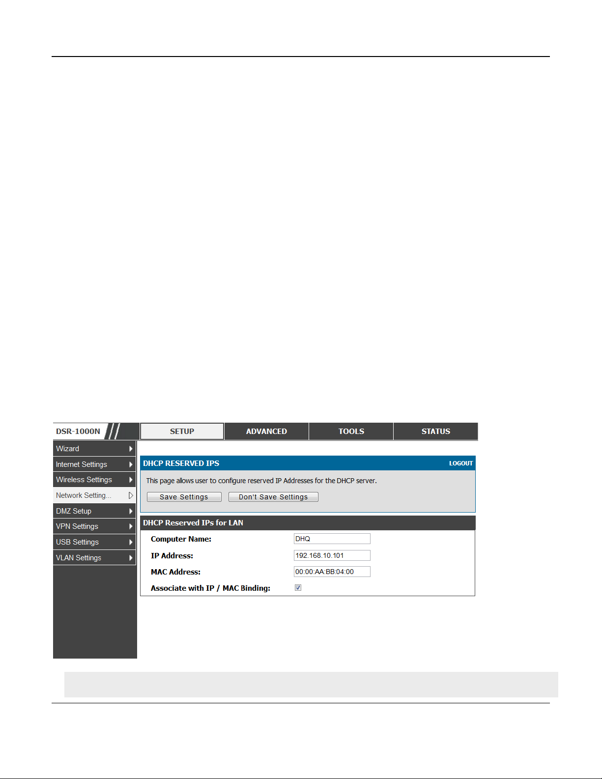
2.1.1 LAN DHCP Reserved IPs
Setup > Network Settings > LAN DHCP Reserved IPs
The router’s DHCP server can assign TCP/IP configurations to computers in the LAN explicitly by
adding client's network interface hardware address and the IP address to be assigned to that client in
DHCP server's database. Whenever DHCP server receives a request from client, hardware address of
Unified Services Router User Manual
17
that client is compared with the hardware address list present in the database, if an IP address is
already assigned to that computer or device in the database , the customized IP address is configured
otherwise an IP address is assigned to the client automatically from the DHCP pool.
Computer Name: The user defined name for the LAN host.
IP Addresses: The LAN IP address of a host that is reserved by the DHCP server.
MAC Addresses: The MAC address that will be assigned the reserved IP address when it is on the
LAN.
Associate with IP/MAC Binding: When the user enables this option the Computer Name, IP and
MAC addresses are associated with the IP/MAC binding.
The actions that can be taken on list of reserved IP addresses are:
Select: Selects all the reserved IP addresses in the list.
Edit: Opens the LAN DHCP Reserved IP Configuration page to edit the selected binding rule.
Delete: Deletes the selected IP address reservation(s)
Add: Opens the LAN DHCP Reserved IP Configuration page to add a new binding rule.
Figure 2: LAN DHCP Reserved IPs
Note the following limits for the number of DHCP Reserved IP addresses per product:
Unified Services Router User Manual
18
o DSR-150/150N: 32
o DSR-250/250N: 64
o DSR-500/500N: 96
o DSR-1000/1000N: 128
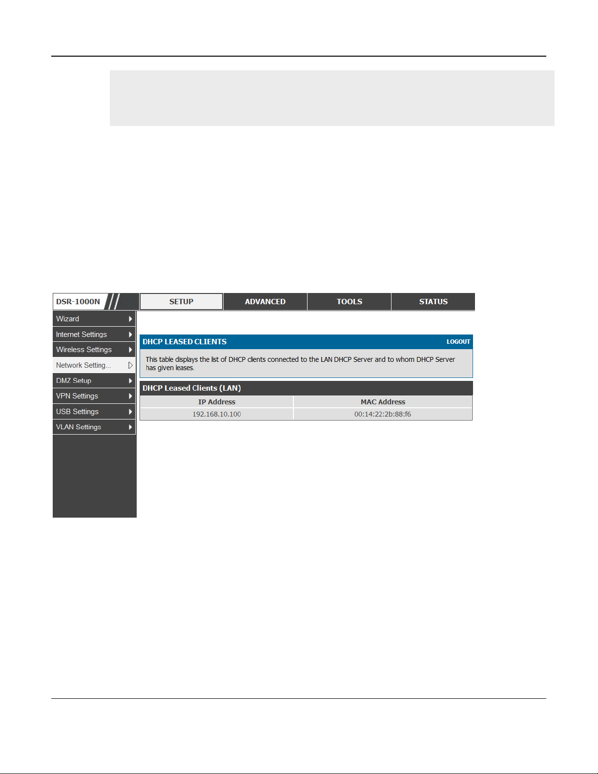
2.1.2 LAN DHCP Leased Clients
Setup > Network Settings > LAN DHCP Leased Clients
This page provides the list of clients connect to LAN DHCP server.
Figure 3: LAN DHCP Leased Clients
IP Addresses: The LAN IP address of a host that matches the reserved IP list.
MAC Addresses: The MAC address of a LAN host that has a configured IP address reservation.
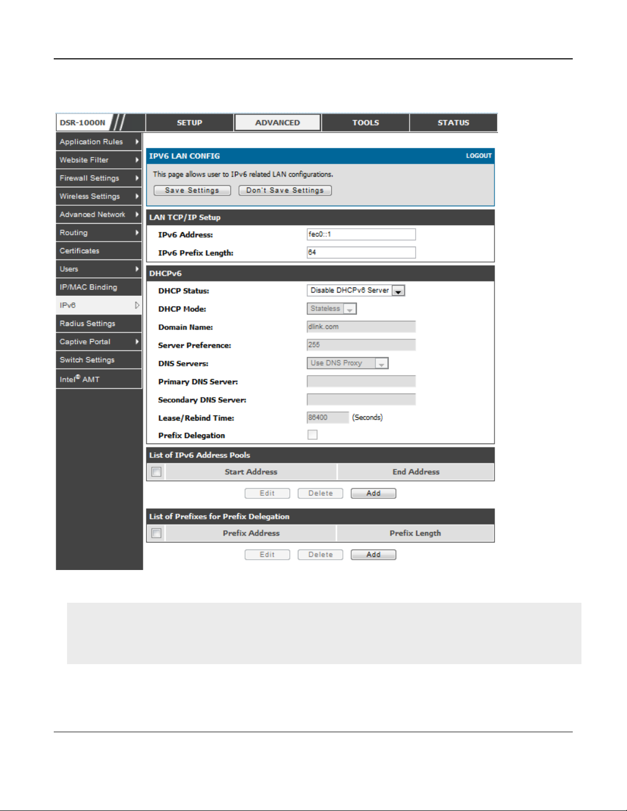
2.1.3 LAN Configuration in an IPv6 Network
Advanced > IPv6 > IPv6 LAN > IPv6 LAN Config
(1) In IPv6 mode, the LAN DHCP server is disabled by default (similar to IPv4 mode). The
DHCPv6 server will serve IPv6 addresses from configured address pools with the IPv6 Prefix
Length assigned to the LAN.

Unified Services Router User Manual
19
IPv4 / IPv6 mode must be enabled in the Advanced > IPv6 > IP mode to enable IPv6 configuration
options.
LAN Settings
The default IPv6 LAN address for the router is fec0::1. You can change this 128 bit IPv6 address
based on your network requirements. The other field that defines the LAN settings for the router is
the prefix length. The IPv6 network (subnet) is identified by the initial bits of the address called the
prefix. By default this is 64 bits long. All hosts in the network have common initial bits for their
IPv6 address; the number of common initial bits in the network’ s address es is set by the prefix
length field.
Unified Services Router User Manual
20
Figure 4: IPv6 LAN and DHCPv6 configuration
If you change the IP address and click Save Settings, the GUI will not respond. Open a new connection
to the new IP address and log in again. Be sure the LAN host (the machine used to manage the router)
has obtained IP address from newly assi gned po ol (or has a static IP address in the router’s LAN
subnet) before accessing the router via changed IP address.
As with an IPv4 LAN network, the router has a DHCPv6 server. If enabled, the router assigns an IP
address within the specified range plus additional specified information to any LAN PC that
requests DHCP served addresses.
The following settings are used to configure the DHCPv6 server:

Unified Services Router User Manual
21
DHCP Mode: The IPv6 DHCP server is either stateless or stateful. If stateless is selected an
external IPv6 DHCP server is not required as the IPv6 LAN hosts are auto-configured by this
router. In this case the router advertisement daemon (RADVD) must be configured on this
device and ICMPv6 router discovery messages are used by the host for auto-configuration.
There are no managed addresses to serve the LAN nodes. If stateful is selected the IPv6 LAN
host will rely on an external DHCPv6 server to provide required configuration settings
The domain name of the DHCPv6 server is an optional setting
Server Preference is used to indicate the preference level of this DHCP server. DHCP advertise
messages with the highest server preference value to a LAN host are preferred over other DHCP
server advertise messages. The default is 255.
The DNS server details can be manually entered here (primary/secondary options. An
alternative is to allow the LAN DHCP client to receive the DNS server details from the ISP
directly. By selecting Use DNS proxy, this router acts as a proxy for all DNS requests and
communicates with the ISP’s DNS server s (a WAN configuration parameter).
Primary and Secondary DNS servers: If there is configured domain name system (DNS) servers
available on the LAN enter the IP addresses here.
Lease/Rebind time sets the duration of the DHCPv6 lease from this router to the LAN client.
IPv6 Address Pools
This feature allows you to define the IPv6 delegation prefix for a range of IP addresses to be served
by the gateway’s D HCPv6 server. Using a delegation prefix you can automate the process of
informing other networking equipment on the LAN of DHCP information specific for the assigned
prefix.
Prefix Delegation
The following settings are used to configure the Prefix Delegation:
Prefix Delegation: Select this option to enable prefix delegation in DHCPv6 server. This option
can be selected only in Stateless Address Auto Configuration mode of DHCPv6 server.
Prefix Address: IPv6 prefix address in the DHCPv6 server prefix pool
Prefix Length: Length prefix address
2.1.4 Configuring IPv6 Router Advertisements
Router Advertisements are analogous to IPv4 DHCP assignments for LAN clients, in that the router
will assign an IP address and supporting network information to devices that are configured to
accept such details. Router Advertisement is required in an IPv6 network is required for stateless
auto configuration of the IPv6 LAN. By configuring the Router Advertisement Daemon on this
router, the DSR will listen on the LAN for router solicitations and respond to these LAN hosts with
router advisements.

Unified Services Router User Manual
22
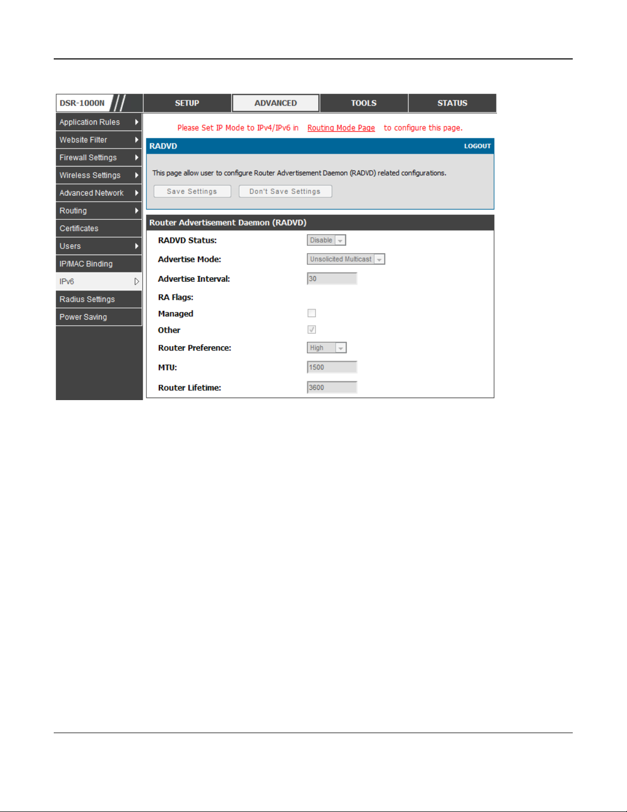
RADVD
Advanced > IPv6 > IPv6 LAN > Router Advertisement
To support stateless IPv6 auto configuration on the LAN, set the RADVD status to Enable. The
following settings are used to configure RADVD:
Advertise Mode: Select Unsolici ted Multicast to send router advertise me nts (RA’s) to all
interfaces in the multicast group. To restrict RA’s to well-known IPv6 addresses on the
LAN, and thereby reduce overall network traffic, select Unicast only.
Advertise Interval: When advertisements are unsolicited multicast packets, this interval sets
the maximum time between advertisements from the interface. The actual duration between
advertisements is a random value between one third of this field and this field. The default
is 30 seconds.
RA Flags: The router advertiseme nts (RA’s) can be sent with one or both of these fla gs.
Chose Managed to use the administered /stateful protocol for address auto configuration. If
the Other flag is selected the host uses administered/stateful protocol for non-address auto
configuration.
Router Preference: this low/medium/high parameter determines the preference associated
with the RADVD process of the router. This is useful if there are other RADVD enabled
devices on the LAN as it helps avoid conflicts for IPv6 clients.
MTU: The router advertisement will set this maximum transmission unit (MTU) value for all
nodes in the LAN that are auto configured by the router. The default is 1500.
Router Lifetime: This value is present in RA’s a nd in dicates the usefulness o f t hi s router as
a default router for the interface. The default is 3600 seconds. Upon expiration of this value,
a new RADVD exchange must take place between the host and this router.
Unified Services Router User Manual
23
Figure 5: Configuring the Router Advertisement Daemon
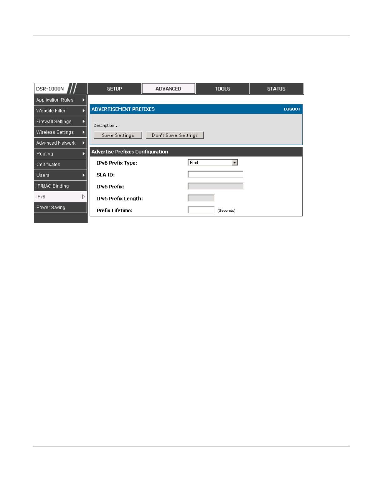
Advertisement Prefixes
Advanced > IPv6 > IPv6 LAN > Advertisement Prefixes
The router advertisements configured with advertisement prefixes allow this router to inform hosts
how to perform stateless address auto configuration. Router advertisements contain a list of subnet
prefixes that allow the router to determine neighbors and whether the host is on the same link as the
router.
The following prefix options are available for the router advertisements:
IPv6 Prefix Type: To ensure hosts support IPv6 to IPv4 tunnel select the 6to4 prefix type.
Selecting Global/Local/ISATAP will allow the nodes to support all other IPv6 routing
options
SLA ID: The SLA ID (Site-Level Aggregation Identifier) is available when 6to4 Prefixes are
selected. This should be the in terface ID of the router’s LAN interface used fo r rout er
advertisements.
IPv6 Prefix: When using Global/Local/ISATAP prefixes, this field is used to define the IPv6
network advertised by this router.
IPv6 Prefix Length: This value indicates the number contiguous, higher order bits of the
IPv6 address that define up the network portion of the address. Typically this is 64.
Unified Services Router User Manual
24
Prefix Lifetime: This defines the duration (in seconds) that the requesting node is allowed to
use the advertised prefix. It is analogous to DHCP lease time in an IPv4 network.
Figure 6: IPv6 Advertisement Prefix settings
2.2 VLAN Configuration
The router supports virtual network isolation on the LAN with the use of VLANs. LAN devices can be
configured to communicate in a sub network defined by VLAN identifiers. LAN ports can be assigned
unique VLAN IDs so that traffic to and from that physical port can be isolated from the general LAN.
VLAN filtering is particularly useful to limit broadcast packets of a device in a large network
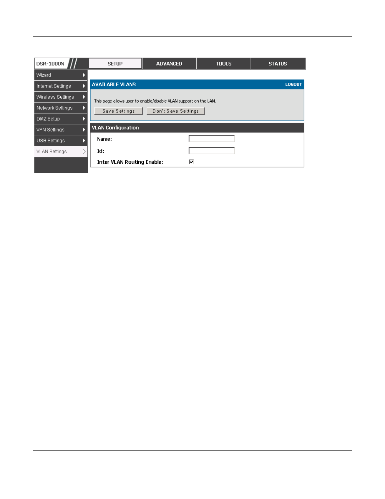
VLAN support is enabled by default in the router. In the VLAN Configuration page, enable VLAN
support on the router and then proceed to the next section to define the virtual network.
Setup > VLAN Settings > Available VLAN
The Available VLAN page shows a list of configured VLANs by name and VLAN ID. A VLAN
membership can be created by clicking the Add button below the List of Available VLANs.
A VLAN membership entry consists of a VLAN identifier and the numerical VLAN ID wh ich is
assigned to the VLAN membership. The VLAN ID value can be any number from 2 to 4091. VLAN
ID 1 is reserved for the default VLAN, which is used for untagged frames received on the interface.
By enabling Inter VLAN Routing, you will allow traffic from LAN hosts belonging to this VLAN ID
to pass through to other configured VLAN IDs that have Inter VLAN Routing enabled.
Unified Services Router User Manual
25
Figure 7: Adding VLAN memberships to the LAN
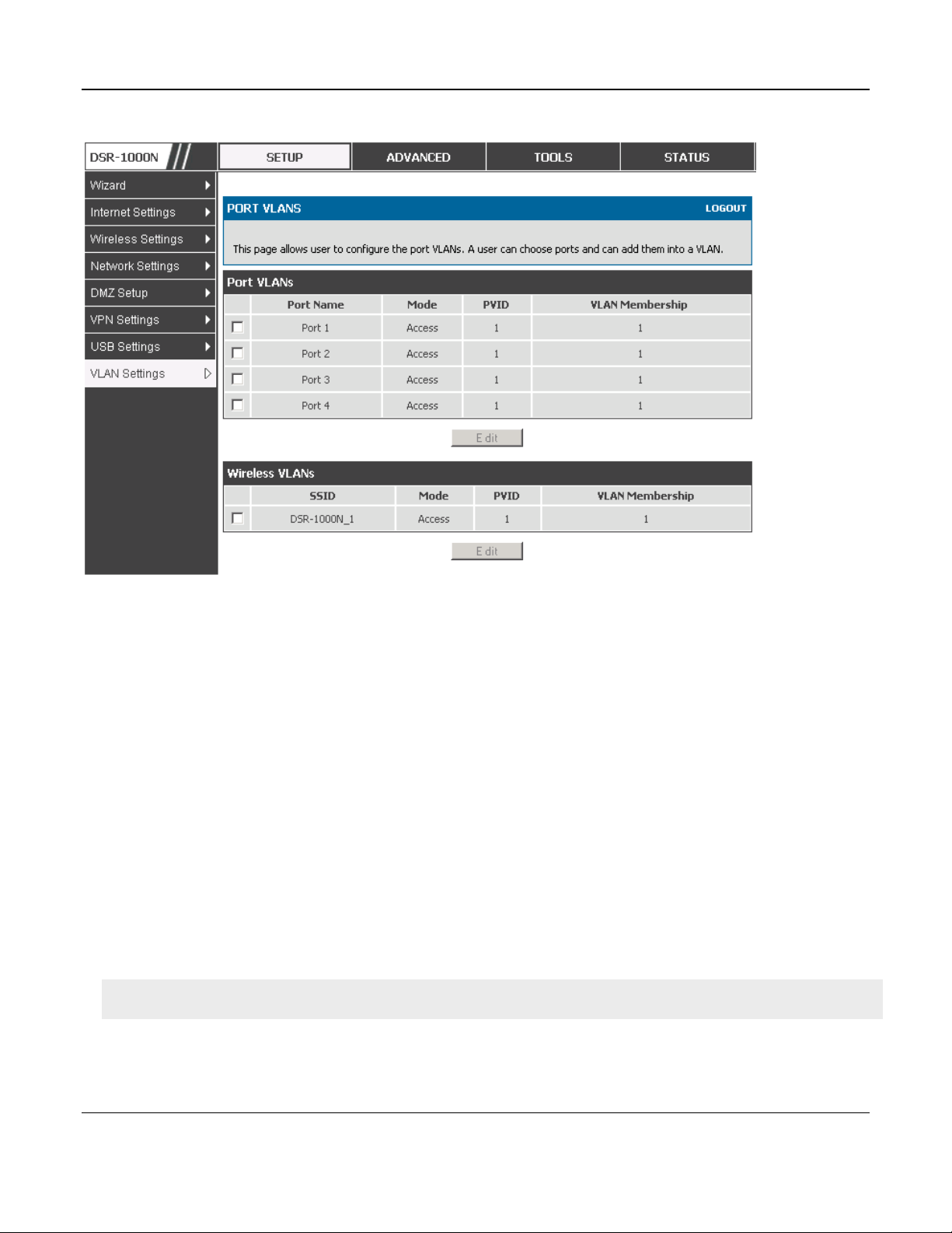
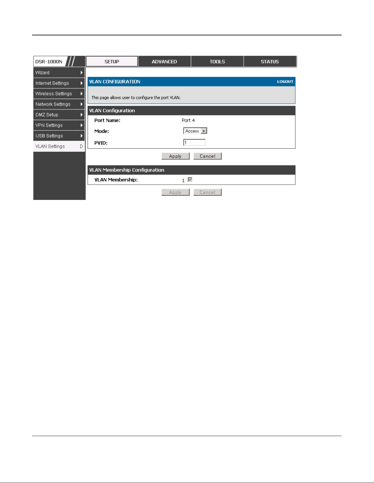
2.2.1 Associating VLANs to ports
In order to tag all traffic through a specific LAN port with a VLAN ID, you can associate a VLAN
to a physical port.
Setup > VLAN Settings > Port VLAN
VLAN membership properties for the LAN and wireless LAN are listed on this page. The VLAN
Port table displays the port identifier, the mode setting for that port and VLAN membership
information. The configuration page is accessed by selecting one of the four physical ports or a
configured access point and clicking Edit.
The edit page offers the following configuration options:
Mode: The mode of this VLAN can be General, Access, or Trunk. The default is access.
In General mode the port is a member of a user selectable set of VLANs. The port sends
and receives data that is tagged or untagged with a VLAN ID. If the data into the port is
untagged, it is assigned the defined PVID. In the configuration from Figure 4, Port 3 is a
General port with PVID 3, so untagged data into Port 3 will be assigned PVID 3. All tagged
data sent out of the port with the same PVID will be untagged. This is mode is typically
used with IP Phones that have dual Ethernet ports. Data coming from phone to the switch
port on the router will be tagged. Data passing through the phone from a connected device
will be untagged.
Unified Services Router User Manual
26
Figure 8: Port VLAN list
In Access mode the port is a member of a single VLAN (and only one). All data going into
and out of the port is untagged. Traffic through a port in access mode looks like any other
Ethernet frame.
In Trunk mode the port is a member of a user selectable set of VLANs. All data going into
and out of the port is tagged. Untagged coming into the port is not forwarded, except for
the default VLAN with PVID=1, which is untagged. Trunk ports multiplex traffic for
multiple VLANs over the same physical link.
Select PVID for the port when the General mode is selected.
Configured VLAN memberships will be displayed on the VLAN Membership Configuration
for the port. By selecting one more VLAN membership options for a General or Trunk port,
traffic can be routed between the selected VLAN membership IDs
The DSR-150 / 150N does not support General mode for port VLANs due to hardware limitations.
Unified Services Router User Manual
27
Figure 9: Configuring VLAN membership for a port
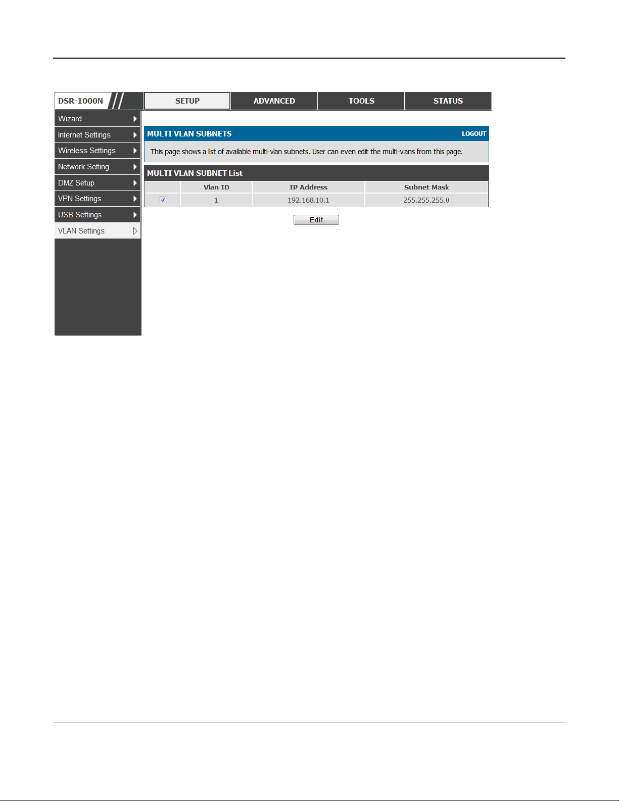
2.2.2 Multiple VLAN Subnets
Setup > VLAN Settings > Multi VLAN Settings
This page shows a list of available multi-VLAN subnets. Each configured VLAN ID can map
directly to a subnet within the LAN. Each LAN port can be assigned a unique IP address and a
VLAN specific DHCP server can be configured to assign IP address leases to devices on this VLAN.
VLAN ID: The PVID of the VLAN that will have all member devices be part of the same subnet
range.
IP Address: The IP address associated with a port assigned this VLAN ID.
Subnet Mask: Subnet Mask for the above IP Address
Unified Services Router User Manual
28
Figure 10: Multiple VLAN Subnets
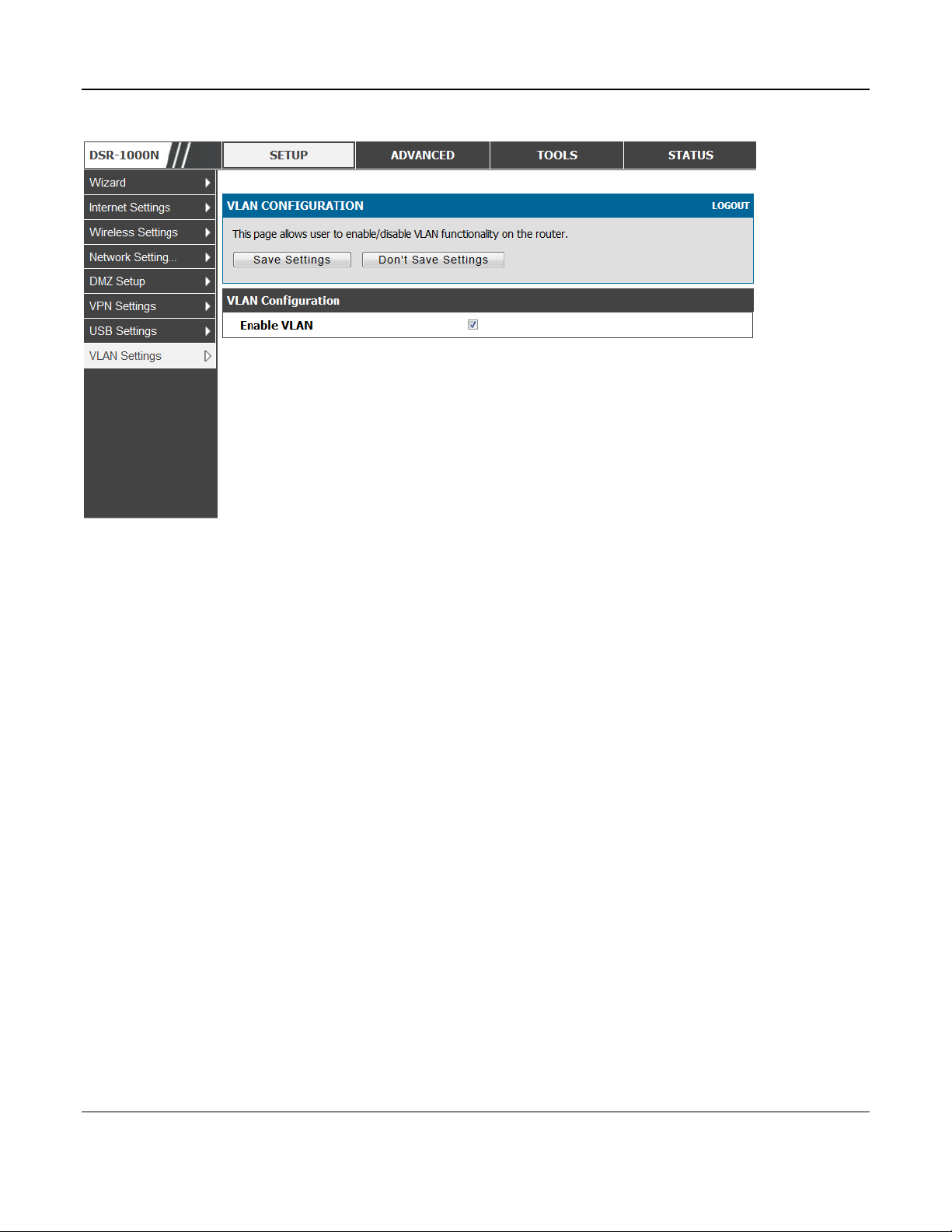
2.2.3 VLAN configuration
Setup > VLAN Settings > VLAN configuration
This page allows enabling or disabling the VLAN function on the router. Virtual LANs can be
created in this router to provide segmentation capabilities for firewall rules and VPN policies. The
LAN network is considered the default VLAN. Check the Enable VLAN box to add VLAN
functionality to the LAN.
Unified Services Router User Manual
29
Figure 11: VLAN Configuration
2.3 Configurable Port: DMZ Setup
This router supports one of the physical ports to be configured as a secondary WAN Ethernet port or a
dedicated DMZ port. A DMZ is a sub network that is open to the public but behind the firewall. The
DMZ adds an additional layer of security to the LAN, as specific services/ports that are exposed to
the internet on the DMZ do not have to be exposed on the LAN. It is recommended that hosts that
must be exposed to the internet (such as web or email servers) be placed in the DMZ network.
Firewall rules can be allowed to permit access specific services/ports to the DMZ from both the LAN
or WAN. In the event of an attack to any of the DMZ nodes, the LAN is not necessarily vulnerable as
well.
Setup > DMZ Setup > DMZ Setup Configuration
DMZ configuration is identical to the LAN configuration. There are no restrictions on the IP address
or subnet assigned to the DMZ port, other than the fact that it cannot be identical to the IP address
given to the LAN interface of this gateway.
 Loading...