


Version 1.0 | 05/29/2013
User Manual
Full HD Outdoor Fixed Dome Network Camera
DCS-6314

Preface
D-Link reserves the right to revise this publication and to make changes in the content hereof without obligation to notify any person or organization of such revisions or changes. Information in this document may become obsolete as our services and websites develop and change.
Manual Revisions
Revision |
Date |
Description |
1.0 |
May 29, 2013 |
DCS-6314 Revision A1 with firmware version 1.00 |
|
|
|
Trademarks
D-Link and the D-Link logo are trademarks or registered trademarks of D-Link Corporation or its subsidiaries in the United States or other countries. All other company or product names mentioned herein are trademarks or registered trademarks of their respective companies.
Copyright © 2013 D-Link Corporation.
All rights reserved. This publication may not be reproduced, in whole or in part, without prior expressed written permission from D-Link Corporation.
D-Link DCS-6314 User Manual |
2 |

Table of Contents
Product Overview......................................................................... |
4 |
Package Contents.................................................................. |
4 |
Introduction............................................................................ |
5 |
System Requirements.......................................................... |
5 |
Features.................................................................................... |
6 |
Hardware Overview.............................................................. |
7 |
Front....................................................................................... |
7 |
Top.......................................................................................... |
8 |
Cable Harness..................................................................... |
9 |
Internal................................................................................ |
10 |
Assembly and Installation........................................................ |
11 |
Installing a Micro SD Card................................................ |
11 |
Deploying the Camera.................................................. |
13 |
Mounting the Camera....................................................... |
15 |
Attaching the Camera to the Pendant Mount...... |
18 |
Attaching the Camera to the Bent Mount.............. |
20 |
Orienting the Camera.................................................... |
22 |
Camera Installation Wizard.............................................. |
23 |
General Connection Using 12 V DC Power |
|
Adapter............................................................................... |
23 |
Connection Using Power over Ethernet.................. |
24 |
Software Installation...................................................... |
25 |
D-ViewCam Setup Wizard............................................. |
28 |
Configuration............................................................................... |
30 |
Using the Configuration Interface................................ |
30 |
Live Video............................................................................... |
31 |
Setup........................................................................................ |
33 |
Setup Wizard..................................................................... |
33 |
Network Setup................................................................. |
39 |
Dynamic DNS.................................................................... |
42 |
Image Setup...................................................................... |
43 |
Audio and Video.............................................................. |
45 |
Preset................................................................................... |
47 |
Motion Detection............................................................ |
49 |
Time and Date.................................................................. |
50 |
Event Setup....................................................................... |
51 |
SD Card................................................................................ |
59 |
Advanced............................................................................... |
60 |
Digital Input/Output...................................................... |
60 |
ICR and IR........................................................................... |
61 |
HTTPS.................................................................................. |
62 |
Access List.......................................................................... |
63 |
Maintenance......................................................................... |
64 |
Device Management...................................................... |
64 |
System................................................................................. |
65 |
Firmware Upgrade.......................................................... |
66 |
Status....................................................................................... |
67 |
Device Info......................................................................... |
67 |
Logs...................................................................................... |
68 |
Help...................................................................................... |
69 |
DI/DO Specifications.................................................................. |
70 |
Technical Specifications............................................................ |
71 |
D-Link DCS-6314 User Manual |
3 |
Section 1: Product Overview
Product Overview
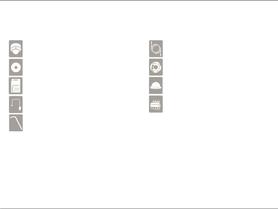
Package Contents
DCS-6314 Full HD Outdoor Fixed Dome Network Camera |
CAT5 Ethernet cable |
CD-ROM with User Manual and software |
Screws and wall socket |
Quick Installation Guide |
Weather Shield |
Power adapter |
4Pin Terminal Block |
Security Wrench |
|
If any of the above items are missing, please contact your reseller.
Note: Using a power supply with a different voltage than the one included with your product will cause damage and void the warranty for this product.
D-Link DCS-6314 User Manual |
4 |

Section 1: Product Overview
Introduction
The DCS-6314 Full HD Outdoor Fixed Dome Network Camera is a professional surveillance and security solution for small, medium, and large enterprises alike. The DCS-6314 uses a 2 megapixel progressive scan CMOS sensor which produces high quality images with low noise, making it ideal for surveillance applications. Together with the WDR enhancement, users can identify image details in both extremely bright as well as dark environments.
The DCS-6314 has an IP68 certified weatherproof housing designed for both indoor and outdoor applications. The built-in removable IR-cut filter and IR LEDs give the DCS-6314 the capability to view up to 15 meters at night. The ability to use Power over Ethernet (PoE) also allows it to be easily installed in a variety of locations without the need for supplemental power cabling. The combination of IP68 housing, IR-Cut Filter, IR LEDs and PoE make the DCS-6314 an ideal solution for a high performance, reliable and cost-effective 24 hour megapixel surveillance solution with an easy clutter-free installation.
System Requirements
•Computer with Microsoft Windows® 8, 7, Vista®, or XP (for CD-ROM Setup Wizard), Mac OS or Linux
•PC with 1.3GHz or above; at least 128MB RAM
•Internet Explorer 7 or above , Firefox 3.5 or above, Safari 4 and Chrome 8.0 or above
•Existing 10/100 Ethernet-based network
•A Micro SD memory card (optional) is required for recording to onboard storage. SDHC Class 6 or above is recommended.
•Broadband Internet connection
D-Link DCS-6314 User Manual |
5 |

Section 1: Product Overview
Features
Wide Dynamic Range
Wide Dynamic Range technology corrects imperfect lighting conditions, providing clear images with the right amount of contrast even when a subject is backlit
Remote Monitoring Utility
The D-ViewCam application adds enhanced features and functionality for the Network Camera and allows administrators to configure and access the Network Camera from a remote site via Intranet or Internet. Other features include image monitoring, recording images to a hard drive, viewing up to 32 cameras on one screen, and taking snapshots.
IR LED for Day and Night Functionality
The built-in infrared LEDs enables night time viewing of up to 15 meters (49 feet).
IP68 Weatherproof Housing
The DCS-6314 uses an IP68 weatherproof housing, allowing you to rest assured that in the toughest of conditions, it will continue to provide round- the-clock surveillance.
PoE (Power over Ethernet) for Flexible Installation
The DCS-6314 can get all the power it needs from a PoE switch or PoE injector for a simple and clutter-free installation.
D-Link DCS-6314 User Manual |
6 |
Section 1: Product Overview
Hardware Overview
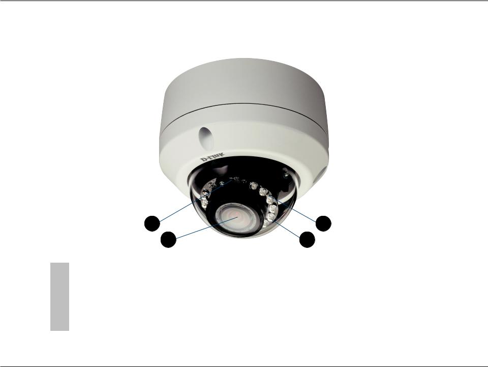
Front
|
1 |
|
4 |
|
|
2 |
3 |
|
|
|
|
1 |
Light Sensor |
The light sensor measures the lighting conditions and switches between color |
|
and infrared accordingly |
|
||
|
|
|
|
|
|
|
|
2 |
Camera Lens |
Vari-focal lens to record video of the surrounding area |
|
|
|
|
|
3 |
IR LEDs |
Infrared LEDs illuminate the camera's field of view at night |
|
|
|
|
|
4 |
Power/Status LED |
Indicates the camera's current status |
|
|
|
|
|
D-Link DCS-6314 User Manual |
7 |
Section 1: Product Overview
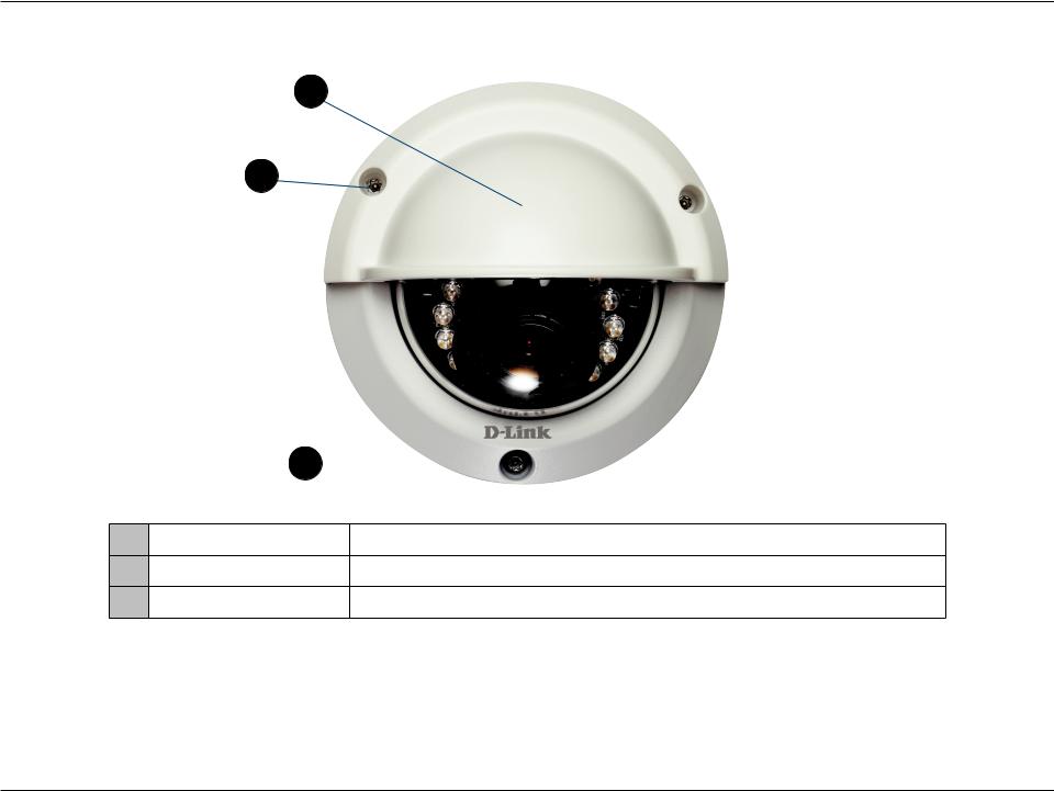
Top
1
2
3 
1Weather Shield Shields the camera sensor from direct sunlight.
2Adjustment Screw Used to secure the weather shield to the camera.
3Bottom Camera Shoe Used to attach to the optional mounting accessories.
Note: When the weathershield is attached, the camera video may show reflections when the IR LEDs are on and the camera is at a high angle. If you experience this, it is recommended that you lower the angle of the camera or turn off the IR LEDs. For details on how to adjust the camera angle, please see "Orienting the Camera" on page 22. For details on how to turn the IR LEDs on/off, please see "ICR and IR" on page 61.
D-Link DCS-6314 User Manual |
8 |
Section 1: Product Overview
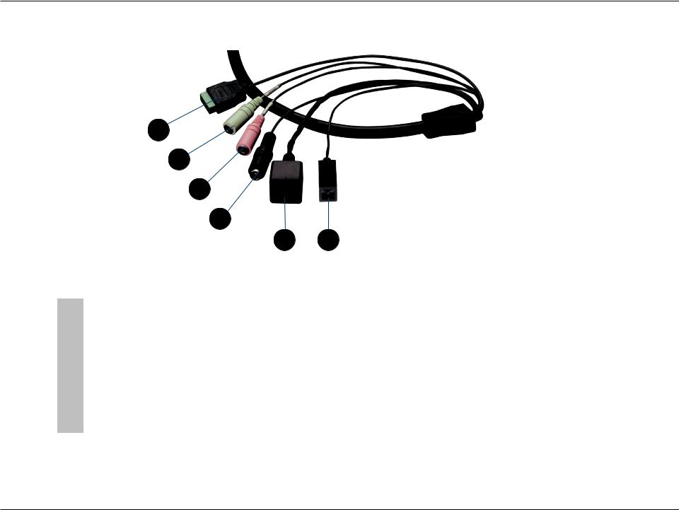
Cable Harness
1
2
3
4
5 6
1 |
DI/DO Connector |
I/O connectors for external devices. 12V DC output. |
|
|
|
|
|
2 |
Audio Out (Green) |
Connects to a speaker. |
|
|
|
|
|
3 |
Audio In (Red) |
Connects to a microphone. |
|
|
|
|
|
4 |
Power Connector |
Power connector for the provided 12V DC power adapter. |
|
|
|
|
|
5 |
Ethernet Jack |
Connects to an RJ45 Ethernet port. Can be used with PoE to provide power to |
|
the camera. |
|||
|
|
||
|
|
|
|
6 |
Reset Button |
Press and hold the recessed button for 10 seconds to reset the camera. |
|
|
|
|
D-Link DCS-6314 User Manual |
9 |
Section 1: Product Overview
Internal
1
1 |
Micro SD Card Slot |
Insert a Micro SD card for Local storage for storing recorded image and video |
|
|
|
Note: For step-by-step instruction on how to insert a Micro SD card please skip to "Installing a Micro SD Card" on page 11.
D-Link DCS-6314 User Manual |
10 |
Section 2: Assembly and Installation
Assembly and Installation
Installing a Micro SD Card
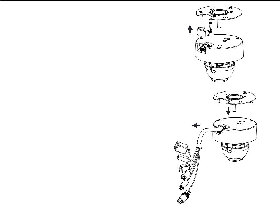
Step 1
Place the camera face down on a non-slip flat surface.
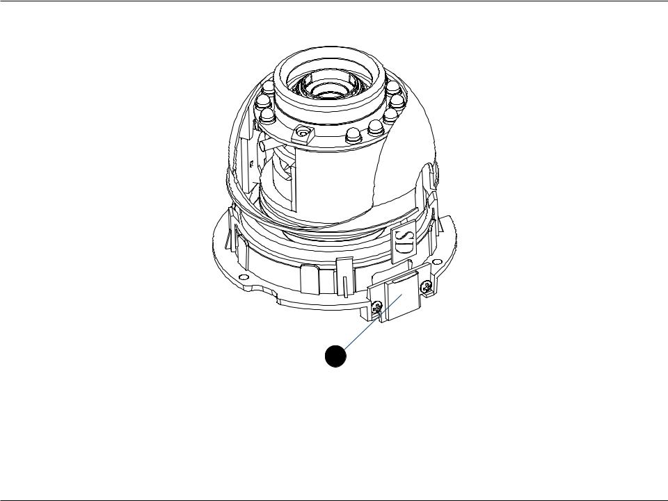
Step 2
Remove the adjustable top part of the camera housing by removing the three retaining screws.
Step 3
Remove the base of the camera by holding the camera firmly and rotating the base in a counter clockwise direction.
D-Link DCS-6314 User Manual |
11 |

Section 2: Assembly and Installation
Step 4
Insert your Micro SD memory card into the slot with the notch oriented to the front of the camera.
Step 5
Replace the base of the camera by holding the camera firmly and rotating the base in a clockwise direction ensuring a tight fit.
Note: Users are advised to ensure that the weatherproof seals are secured firmly in place.
D-Link DCS-6314 User Manual |
12 |
Section 2: Assembly and Installation
Deploying the Camera
Note: Before deploying the camera to a fixed location, it is recommended that you take a photo from the desired location to ensure an adequate field-of-view.
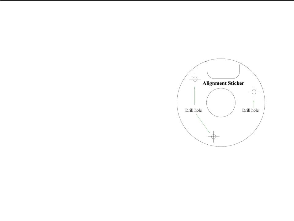
Step 1
Position the Alignment Sticker in the desired location making sure the Camera and Wire-in-Bracket have sufficient space. Use the dimension diagrams in "Dimensions" on page 73 for additional reference.
Step 2
Use a 6mm drill bit to make required holes approximately 30mm deep.
Step 3
Remove the Alignment Sticker.
Step 4
Insert wall anchors and affix the mounting plate using the screws provided.
D-Link DCS-6314 User Manual |
13 |
Section 2: Assembly and Installation
Step 5
Fasten the camera firmly to the mounting plate using the screw provided ensuring clear passage for the cables through the cable channel or via the mounting plate cut-out.
D-Link DCS-6314 User Manual |
14 |
Section 2: Assembly and Installation
Mounting the Camera
The DCS-6314 is suitable for mounting to a wall using the camera shoe and wire-in bracket provided.
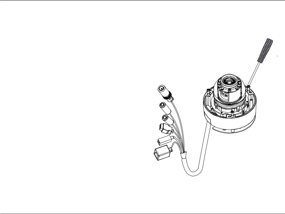
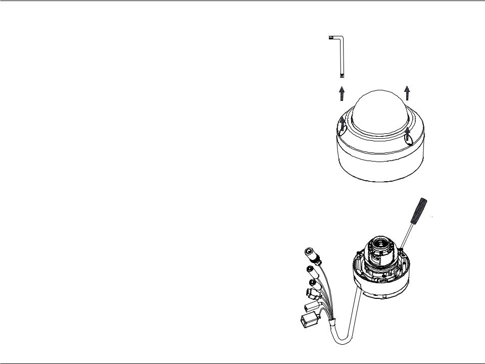
Step 1
Remove the top part of the camera housing by using the included tool to unscrew the three retaining screws.
Step 2
Once the cover has been removed, use a screwdriver to remove the bottom mounting plate from the lower half of the camera housing.The mounting plate is secured with three screws positioned around the outer edge of the lower part of the camera housing.
If you will be mounting the camera directly to a wall or ceiling, please continue to the next page.
If you will be mounting the camera using the pendant mount, please refer to "Attaching the Camera to the Pendant Mount" on page 18.
If you will be mounting the camera using the bent mount, please refer to "Attaching the Camera to the Bent Mount" on page 20.
D-Link DCS-6314 User Manual |
15 |
Section 2: Assembly and Installation
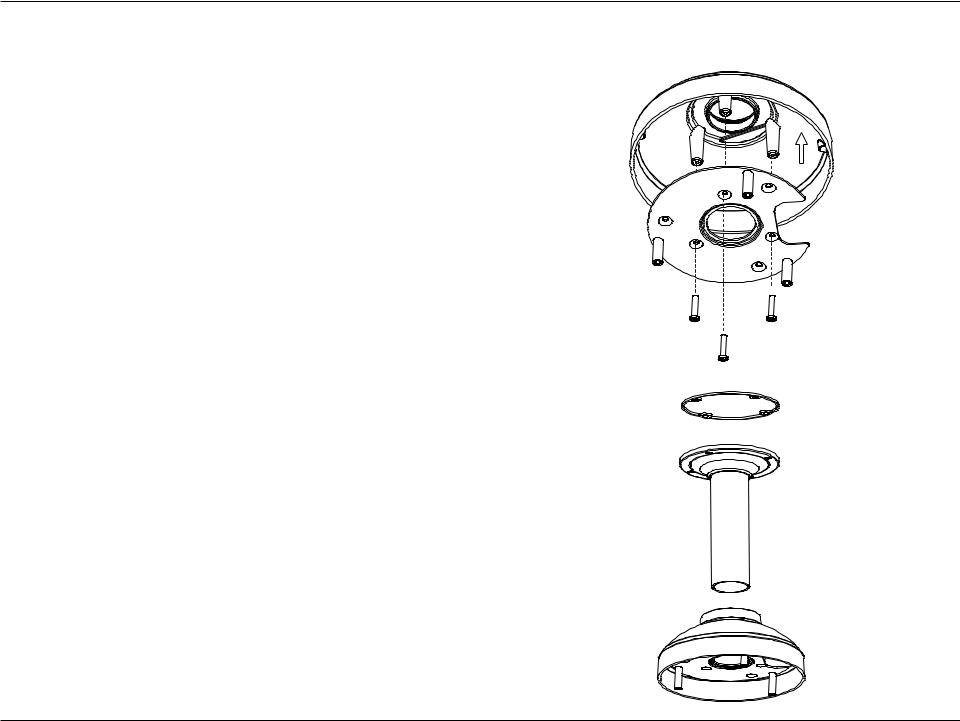
Step 3
Remove the mounting plate from the lower half of the camera housing. It can now be attached to a wall or ceiling using the mounting guide. Please see "Deploying the Camera" on page 13 for more instructions.
If you will be installing the camera onto a surface that cannot house the cable, the cable access part can be removed so that the cable can exit the camera housing easily. Once the mounting plate has been removed, you will be able to remove the cable access panel. If you will be routing the connection cables through a wall or ceiling, it is recommended to leave this part attached, as it will help protect the cable from vandalism.
Step 4
Slide the lower half of the camera housing onto the mounting plate and resecure it. Make sure that the cable sheath extends out of the base in such a way that the cable is not kinked or twisted.
D-Link DCS-6314 User Manual |
16 |

Section 2: Assembly and Installation
Step 5
Reattach the top part of the camera housing, and secure it by tightening the three retaining screws.
Step 6
If necessary, the included weather shield can now be attached to the camera.
D-Link DCS-6314 User Manual |
17 |
Section 2: Assembly and Installation
Attaching the Camera to the Pendant Mount
Step 1
Begin by attaching the mounting plate that was removed from the lower part of the camera housing into the bracket cap.
Step 2
Place the rubber seal onto the mounting part of the pendant bracket. Use the included mounting guide to mark out on the ceiling the proper placement of the mounting holes. Securely mount the rubber seal and pendant bracket to the ceiling, if you need more details please see "Deploying the Camera" on page 13.
Step 3
Attach the bracket cap, by screwing it onto the pendant bracket.
Bracket Cap
Mounting Plate
Rubber Seal
Pendant Bracket
Bracket Cap
D-Link DCS-6314 User Manual |
18 |
Section 2: Assembly and Installation
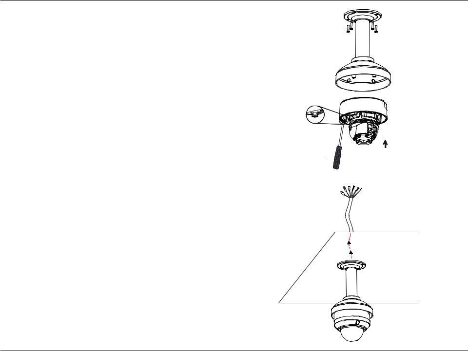
Step 4
Begin the process of reattaching the bottom part of the camera housing, by first pushing the cable sheath up through the pendant mount. Once the cable has been pushed through, you can then firmly reattach the bottom part of the camera housing, and secure it by tightening the three retaining screws.
Dome
Camera
Step 5
Reattach the top part of the camera housing, and secure it by tightening the three retaining screws.
If necessary, the included weather shield can now be attached to the camera. Please see step 6 of "Mounting the Camera" on page 15 for more details on how to do this.
D-Link DCS-6314 User Manual |
19 |
Section 2: Assembly and Installation
Attaching the Camera to the Bent Mount
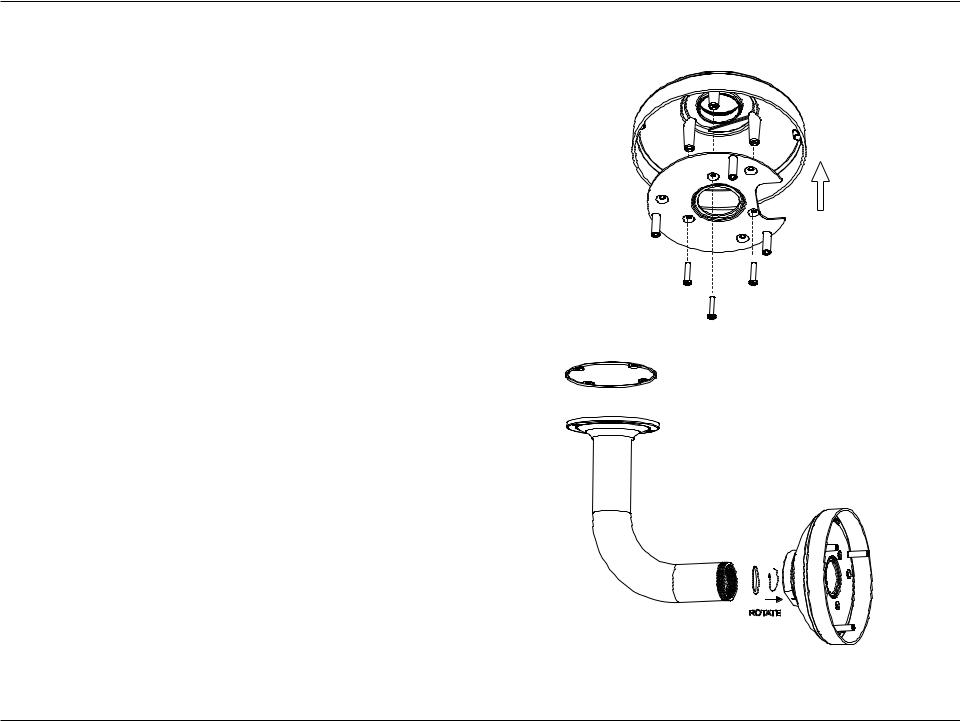
Step 1
Begin by attaching the mounting plate that was removed from the lower part of the camera housing into the bracket cap.
Step 2
Mounting
Place the rubber seal onto the mounting part of the bent Plate bracket. Use the included mounting guide to mark out on
the ceiling the proper placement of the mounting holes. Securely mount the rubber seal and pendant bracket to the ceiling, if you need more details please see "Deploying the Camera" on page 13.
Bracket
Cap
Step 3
Attach the bracket cap, by screwing it onto the pendant bracket.
Bent
Bracket
Bracket
Cap
D-Link DCS-6314 User Manual |
20 |
Section 2: Assembly and Installation
Step 4
Begin the process of reattaching the bottom part of the camera housing, by first pushing the cable sheath up through the bent mount. Once the cable has been pushed through, you can then firmly reattach the bottom part of the camera housing, and secure it by tightening the three retaining screws.
Dome
Camera
Step 5
Reattach the top part of the camera housing, and secure it by tightening the three retaining screws.
If necessary, the included weather shield can now be attached to the camera. Please see step 6 of "Mounting the Camera" on page 15 for more details on how to do this.
D-Link DCS-6314 User Manual |
21 |
Section 2: Assembly and Installation
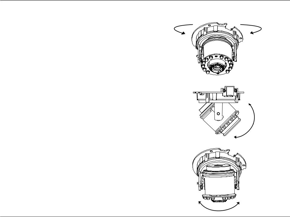
Orienting the Camera
The DCS-6314 can be adjusted to ensure an optimal viewing position when mounted to a wall by following the steps outlined.
Step 1
Turn the lens module left and right until the desired position is achieved.
Step 2
Loosen the tilt screws on both sides of the camera, and turn the lens module up and down until the desired position is achieved.
Step 3
Turn the lens to adjust the IP camera’s image until the desired orientation is achieved.
D-Link DCS-6314 User Manual |
22 |
 Loading...