


Quick Installation Guide
This document will guide you through the basic installation process for your new D-Link Unmanaged Switch.
DSS-100E-9P
INSTALLATIONSANLEITUNG
GUIDE D’INSTALLATION
GUÍA DE INSTALACIÓN
GUIDA DI INSTALLAZIONE
Documentation is also available on the D-Link website

ENGLISH
Before You Begin
This Quick Installation Guide gives you step-by-step instructions for setting up your DSS-100E-9P 9-port 10/100 PoE Surveillance Switch.The model you have purchased may appear slightly different from the one shown in the illustrations.
Package Contents
This DSS-100E-9P package should include the following items:
•1 x DSS-100E-9P
•1 x Power cord
•1 x Power adaptor
•1 x Quick Installation Guide
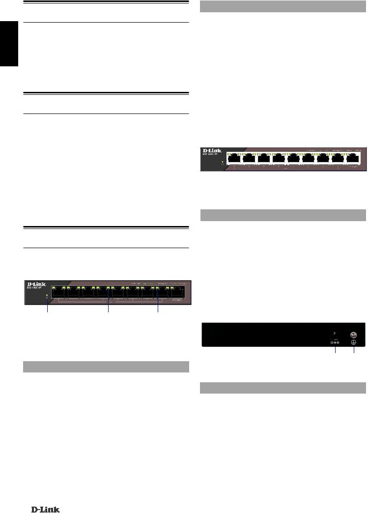
Front Panel Connectors
|
|
|
|
|
|
|
|
|
|
|
|
|
|
|
|
|
|
|
|
|
|
|
|
|
|
|
|
|
|
|
|
|
|
|
|
|
|
|
|
|
|
|
|
|
|
|
|
|
|
|
|
|
|
|
|
|
|
|
|
|
|
|
|
|
|
|
|
|
|
|
|
|
|
|
|
|
|
|
|
|
|
|
|
|
|
|
|
|
|
|
|
|
|
|
|
|
|
|
|
|
|
|
|
|
|
|
|
|
|
1 |
|
2 |
|
|
||
|
|
|
|
|
Figure 2: Front panel connectors |
|
|
|
|
|||
|
|
|
|
|
|
|
|
|
|
|
|
|
|
# |
|
Interface |
|
Description |
|
|
|
|
|||
|
|
|
Ports 1 - 8 |
10/100 Mbps PoE-capable ports, |
|
|||||||
|
1 |
|
used for connecting Ethernet |
|
|
|
|
|||||
|
|
|
|
|
|
devices and PoE-powered devices. |
|
|||||
|
|
|
|
Ports 9 |
10/100/1000 Mbps Ethernet |
|
|
|
|
|||
|
2 |
|
|
port for uplink connections to |
|
|
|
|
||||
|
|
|
|
|
|
NVR, storage or core switch. |
|
|
|
|
||
Table 2: Front connector description
Rear Panel Connectors
If any of the above items are damaged or missing, please contact your local D-Link reseller.
Hardware Overview
LED Indicators
|
|
|
|
|
|
|
|
|
|
|
|
|
|
|
|
|
|
|
|
|
|
|
|
|
|
|
|
|
|
|
|
|
|
|
|
|
|
|
|
|
|
|
|
|
|
|
|
|
|
|
|
|
|
|
|
|
|
|
|
|
|
|
|
|
|
|
|
|
|
|
|
|
|
|
|
|
|
|
|
|
|
|
|
|
|
|
|
|
|
|
|
|
|
|
|
|
|
1 |
|
|
2 |
|
3 |
|
|||
|
|
|
|
|
Figure 1: Front panel LEDs |
|
|
|
|||
|
|
|
|
|
|
|
|
|
|
|
|
|
# |
LED |
Status |
|
|
Description |
|
||||
|
|
|
|
|
Solid |
The switch is powered on. |
|
||||
|
1 |
Power |
green |
|
|
|
|
|
|
||
|
|
|
|
|
Off |
The switch is turned off. |
|
||||
|
|
Link/ |
Solid |
There is an active link negotiated |
|
||||||
|
|
green |
on this port. |
|
|
|
|||||
|
|
ACT/ |
|
|
|
||||||
|
2 |
Speed |
Blinking |
There is traffic on the port. |
|
||||||
|
|
(Left |
green |
|
|
|
|
|
|
||
|
|
Led) |
|
|
|
|
|
|
|
||
|
|
Off |
There is no active link on this port. |
|
|||||||
|
|
|
|
|
|
||||||
|
|
|
|
|
Solid |
The port is providing power to the |
|
||||
|
|
|
|
|
green |
connected PoE-powered device. |
|
||||
|
|
|
PoE |
Blinking |
Indicates a PoE-powered device |
|
|||||
|
|
|
green |
is connected to this PoE port, |
|
||||||
|
3 |
(Right |
|
but the switch has insufficient |
|
||||||
|
|
Led) |
|
remaining power budget to |
|
||||||
|
|
|
|
|
|
power the device. |
|
|
|
||
|
|
|
|
|
Off |
There is no PoE-powered device |
|
||||
|
|
|
|
|
|
connected to this port. |
|
||||
Table 1: LED overview
|
Figure 3: Rear panel connectors |
1 |
2 |
||
|
|
|
|||
|
|
|
|
|
|
# |
Connector |
Description |
|
|
|
1 |
DC Power Input |
Input jack for the power adapter. |
|||
2 |
SWITCH GND |
Screw used to secure a grounding |
|||
wire to connect the switch to ground. |
|||||
|
|
||||
|
Table 3: Rear connector description |
|
|||
Extended Mode
The DSS-100E-9P can automatically detect the long reach requirement and activate Extended without manual configuration.
P.S. The actual transmission distance will be affected by cable quality or connected IP Camera design. The device can support up to 250m application with Cat5e above ethernet cable, but the transmission may drop to 10Mbps speed or below.
Hardware Installation
Installation Precautions
For safe switch installation and operation, it is recommended to:
2 |
DSS-100E-9P |

•Visually inspect the DC power jack and make sure that it is fully secured to the power adapter.
•Make sure that there is proper heat dissipation and adequate ventilation around the switch.
•Install the switch in a site free from strong electromagnetic sources, vibration, dust, and direct sunlight.
•Not place heavy objects on the switch.
Grounding the Switch
The following steps explain the procedure for connecting the switch to a protective ground:
1.Verify that the system is powered off.
2.Remove the ground screw and place the #8 terminal lug ring at one end of the ground cable on top of the ground screw opening.
3.Insert the ground screw back into the ground screw opening.
4.Using a screwdriver, tighten the ground screw to secure the ground cable to the switch.
5.Attach the terminal lug ring at the other end of the grounding cable to an appropriate grounding source.
6.Verify that the connections from the ground connector on the switch to the grounding source are securely attached.
Powering On the Switch
After connecting the switch to the network using a compatible category 5/6/7 UTP network cable, simply connect the switch to a power outlet to power the device.
TECHNICAL SUPPORT |
dlink.com/support |
|
|
ENGLISH
DSS-100E-9P |
3 |
|
|
DEUTSCH
Vor der Inbetriebnahme
In dieser Installationsanleitung erhalten Sie schrittweise Anweisungen zur Einrichtung Ihres DSS-100E-9P 9-port 10/100 PoE Surveillance Switch. Beachten Sie, dass das von Ihnen erworbene Modell sich möglicherweise geringfügig von denen der Abbildungen unterscheidet.
Packungsinhalt
DiesesDSS-100E-9P-PaketmussFolgendesenthalten:
•1 x DSS-100E-9P
•1 x Netzkabel
•1 x Netzteil
•1 x Installationsanleitung
Sollte eines der oben aufgeführten Teile beschädigt sein oder fehlen, wenden Sie sich bitte an Ihren D-Link-Händler vor Ort.
Hardware-Übersicht
LED-Anzeigen
1 |
2 |
3 |
Abbildung 1: Vorderseite LEDs
Nr. |
LED |
Status |
Beschreibung |
|
|
|
Konstant |
Der Switch ist eingeschaltet. |
|
1 |
Strom |
grün |
|
|
|
|
Aus |
Der Switch ist ausgeschaltet. |
|
|
Link/ |
Konstant |
Für diesen Port ist eine aktive |
|
|
grün |
Verknüpfung gewählt. |
||
|
ACT/ |
|
|
|
|
Grün |
Über den Port wird Datenverkehr |
||
2 |
Speed |
|||
blinkend |
geleitet. |
|||
|
(Linke |
|||
|
Aus |
An diesem Port besteht keine |
||
|
LED) |
|||
|
|
|
aktive Verbindung. |
Nr. |
LED |
Status |
Beschreibung |
|
|
Konstant |
D a s ü b e r Po E g e s p e i s t e |
|
|
grün |
angeschlossene Gerät wird über |
|
|
|
den Port mit Strom versorgt. |
|
PoE |
Grün |
Zeigt an, dass ein PoE-gespeistes |
|
blinkend |
Gerät an diesem PoE-Por t |
|
3 |
(Rechte |
|
angeschlossen, das verbleibende |
|
LED) |
|
Strombudget des Switch für die |
|
|
|
Versorgung des Geräts aber nicht |
|
|
|
ausreichend ist. |
|
|
Aus |
An diesem Port ist kein PoE- |
|
|
|
gespeistes Gerät angeschlossen. |
Tabelle 1: LED-Übersicht
Anschlüsse an der Vorderseite
|
|
|
|
|
|
|
|
|
|
|
|
|
|
|
|
|
|
|
|
|
|
|
|
|
|
|
|
|
|
|
|
|
|
|
|
|
|
|
|
|
|
|
|
|
|
|
|
|
|
|
|
|
|
|
|
|
|
|
|
|
|
|
|
|
|
|
|
|
|
|
|
|
|
|
|
|
|
|
|
|
|
|
|
|
|
|
|
|
|
|
|
|
|
|
|
|
|
|
|
|
|
|
|
|
|
|
|
|
|
1 |
|
2 |
|
|
||
|
Abbildung 2: Anschlüsse an der Vorderseite |
|
|
|
|
|||||||
|
|
|
|
|
|
|
|
|
|
|
|
|
Nr. |
Schnittstelle |
|
Beschreibung |
|
|
|
|
|||||
|
|
|
|
|
|
10/100 Mbit/s PoE-fähige Ports, |
|
|||||
1 |
|
Ports 1 - 8 |
verwendet für den Anschluss |
|
|
|
|
|||||
|
von Ethernet-Geräten und |
|
|
|
|
|||||||
|
|
|
|
|
|
|
|
|
|
|||
|
|
|
|
|
|
PoE-betriebenen Geräten. |
|
|
|
|
||
|
|
|
Port 9 |
10/100/1000 Mbit/s Ethernet-Port |
|
|||||||
2 |
|
|
für Uplink-Verbindungen zu NVR, |
|
||||||||
|
|
|
|
|
|
Speichergerät oder Core-Switch. |
|
|||||
Tabelle 2: Beschreibungen der vorderen Anschlüsse
Anschlüsse an der Rückseite
|
|
1 |
2 |
|
Abbildung 3: Anschlüsse an der Rückseite |
|
|
|
|
|
|
Nr. |
Anschluss |
Beschreibung |
|
1 |
DC- |
Buchse zum Anschließen des |
|
Stromversorgung |
Netzteils. |
|
|
|
|
||
|
SWITCH GND |
Schraube zum Anschließen eines |
|
2 |
Erdungsdrahts zum Verbinden |
||
|
|
des Switch mit Erde. |
|
Tabelle 3: Beschreibungen der hinteren Anschlüsse
4 |
DSS-100E-9P |
|
|
 Loading...