


4900
Table of contents
 Loading...
Installing Avaya Ethernet Routing Switch
4900 Series
Release 7.1
NN47212-301
Issue 01.02
February 2016

Contents
Chapter 1: Introduction............................................................................................................ 4
Purpose.................................................................................................................................. 4
Related resources................................................................................................................... 4
Searching a documentation collection................................................................................. 5
Subscribing to e-notifications.............................................................................................. 6
Support.................................................................................................................................. 8
Chapter 2: New in this document............................................................................................ 9
Chapter 3: Preinstallation checklist...................................................................................... 10
Chapter 4: Installing Ethernet Routing Switch 4900 Series................................................ 12
Installation checklist............................................................................................................... 12
Ethernet Routing Switch 4900 Series models.......................................................................... 12
Common hardware features............................................................................................. 14
Electrostatic discharge prevention.......................................................................................... 15
Technical specifications......................................................................................................... 16
Power specifications........................................................................................................ 17
MTBF values................................................................................................................... 19
AC power cord specifications........................................................................................... 20
Universal Serial Bus ports...................................................................................................... 21
Connector pin assignments.................................................................................................... 21
RJ-45 connector pin assignments for PoE switches........................................................... 21
Console port pin assignments.......................................................................................... 22
Equipment requirement.......................................................................................................... 22
Verifying the package contents......................................................................................... 22
Cable requirements......................................................................................................... 25
Switch installation.................................................................................................................. 26
Installing the switch in an equipment rack.......................................................................... 26
Installing optional four-post rack-mount brackets................................................................ 30
Installing the secondary power supply............................................................................... 34
Connecting switch to AC power........................................................................................ 35
Connecting a transceiver to the switch or switch stack.............................................................. 35
Installing SFP transceivers............................................................................................... 36
Removing of SFP transceivers......................................................................................... 37
Supported optical devices ............................................................................................... 38
Stacking............................................................................................................................... 42
Connecting switches in a stack......................................................................................... 46
Stack configurations........................................................................................................ 46
Replacing or adding a stack unit....................................................................................... 49
Removing a stack unit..................................................................................................... 49
Checking Light Emitting Diode on the switch............................................................................ 49
February 2016 Installing Avaya Ethernet Routing Switch 4900 Series 2
Comments on this document? infodev@avaya.com

Contents
Switch LED state indicators.............................................................................................. 50
Port LED state indicators................................................................................................. 51
Appendix A: Translations of safety messages.................................................................... 53
Safety messages................................................................................................................... 53
February 2016 Installing Avaya Ethernet Routing Switch 4900 Series 3
Comments on this document? infodev@avaya.com

Chapter 1: Introduction
Purpose
This document provides the information and procedures required to install the hardware, software,
cabling, and power for the Ethernet Routing Switch 4900 Series.
Unless otherwise indicated, this information applies to:
• ERS 4950GTS
• ERS 4926GTS
• ERS 4950GTS-PWR+
• ERS 4926GTS-PWR+
Related resources
Documentation
For a list of the documentation for this product and more information about documents on how to
configure other switch features, see Documentation Reference for Avaya Ethernet Routing Switch
4900 and 5900 Series, NN47211-103.
For more information on new features of the switch and important information about the latest
release, see Release Notes for Avaya Ethernet Routing Switch 4900 and 5900 Series,
NN47211-400.
For more information about how to configure security, see Configuring Security on Avaya Ethernet
Routing Switch 4900 and 5900 Series, NN47211-505.
For the current documentation, see the Avaya Support web site:
Training
Ongoing product training is available. For more information or to register, see http://avaya-
learning.com/.
www.avaya.com/support.
February 2016 Installing Avaya Ethernet Routing Switch 4900 Series 4
Comments on this document? infodev@avaya.com

Related resources
Enter the course code in the Search field and click Go to search for the course.
Course code Course title
8D00020E Stackable ERS and VSP Products Virtual Campus Offering
Viewing Avaya Mentor videos
Avaya Mentor videos provide technical content on how to install, configure, and troubleshoot Avaya
products.
About this task
Videos are available on the Avaya Support website, listed under the video document type, and on
the Avaya-run channel on YouTube.
Procedure
• To find videos on the Avaya Support website, go to
of the following actions:
- In Search, type Avaya Mentor Videos to see a list of the available videos.
- In Search, type the product name. On the Search Results page, select Video in the
Content Type column on the left.
• To find the Avaya Mentor videos on YouTube, go to
perform one of the following actions:
- Enter a key word or key words in the Search Channel to search for a specific product or
topic.
- Scroll down Playlists, and click the name of a topic to see the available list of videos posted
on the website.
Note:
Videos are not available for all products.
http://support.avaya.com and perform one
www.youtube.com/AvayaMentor and
Searching a documentation collection
On the Avaya Support website, you can download the documentation library for a specific product
and software release to perform searches across an entire document collection. For example, you
can perform a single, simultaneous search across the collection to quickly find all occurrences of a
particular feature. Use this procedure to perform an index search of your documentation collection.
Before you begin
• Download the documentation collection zip file to your local computer.
• You must have Adobe Acrobat or Adobe Reader installed on your computer.
February 2016 Installing Avaya Ethernet Routing Switch 4900 Series 5
Comments on this document? infodev@avaya.com

Introduction
Procedure
1. Extract the document collection zip file into a folder.
2. Navigate to the folder that contains the extracted files and open the file named
3. In the Search dialog box, select the option In the index named
4. Enter a search word or phrase.
5. Select any of the following to narrow your search:
6. Click Search.
<product_name_release>.pdx.
<product_name_release>.pdx.
• Whole Words Only
• Case-Sensitive
• Include Bookmarks
• Include Comments
The search results show the number of documents and instances found. You can sort the
search results by Relevance Ranking, Date Modified, Filename, or Location. The default is
Relevance Ranking.
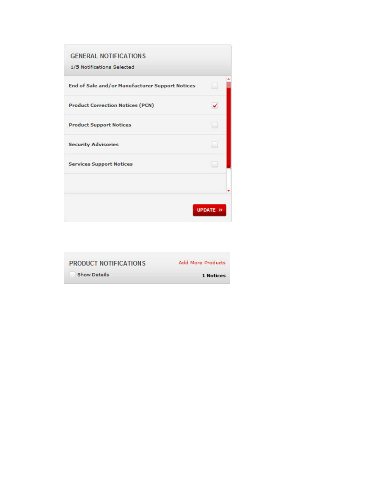
Subscribing to e-notifications
Subscribe to e-notifications to receive an email notification when documents are added to or
changed on the Avaya Support website.
About this task
You can subscribe to different types of general notifications, for example, Product Correction
Notices (PCN), which apply to any product or a specific product. You can also subscribe to specific
types of documentation for a specific product, for example, Application & Technical Notes for Virtual
Services Platform 7000.
Procedure
1. In an Internet browser, go to
2. Type your username and password, and then click Login.
3. Under My Information, select SSO login Profile.
4. Click E-NOTIFICATIONS.
5. In the GENERAL NOTIFICATIONS area, select the required documentation types, and then
click UPDATE.
https://support.avaya.com.
February 2016 Installing Avaya Ethernet Routing Switch 4900 Series 6
Comments on this document? infodev@avaya.com
Related resources
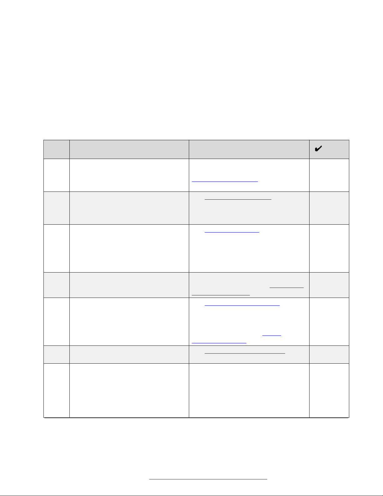
6. Click OK.
7. In the PRODUCT NOTIFICATIONS area, click Add More Products.
8. Scroll through the list, and then select the product name.
9. Select a release version.
10. Select the check box next to the required documentation types.
February 2016 Installing Avaya Ethernet Routing Switch 4900 Series 7
Comments on this document? infodev@avaya.com

Introduction
11. Click Submit.
Support
Go to the Avaya Support website at http://support.avaya.com for the most up-to-date
documentation, product notices, and knowledge articles. You can also search for release notes,
downloads, and resolutions to issues. Use the online service request system to create a service
request. Chat with live agents to get answers to questions, or request an agent to connect you to a
support team if an issue requires additional expertise.
February 2016 Installing Avaya Ethernet Routing Switch 4900 Series 8
Comments on this document? infodev@avaya.com

Chapter 2: New in this document
Installing Avaya Ethernet Routing Switch 4900 Series, NN47212-301 is a new document for 7.1 so
all the features are new in this release. See Release Notes for Avaya Ethernet Routing Switch 4900
and 5900 Series for a full list of features.
February 2016 Installing Avaya Ethernet Routing Switch 4900 Series 9
Comments on this document? infodev@avaya.com
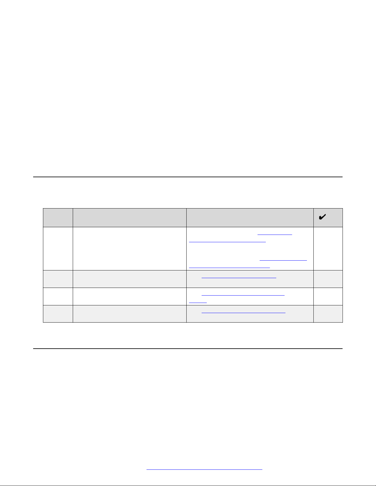
Chapter 3: Preinstallation checklist
Before you install the Ethernet Routing Switch 4900 Series, make sure that you complete the tasks
in the preinstallation checklist.
No. Task Description
1. Review the technical specification for the
switch. Make sure that the area where
you install the switch and where it will
operate meet the requirements.
2. Verify the power supply unit (PSU)
specifications. Optionally order a
redundant PSU to provide redundancy
and load sharing.
3. Make sure that you have the following
tools and cables:
• Phillips #2 screwdriver RJ-45 console
port cable
• ESD cable
4. Unpack the equipment. Observe ESD precautions when you
5. Verify the contents of the shipped
package.
6. Make sure that the power cord has the
correct country-specific termination.
7. Prepare the rack. Ensure that there is enough rack space
For the physical, electrical, and
environmental specifications, see
Technical specifications on page 16.
See AC power specifications on
page 17.
See Cable requirements on page 25.
unpack the equipment. See Electrostatic
discharge prevention on page 15.
See Verifying package contents on
page 22 for a description of the
components that are provided with the
switch. If any components are missing,
contact Avaya support at https://
support.avaya.com/.
See AC power cord specifications on
page 20.
of 1.75 inches (4.45 centimeters).
Ensure that the rack is bolted to the floor
and braced if necessary.
Ensure that the rack is grounded to the
same grounding electrode used by the
Table continues…
February 2016 Installing Avaya Ethernet Routing Switch 4900 Series 10
Comments on this document? infodev@avaya.com

No. Task Description
power service in the area. The ground
path must be permanent and must not
exceed 1 Ohm of resistance from the
rack to the grounding electrode.
See Installing the switch in an equipment
rack on page 26.
February 2016 Installing Avaya Ethernet Routing Switch 4900 Series 11
Comments on this document? infodev@avaya.com
Chapter 4: Installing Ethernet Routing
Switch 4900 Series
This chapter provides the information and procedures to install the Ethernet Routing Switch 4900
Series.
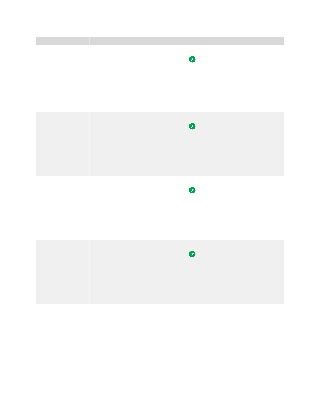
Installation checklist
Use this checklist to install the Ethernet Routing Switch 4900 Series.
No. Task Description
1. Mount the Ethernet Routing Switch
4900 Series in the equipment rack.
3. Check the LEDs to verify the
installation.
2. (Optional) Install the secondary power
supply.
4. (Optional) Connect the switches in a
stack.
To install the switch, see Installing the
Switch in an equipment rack on page 26.
To install the switch using optional four-post
rack-mount brackets, see Installing optional
four post rack mount brackets on page 30.
See Switch LED state indicators on
page 50
See Installing the secondary power
supply on page 34
See Connecting switches in a stack on
page 46
Ethernet Routing Switch 4900 Series models
This section provides information about the switches in Ethernet Routing Switch 4900 Series.
Ethernet Routing Switch 4900 Series models
The following table lists the different Ethernet Routing Switch 4900 Series models and the key
features for each switch.
February 2016 Installing Avaya Ethernet Routing Switch 4900 Series 12
Comments on this document? infodev@avaya.com
Ethernet Routing Switch 4900 Series models
Switch Model Key features Part Number
Ethernet Routing
Switch 4926GTS
• 24 ports, 10/100/1000 Base-T Ethernet
with two ports of SFP+ (10 Gbps)
interfaces
• Stackable Ethernet switch
AL4900x01-E6
Note:
Replace the “x” with a countryspecific power cord code. See the
• Non-PoE
footnote for details.
• Supports two modular 250 W Power
Supply Units (PSU), where one PSU is
required for operation and the optional
second is redundant
Ethernet Routing
Switch 4926GTSPWR+
24 ports 10/100/1000BaseT
Stackable Ethernet switch
PoE
1 rack unit high
AL4900x02-E6
Note:
Replace the “x” with a countryspecific power cord code. See the
footnote for details.
Uses modular power supply units and
has two field-serviceable power supply
receptacles, which support 250 W AC
power supply modules
Ethernet Routing
Switch 4950GTS
48 ports 10/100/1000BaseT
Stackable Ethernet switch
Non-PoE
1 rack unit high
AL4900x03-E61
Note:
Replace the “x” with a countryspecific power cord code. See the
footnote for details.
Uses modular power supply units and
has two field-serviceable power supply
receptacles, which support 1025 W AC
power supply modules
Ethernet Routing
Switch 4950GTSPWR+
48 ports 10/100/1000BaseT
Stackable Ethernet switch
PoE
1 rack unit high
AL4900x04-E6
Note:
Replace the “x” with a countryspecific power cord code. See the
footnote for details.
Uses modular power supply units and
has two field-serviceable power supply
receptacles, which support 1025 W AC
power supply modules
*Note: The character (x) in the order number indicates the power cord code. Replace the “x” with the proper
letter to indicate desired product nationalization. See the following for details:
“A”: No power cord included.
“B”: Includes European “Schuko” power cord common in Austria, Belgium, Finland, France, Germany, The
Netherlands, Norway, and Sweden.
Table continues…
February 2016 Installing Avaya Ethernet Routing Switch 4900 Series 13
Comments on this document? infodev@avaya.com

Installing Ethernet Routing Switch 4900 Series
Switch Model Key features Part Number
“C”: Includes power cord commonly used in the United Kingdom and Ireland.
“D”: Includes power cord commonly used in Japan.
“E”: Includes North American power cord.
“F”: Includes Australian power cord.
Depending on the switch model, a 250 W or 1025 W PSU and .5 m stacking cable is provided for all
switches.
Common hardware features
The following hardware features are part of all switches in ERS 4900 Series:
• Standard ERS 19 inch rack mount hole pattern allowing horizontal or vertical, flush or offset,
front or rear mount options
• Front panel:
- one serial console connection
- one USB 2.1 Type A port
- status LED display panel
The following figure illustrates ERS 4900 Series front panel.
1. 10/100/1000 Ports (LEDs above the ports)
2. USB Type-A port
3. Reset push button
4. Status LEDs
5. SFP+ ports
6. Serial console port
Figure 1: Front panel
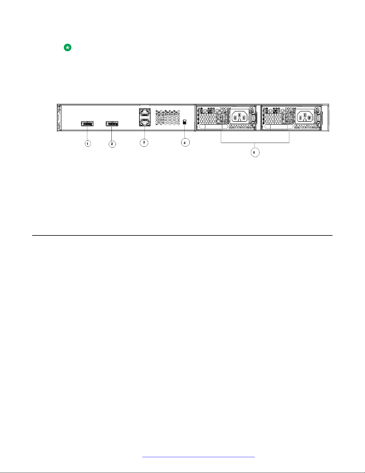
• Rear panel:
- two stack connectors
- one Base Select switch
- ports
February 2016 Installing Avaya Ethernet Routing Switch 4900 Series 14
Comments on this document? infodev@avaya.com
Electrostatic discharge prevention
Note:
The port labeled AUX is disabled.
- power supply units
- one Kensington Lock slot located on the left side, near the back end of the chassis
The following figure illustrates ERS 4900 Series rear panel.
1. Stack up connector
2. Stack down connector
3. Ports
4. Base Select Switch
5. Power Supply Units
Figure 2: Rear panel
Electrostatic discharge prevention
This module provides information and procedures for the prevention of electrostatic discharge
during the installation process.
Electrostatic discharge (ESD) is a discharge of stored static electricity that can damage equipment
and impair electrical circuitry. These electrostatic voltages can result from friction, including, but not
exclusive to, pulling cabling through conduits, walking across carpeted areas, and building up of
static charge in clothing. ESD damage occurs when electronic components are improperly handled
and can result in complete or intermittent failures. While networking equipment is commonly
designed and tested to withstand common mode ESD events, voltage sometimes can be
discharged to some connector pins but not others, or to some pins before others, which has the
potential to damage the networking equipment.
To protect the Avaya Ethernet Routing Switch against ESD damage, take the following preventive
measures before connecting any data cables to the device:
• Always use antistatic wrist straps. Make sure the strap is adjusted to provide good skin contact.
• Ensure that work surfaces and equipment racks are properly grounded for protection against
electrostatic discharge. The common point must be connected to the building ground wire. In a
properly wired building, the nearest reliable ground is typically at the electrical outlet.
• Avoid contact between equipment and clothing. The wrist or ankle strap only protects the
equipment from ESD voltages on the body; ESD voltages on clothing can still cause damage.
February 2016 Installing Avaya Ethernet Routing Switch 4900 Series 15
Comments on this document? infodev@avaya.com

Installing Ethernet Routing Switch 4900 Series
• Avoid touching any connector pins.
• Do not remove the wrist or ankle strap until the installation is complete.
With new cable installations, Avaya recommends that the use of an ESD discharge cable to reduce
the potential for damage from static that can build up in cables. See the following figure.
Figure 3: ESD cable
Technical specifications
The following table provides the technical specifications for the switches in this series. Ensure that
the area where you install the switch and where it operates meets these requirements.
Warning:
To avoid bodily injury from hazardous electrical shock and current, never remove the top of the
device. No user-serviceable components are inside.
Table 1: Physical specifications
Height 4.4 cm – 1RU
Width 17.32 inch (440 mm or 44 cm) - 19 inch rack
mountable
Depth 18.89 inch (480 mm or 48 cm)
Weight (switch weight with one PSU. Where, PSU
approximately weighs 1.6 kg)
• ERS4926GTS: 7.2 kg
• ERS4926GTS-PWR+: 7.9 kg
• ERS4950GTS: 7.3 kg
• ERS4950GTS-PWR+: 8.0 kg
February 2016 Installing Avaya Ethernet Routing Switch 4900 Series 16
Comments on this document? infodev@avaya.com
Technical specifications
Table 2: Environmental specifications
Operating Temperature 0° and 50° C (32° and 106° F)
Storage Temperature –40°C to 85°C (-40°F to 185°F)
Operating Humidity 0 to 95 percent non-condensing
Storage Humidity 0 to 95 percent non-condensing
Maximum Operating Altitude 3,048 m (10,000 feet) above sea level
Storage Altitude 0 to 12,192 m (0 to 40,000 feet) above sea level
Acoustic Noise At 25°C Ambient Temperature, less than 48 dBA
typical, at 50°C, less than 61 dBA.
Miscellaneous Operating Considerations • No nearby heat sources such as hot air vents or
direct sunlight
• No nearby sources of severe electromagnetic
noise
• No excessive dust
• Adequate power source within six feet; one circuit
required for each power supply (see table, AC
power specifications)
• At least 2 inches (5.08 cm) on each side of the
switch unit for ventilation
• Cables should be dressed to prevent blocking air
flow.
Power specifications
This section provides the following power specifications for the switch:
• AC power specifications on page 17
• Typical power consumption on page 18
• PoE+ specifications on page 19
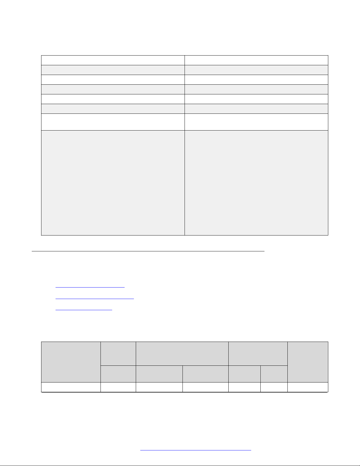
The following table describes the AC power specifications.
Table 3: AC power specifications
Model Number of
Power
supplies
Rated Line voltage Watts
ERS 4950GTS 1 250 W 200–240 VAC 53.14 0.30 181.31
Power supply Input power
(margined by 10%)
Amps
(Total)
Thermal
rating
(BTUs/hr
maximum)
Table continues…
February 2016 Installing Avaya Ethernet Routing Switch 4900 Series 17
Comments on this document? infodev@avaya.com
Installing Ethernet Routing Switch 4900 Series
Model Number of
Power
supplies
Rated Line voltage Watts
2 250 W/PSU 200–240 VAC 58.88 0.44 200.89
1 250 W 100–110 VAC 53.67 0.51 183.12
2 250 W/PSU 100–110 VAC 59.53 0.58 203.11
ERS 4926GTS 1 250 W 200–240 VAC 39.37 0.25 134.33
2 250 W/PSU 200–240 VAC 46.23 0.40 157.73
1 250 W 100–110 VAC 39.43 0.38 134.53
2 250 W/PSU 100–110 VAC 44.35 0.46 151.32
ERS 4950GTSPWR+
ERS 4926GTSPWR+
1 1025 W 200–240 VAC 820.89 3.80 358.90
2 1025 W 200–240 VAC 1586.25 7.15 584.30
1 1025 W 100–110 VAC 842.10 7.75 431.95
2 1025 W 100–110 VAC 1660.07 15.15 837.88
1 1025 W 200–240 VAC 792.53 3.57 308.88
2 1025 W 200–240 VAC 816.03 3.78 342.32
1 1025 W 100–110 VAC 825.11 7.55 413.56
2 1025 W 100–110 VAC 839.64 7.73 424.24
Power supply Input power
(margined by 10%)
Amps
(Total)
Thermal
rating
(BTUs/hr
maximum)
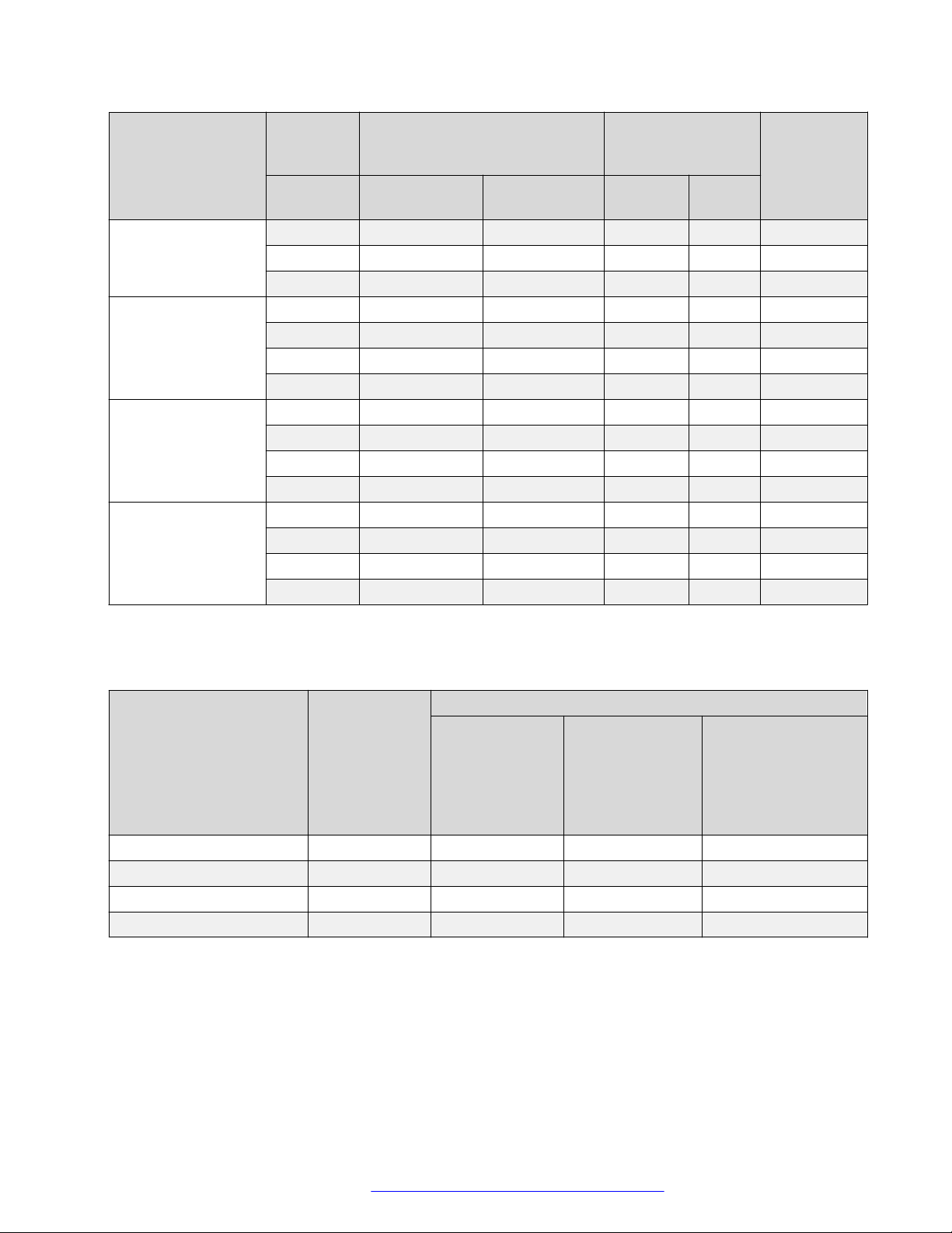
The following table provides typical power consumption.
Table 4: Typical power consumption
Model Idle Power
consumption
(Watts)
ERS 4950GTS 43.9 53.0 NA 44.0
ERS 4926GTS 34.9 40.0 NA 34.9
ERS 4950GTS-PWR+ 65.9 73.4 382.0 65.9
ERS 4926GTS-PWR+ 51.4 55.8 208.8 51.5
Devices
connected to all
ports, typical
traffic, without
SFPs
Typical Power consumption (Watts)
Devices
connected to all
ports, typical
traffic, 6 W
average per PoE
device
With Avaya Energy
Saver enabled (PoE
Saver disabled on
PoE models)
The following table describes the Power over Ethernet (PoE+) specifications.
February 2016 Installing Avaya Ethernet Routing Switch 4900 Series 18
Comments on this document? infodev@avaya.com
Loading...