


E4440A
Table of contents
 Loading...
Getting Started Guide
PSA Series Spectrum Analyzers
This manual provides documentation for the following instruments:
E4440A (3 Hz - 26.5 GHz)
E4443A (3 Hz - 6.7 GHz)
E4445A (3 Hz - 13.2 GHz)
E4446A (3 Hz - 44 GHz)
E4447A (3 Hz - 42.98 GHz)
E4448A (3 Hz - 50 GHz)
Manufacturing Part Number: E4440-90284
Supersedes: E4440-90274
Printed in USA
March 2006
© Copyright 2001-2006 Agilent Technologies, Inc.

Notice
The information contained in this document is subject to change
without notice.
Agilent Technologies makes no warranty of any kind with regard to this
material, including but not limited to, the implied warranties of
merchantability and fitness for a particular purpose. Agilent
Technologies shall not be liable for errors contained herein or for
incidental or consequential damages in connection with the furnishing,
performance, or use of this material.
The following safety symbols are used throughout this manual.
Familiarize yourself with the symbols and their meaning before
operating this analyzer.
WAR NING Warning denotes a hazard. It calls attention to a procedure
which, if not correctly performed or adhered to, could result in
injury or loss of life. Do not proceed beyond a warning note
until the indicated conditions are fully understood and met.
CAUTION Caution denotes a hazard. It calls attention to a procedure that, if not
correctly performed or adhered to, could result in damage to or
destruction of the analyzer. Do not proceed beyond a caution sign until
the indicated conditions are fully understood and met.
NOTE Note calls out special information for the user’s attention. It provides
operational information or additional instructions of which the user
should be aware.
Additional Information
For the latest information about this analyzer, including firmware
upgrades, application information, and product information, see the
following URL:
http://www.agilent.com/find/psa/
2

Contents
1. Installation and Setup
Initial Inspection . . . . . . . . . . . . . . . . . . . . . . . . . . . . . . . . . . . . . . . . . . . . . . . . . . . . . . . . . . . . . 7
Power Requirements . . . . . . . . . . . . . . . . . . . . . . . . . . . . . . . . . . . . . . . . . . . . . . . . . . . . . . . . . . 9
Turning on the Analyzer for the First Time . . . . . . . . . . . . . . . . . . . . . . . . . . . . . . . . . . . . . . . 13
Firmware Revision . . . . . . . . . . . . . . . . . . . . . . . . . . . . . . . . . . . . . . . . . . . . . . . . . . . . . . . . . . . 16
Running Internal Alignments . . . . . . . . . . . . . . . . . . . . . . . . . . . . . . . . . . . . . . . . . . . . . . . . . . 17
Printer Setup and Operation . . . . . . . . . . . . . . . . . . . . . . . . . . . . . . . . . . . . . . . . . . . . . . . . . . . 18
Protecting Against Electrostatic Discharge . . . . . . . . . . . . . . . . . . . . . . . . . . . . . . . . . . . . . . . 21
Safety Information . . . . . . . . . . . . . . . . . . . . . . . . . . . . . . . . . . . . . . . . . . . . . . . . . . . . . . . . . . . 22
2. Front and Rear Panel Features
Front Panel Overview . . . . . . . . . . . . . . . . . . . . . . . . . . . . . . . . . . . . . . . . . . . . . . . . . . . . . . . . 24
Rear-Panel Features . . . . . . . . . . . . . . . . . . . . . . . . . . . . . . . . . . . . . . . . . . . . . . . . . . . . . . . . . 29
Key Overview . . . . . . . . . . . . . . . . . . . . . . . . . . . . . . . . . . . . . . . . . . . . . . . . . . . . . . . . . . . . . . . 31
Front and Rear Panel Symbols . . . . . . . . . . . . . . . . . . . . . . . . . . . . . . . . . . . . . . . . . . . . . . . . . 33
Table of Contents
3. Making a Basic Measurement
Using the Front Panel . . . . . . . . . . . . . . . . . . . . . . . . . . . . . . . . . . . . . . . . . . . . . . . . . . . . . . . . 37
Presetting the Spectrum Analyzer . . . . . . . . . . . . . . . . . . . . . . . . . . . . . . . . . . . . . . . . . . . . . . 39
Viewing a Signal. . . . . . . . . . . . . . . . . . . . . . . . . . . . . . . . . . . . . . . . . . . . . . . . . . . . . . . . . . . . . 40
4. Viewing Catalogs and Saving Files
File Menu Functions . . . . . . . . . . . . . . . . . . . . . . . . . . . . . . . . . . . . . . . . . . . . . . . . . . . . . . . . . 49
Saving a File . . . . . . . . . . . . . . . . . . . . . . . . . . . . . . . . . . . . . . . . . . . . . . . . . . . . . . . . . . . . . . . . 53
Using the Alpha Editor . . . . . . . . . . . . . . . . . . . . . . . . . . . . . . . . . . . . . . . . . . . . . . . . . . . . . . . 62
5. Options and Accessories
Ordering Options and Accessories. . . . . . . . . . . . . . . . . . . . . . . . . . . . . . . . . . . . . . . . . . . . . . . 64
Options . . . . . . . . . . . . . . . . . . . . . . . . . . . . . . . . . . . . . . . . . . . . . . . . . . . . . . . . . . . . . . . . . . . . 65
Accessories . . . . . . . . . . . . . . . . . . . . . . . . . . . . . . . . . . . . . . . . . . . . . . . . . . . . . . . . . . . . . . . . . 71
6. In Case of Difficulty
Types of Spectrum Analyzer Messages . . . . . . . . . . . . . . . . . . . . . . . . . . . . . . . . . . . . . . . . . . . 77
Before Calling Agilent Technologies . . . . . . . . . . . . . . . . . . . . . . . . . . . . . . . . . . . . . . . . . . . . . 78
Returning an Analyzer for Service . . . . . . . . . . . . . . . . . . . . . . . . . . . . . . . . . . . . . . . . . . . . . . 81
3

Contents
Table of Contents
4

Installation and Setup
1 Installation and Setup
5
Installation and Setup
This chapter provides the following information that you may need
when you first receive your spectrum analyzer:
• “Initial Inspection” on page 7
• “Power Requirements” on page 9
• “Turning on the Analyzer for the First Time” on page 13
• “Printer Setup and Operation” on page 18
• “Protecting Against Electrostatic Discharge” on page 21
• “Running Internal Alignments” on page 17
• “Safety Information” on page 22
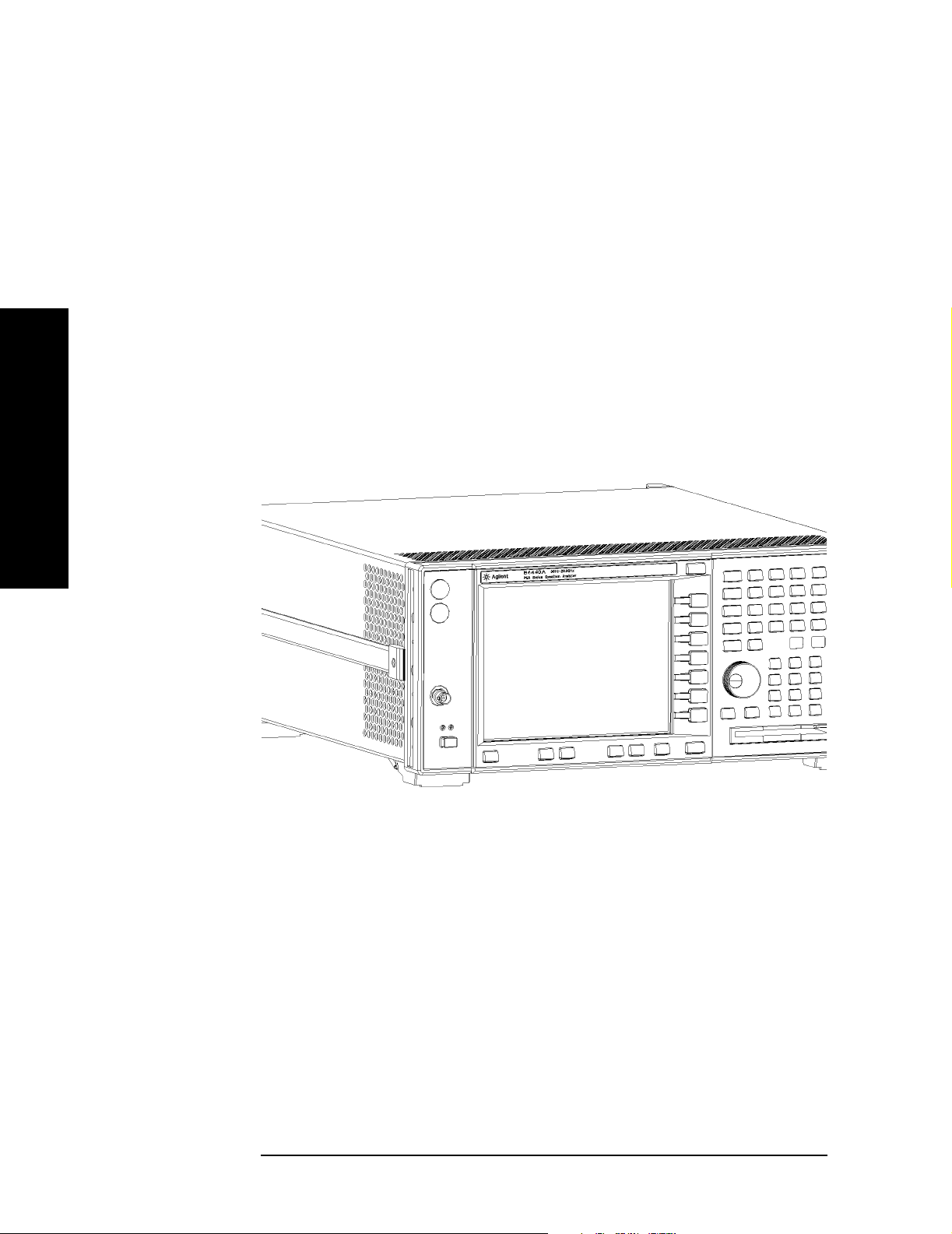
Agilent
Technologies
Performance
Installation and Setup
Spectrum
Analyzer (PSA)
6 Chapter 1
Installation and Setup
Initial Inspection
Initial Inspection
Inspect the shipping container and the cushioning material for signs of
stress. Retain the shipping materials for future use, as you may wish to
ship the analyzer to another location or to Agilent Technologies for
service. Verify that the contents of the shipping container are complete.
The following table lists the items shipped with the analyzer.
Item Description
Accessories
IntuiLink Toolbar software, CD-ROM Provides a set of connectivity tools that enable you to easily
move data from your analyzer to your PC.
Power Cable (See Table 1-2 on page 11) Connection for power source
USB Cable (Option 111 only) Connects PSA USB to USB on a PC, part number 8121-1074
Adapter (E4446A, E4447A, and E4448A
only)
Adapter (E4446A, E4447A, and E4448A
only)
Agilent Automation-Ready CD Assists in quickly and properly connecting instruments to
Standard Documentation Set
Getting Started Guide Covers unpacking and setting up the analyzer, analyzer
User’s/Programmer’s Guide Describes analyzer features in detail, including front-panel
2.4 mm(f) to K(f) front panel connector adapter, part number
1250-2187
2.4 mm(f) to 2.4 mm(f) front panel connector adapter, part
number 1250-2188
your PC, part number E2094-60003. Includes: Agilent IO
Libraries Suite, Agilent VEE Pro, T&M Tool Kit, and Agilent
IO Hardware information.
features, and how to make a basic measurement. Includes
information on options and accessories, and what to do if you
have a problem.
key descriptions, basic spectrum analyzer programming
information, and SCPI command descriptions.
Installation and Setup
Measurement Guide Provides details on how to measure various signals, and how
to use catalogs and files.
Specifications Guide Documents specifications, safety, and regulatory information.
Instrument Messages and Functional Tests Includes instrument messages (and suggestions for
troubleshooting them), and manual functional tests.
Programming Conversion Guide Describes SCPI programming command compatibility for
8590, 8560, 8566, ESA/PSA series analyzers.
Documentation CD-ROM Includes the documents in the standard set (listed above).
You can view and print the information as needed. See the
CD-ROM jacket for installation information.
Chapter 1 7

Installation and Setup
Initial Inspection
NOTE If you purchased one or more optional measurement personalities, the
related guides for the options you ordered are included.
Service documentation is not included in the standard documentation
set. See “Options” on page 65 for information on ordering.
If There Is a Problem
If the shipping materials are damaged or the contents of the container
are incomplete:
• Contact the nearest Agilent Technologies office to arrange for repair
or replacement (see “Contacting Agilent Technologies” on page 80).
You will not need to wait for a claim settlement.
• Keep the shipping materials for the carrier’s inspection.
• If you must return an analyzer to Agilent Technologies, use the
Installation and Setup
original (or comparable) shipping materials (see “Returning an
Analyzer for Service” on page 81).
8 Chapter 1

Installation and Setup
Power Requirements
Power Requirements
The only physical installation of your Agilent spectrum analyzer is a
connection to a power source.
Line voltage does not need to be selected.
This analyzer does not contain customer serviceable fuses.
WAR NING Failure to ground the analyzer properly can result in personal
injury. Before turning on the analyzer, you must connect its
protective earth terminals to the protective conductor of the
main power cable. Insert the main power cable plug into a
socket outlet that has a protective earth contact only. DO NOT
defeat the earth-grounding protection by using an extension
cable, power cable, or autotransformer without a protective
ground conductor.
Installation and Setup
If you are using an autotransformer, make sure its common
terminal is connected to the protective earth contact of the
power source outlet socket.
This is a Safety Class 1 Product (provided with a protective
earthing ground incorporated in the power cord). The mains
plug shall only be inserted in a socket outlet provided with a
protective earth contact. Any interruption of the protective
conductor inside or outside of the product is likely to make the
product dangerous. Intentional interruption is prohibited.
WAR NING To prevent electrical shock, disconnect the Agilent
Technologies spectrum analyzer from mains before cleaning.
Use a dry cloth or one slightly dampened with water to clean
the external case parts. Do not attempt to clean internally.
CAUTION VENTILATION REQUIREMENTS: When installing the product in a
cabinet, the convection into and out of the product must not be
restricted. The ambient temperature (outside the cabinet) must be less
than the maximum operating temperature of the product by 4°C for
every 100 watts dissipated in the cabinet. If the total power dissipated
in the cabinet is greater than 800 watts, then forced convection must be
used.
This analyzer has autoranging line voltage input. Be sure the supply
voltage is within the specified range.
NOTE For detailed analyzer specifications, see the Specifications guide.
Chapter 1 9
Installation and Setup
Power Requirements
Table 1-1 Power Requirements
Description
Voltage, Frequency 100 to 120 Vrms, 50/60/400 Hz
220 to 240 Vrms, 50/60 Hz
Power Consumption, On Base Fully Loaded
< 260 W < 450 W
Power Consumption, Standby < 20 W
Specification
1
1. For greater detail, refer to the Specifications Guide.
AC Power Cord
The analyzer is equipped with a three-wire power cord, in accordance
with international safety standards. This cable grounds the analyzer
cabinet when connected to an appropriate power line outlet. The cable
appropriate to the original shipping location is included with the
Installation and Setup
analyzer.
Various AC power cables are available that are unique to specific
geographic areas. You can order additional AC power cables for use in
different areas. AC Power Cords, on page 11 lists the available AC
power cables, illustrates the plug configurations, and identifies the
geographic area in which each cable is appropriate.
NOTE The front panel switch is a standby switch only; it is not a LINE switch
(power disconnecting device).
WAR NING Install the product so that the detachable power cord is readily
identifiable and easily reached by the operator. The detachable
power cord is the product disconnecting device. It disconnects
the mains circuits from the mains supply before other parts of
the product. The front panel switch is only a standby switch
and is not a LINE switch. Alternatively, an externally installed
switch or circuit breaker (which is readily identifiable and is
easily reached by the operator) may be used as a disconnecting
device.
CAUTION Always use the three-prong AC power cord supplied with this product.
Failure to ensure adequate earth grounding by not using this cord can
cause product damage.
10 Chapter 1
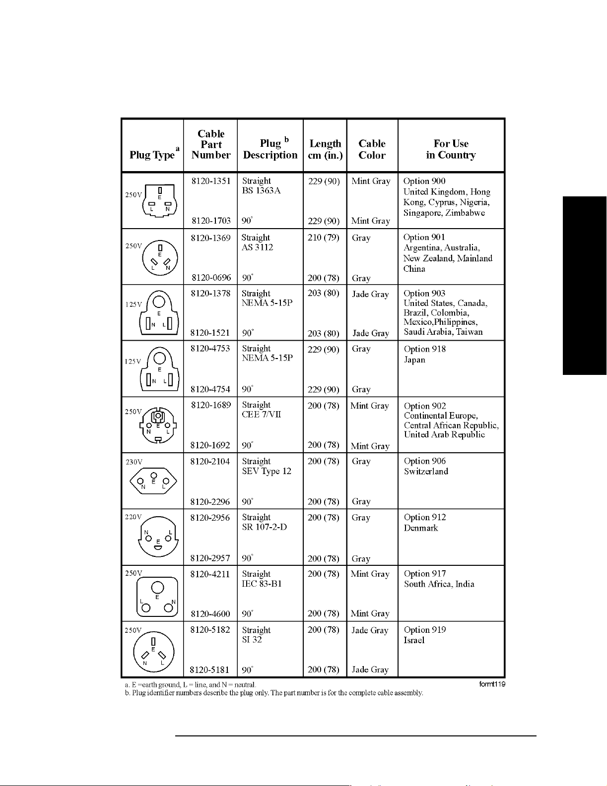
Table 1-2 AC Power Cords
Installation and Setup
Power Requirements
Installation and Setup
Chapter 1 11
Installation and Setup
Power Requirements
Battery Information
The analyzer uses a Lithium Polycarbon Monofloride battery to power
the analyzer clock. The battery is located on the CPU board.
You can order the service documentation for Agilent spectrum
analyzers through your Agilent Sales and Service office. The
documentation is described under “Options” on page 65.
NOTE If the analyzer’s clock does not keep time when powered off, the
problem is the battery. See “Returning an Analyzer for Service” on
page 81.
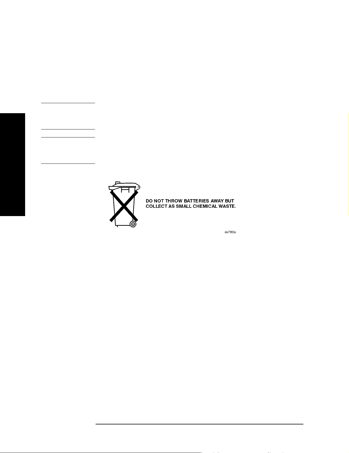
WAR NING Danger of explosion if battery is incorrectly replaced. Replace
only with the same or equivalent type recommended. Discard
used batteries according to the manufacturer’s instructions.
Installation and Setup
12 Chapter 1

Installation and Setup
Turning on the Analyzer for the First Time
Turning on the Analyzer for the First Time
❏ Plug in the power cord.
WAR NING If this product is to be energized via an external auto
transformer for voltage reduction, make sure that its common
terminal is connected to a neutral (earthed pole) of the power
supply.
CAUTION The analyzer is shipped with a a transportation disk inserted in the
disk drive to prevent damage to the disk drive during
transportation. This transportation disk, or a blank floppy disk,
should be inserted in the disk drive whenever transporting the
analyzer.
Do not leave a disk in the front-panel disk drive while turning the
analyzer on. Also, ensure that the transportation disk is removed
from the drive.
NOTE Do not connect anything else to the analyzer yet.
❏ Press the power switch (located in the lower left-hand corner of the
analyzer’s front panel) to turn the analyzer on. See “Front Panel
Overview” on page 24.
NOTE The instrument requires >2 minutes to power-on.
Information
Screen
An information screen appears during the initialization process. The
information screen contains the analyzer product number and a URL
for accessing product support information on the World Wide Web. See
“Additional Information” on page 2.
Installation and Setup
NOTE The information screen displays for approximately 10 seconds before
the initialization process is complete.
Record the firmware revision and serial number, and keep it for
reference. If you should ever need to call Agilent Technologies for
service or with any questions regarding your analyzer, it will be helpful
to have this information readily available. You can also obtain the
firmware revision and serial number by pressing
System.
Chapter 1 13
System, More, Show

Installation and Setup
Turning on the Analyzer for the First Time
❏ If using LAN, set the IP address of the analyzer to an appropriate
number for your network; one that the network recognizes, but that
is not yet in use. (Consult your local IT group):
— Press System, Config I/O, and note the IP address.
— If the current address is not appropriate, press IP Address and use
the keypad to change it.
— Connect the LAN cable to the LAN connector located on the rear
panel of your analyzer (see “Rear-Panel Features” on page 29).
— Cycle the analyzer power.
NOTE It is necessary to cycle the power to the analyzer after plugging in the
LAN for the analyzer to recognize the network.
❏ Allow the spectrum analyzer to warm-up for 30 minutes before
making a calibrated measurement. To meet its specifications, the
analyzer must meet operating temperature conditions.
Installation and Setup
NOTE It is normal to hear clicking when the Auto Alignment function is on.
See “Running Internal Alignments” on page 17 for more information.
Why Aren’t All the Personality Options Loaded in Memory?
Many measurement personality options are available for use with this
instrument. If the option is loaded in the instrument, you must also
have a license key entered, to use it.
Some versions of instrument hardware may not have enough memory
to accommodate all the options that you have ordered. If this is the case
you will need to swap the applications in/out of memory, as needed. It
may also be possible to upgrade your hardware to have more memory.
Contact your local sales/service office.
If Option 117 is Loaded in Memory
If you ordered Option 117, the Secure Memory Erase option was loaded
into the memory of your instrument and licensed at the factory but not
enabled. DO NOT enable this option until you have fully configured
your instrument (set the
removed options and licenses, and configured the power-up state you
desire). After the security mode is enabled, the main Flash memory
becomes read-only, rather than read/write memory. This makes it
impossible to add or remove personalities or their license keys, or
otherwise change the instrument’s configuration, unless you do a
System, Security, Secure Erase All procedure. This procedure will render
the instrument inoperable. You will then need to run the upgrade
System, Config I/O settings as needed, added or
14 Chapter 1

Installation and Setup
Turning on the Analyzer for the First Time
procedure (on the Agilent Web site) to reinstall the firmware and
completely reconfigure your instrument. Refer to “Managing Security”
in Chapter 4 of the “User’s and Programmer’s Reference, Volume 1.”
When you are totally satisfied with the configuration of your PSA
analyzer, enable the Secure Memory Erase option by pressing
Security, Security, Enabled
. The security mode will then be enabled the
System,
next time the analyzer’s power is cycled.
Using an External Reference
1. To use an external frequency reference, connect it to the
EXT REF IN connector on the rear panel (see “Rear-Panel
Features” on page 29).
2. Enter the frequency of the external reference into the analyzer:
a. Press System, Reference, Freq Ref
b. Select the Ext function.
c. Use the keypad to enter the frequency of the external frequency
reference.
Installation and Setup
Chapter 1 15

Installation and Setup
Firmware Revision
Firmware Revision
To view the firmware revision of your analyzer, press System, More,
Show System. If you call Agilent Technologies regarding your analyzer,
it is helpful to have this revision and the analyzer serial number
available.
TIP You can get automatic electronic notification of new firmware releases
and other product updates/information by subscribing to the Agilent
Technologies Test & Measurement E-Mail Notification Service for the
PSA and ESA Series at http://www.agilent.com/find/notifyme
Installation and Setup
16 Chapter 1

Installation and Setup
Running Internal Alignments
Running Internal Alignments
Each time the analyzer is powered on, the internal alignment routine
runs automatically.
The analyzer was shipped from the factory with the Alignments mode
set to Auto. This setting enables the alignment routine to run
automatically either every 24 hours, or when the internal analyzer
temperature changes ±3°C.
NOTE When the Alignment routine runs, you will hear the attenuator settings
changing, which generates noise. This is not an indication of trouble.
Manually Performing an Alignment
If
Auto Align, Off is selected, refer to the Specifications guide for the
conditions required to maintain calibration.
NOTE For detailed information regarding the alignment routine (including
how to run alignments, and how the analyzer can alert you when
alignments are required) refer to the User’s guide for your analyzer.
Installation and Setup
Chapter 1 17
Installation and Setup
Printer Setup and Operation
Printer Setup and Operation
A printer can be connected to your analyzer if it is equipped with an
external I/O interface. Supported printers accept Hewlett-Packard
Printer Control Language Level 3 (PCL3) or 5 (PCL5). Refer to the
documentation or specifications supplied with your printer, or contact
the manufacturer to identify your printer’s language.
Equipment
• IEEE 1284 compliant printer cable.
• Supported and tested printers are listed below. Note that there are
many PCL3/5 printers that may work with your analyzer, however,
they have not been tested.
— PCL3 printers include most HP DeskJet printers.
— PCL5 printers include most HP LaserJet printers.
Installation and Setup
NOTE The following printers are not compatible with your analyzer.
• HP Deskjet 720C, 722C, 820C and 1600C
• Epson MX-80, FX-85, Stylus, and LQ-570
Printer Models Language
Type
HP DeskJet 310, 320, 350C, 400L PCL3 yes
HP DeskJet 500C, 550C, 600, 660C, 672C,
680C, 682C, 690C, 693C
HP DeskJet 840C, 850C, 870C, 890C, 895C PCL3 yes
HP DeskJet 935C, 970C, 990C PCL3 yes
HP DeskJet 1120C, 1150C PCL3 yes
HP Inkjet 2000C PCL 3 yes
HP LaserJet 4L, 4P, 4 Plus PCL3/5 no
HP LaserJet 5L, 5M, 5N, 5P, 5SI PCL3/5 no
PCL3 yes
Color
Capable
HP LaserJet 6L, 6MP, 6P PCL5 no
HP LaserJet 2100 Series, PCL3/5 no
HP LaserJet 4050N PCL3/5 yes
HP LaserJet 5000GN PCL3/5 yes
HP Professional Series 2500CM PCL3 yes
18 Chapter 1

Installation and Setup
Printer Setup and Operation
Printer Models Language
Type
HP Professional Series 2500CM PCL3 yes
Color
Capable
Installation and Setup
Chapter 1 19

Installation and Setup
Printer Setup and Operation
Interconnection and Setup
1. Turn off the printer and the analyzer.
2. Using an IEEE 1284 compliant parallel printer cable, connect the
printer to the analyzer parallel I/O interface connector on the rear
panel (see “Rear-Panel Features” on page 29).
3. Turn on the analyzer and printer.
4. On the front panel, press Print Setup, then press the Printer Setup
menu key.
5. Select the printer language and color capability appropriate for your
printer. See table above this section for a list of some compatible
printers.
Testing Printer Operation
When you have completed the printer setup for the analyzer, press the
front panel
Installation and Setup
successful, a printout of the analyzer display will be printed. If the
Print key. If the printer is ready and the printer setup was
printer is not ready, the message “Printer not responding” appears
at the bottom of the screen.
NOTE There may be some small discrepancies in the color mapping of the
analyzer display to your color printer. Due to differences in display and
printer technologies, the default display colors do not map exactly to the
printer colors. For example trace 1 is yellow on your analyzer display
while it maps to green on your printer.
20 Chapter 1

Installation and Setup
Protecting Against Electrostatic Discharge
Protecting Against Electrostatic Discharge
Electrostatic discharge (ESD) can damage or destroy electronic
components (the possibility of unseen damage caused by ESD is present
whenever components are transported, stored, or used).
Test Equipment and ESD
To help reduce ESD damage that can occur while using test equipment:
• Before connecting any coaxial cable to an analyzer connector for the
first time each day, momentarily short the center and outer
conductors of the cable together.
• Personnel should be grounded with a 1 MΩ resistor-isolated
wrist-strap before touching the center pin of any connector and
before removing any assembly from the analyzer.
• Be sure that all instruments are properly earth-grounded to prevent
build-up of static charge.
WAR NING Do not use these first three techniques when working on
circuitry with a voltage potential greater than 500 volts.
• Perform work on all components or assemblies at a static-safe
workstation.
• Keep static-generating materials at least one meter away from all
components.
• Store or transport components in static-shielding containers.
• Always handle printed circuit board assemblies by the edges. This
reduces the possibility of ESD damage to components and prevent
contamination of exposed plating.
Installation and Setup
For information on ordering static-safe accessories, see “Accessories” on
page 71.
Additional Information about ESD
For more information about ESD and how to prevent ESD damage,
contact the Electrostatic Discharge Association (http://www.esda.org).
The ESD standards developed by this agency are sanctioned by the
American National Standards Institute (ANSI).
Chapter 1 21

Installation and Setup
Safety Information
Safety Information
WAR NING This is a Safety Class 1 Product (provided with a protective
earthing ground incorporated in the power cord). The mains
plug shall be inserted only in a socket outlet provided with a
protective earth contact. Any interruption of the protective
conductor inside or outside of the product is likely to make the
product dangerous. Intentional interruption is prohibited.
If this product is not used as specified, the protection provided
by the equipment could be impaired. This product must be used
in a normal condition (in which all means for protection are
intact) only.
Installation and Setup
22 Chapter 1

2 Front and Rear Panel Features
This chapter gives you an overview of the front and rear panels of your
analyzer. For details on analyzer keys and remote programming, refer
to the User’s and Programmer’s Reference. For connector specifications
(including input/output levels), see the Specifications guide.
Front and Rear Panel Features
23
Front and Rear Panel Features
Front Panel Overview
Front Panel Overview
This section provides information on the analyzer’s front panel,
including:
• Front Panel Connectors and Keys, see below
• “Display Annotations” on page 26
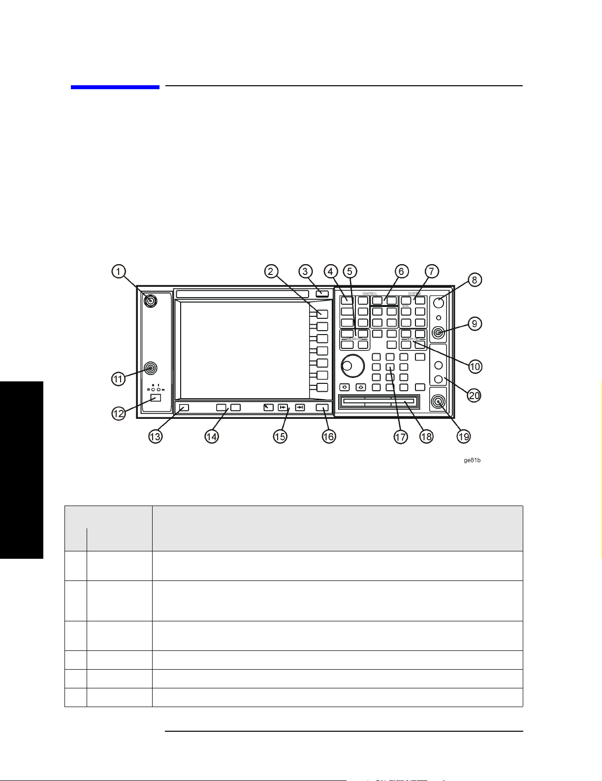
Front-Panel Connectors and Keys
Item
Description
Front and Rear Panel Features
# Name
1
AUDIO I NPU T High-impedance input for audio signal path (Option 107). Maximum input: 7 Vrms,
20 Vdc
Softkeys Menu labels identifying the current function of each softkey appear to the left of each
2
key. Softkey menus dependent on the active menu. Also see “Using Menu Keys” on page
37.
ESC Key Exits any function without modifying the current parameters. Also blanks the active
3
function annotation and aborts the power-on alignments.
4
Control Keys Set parameters used for making measurements in the current measurement mode.
5
Measure Keys Select and set up specific measurements within the current application.
Mode Keys Select measurement mode and mode parameters.
6
24 Chapter 2
Front and Rear Panel Features
Front Panel Overview
Item
Description
# Name
7 System Keys Access features used with all analyzer modes and affect the state of the entire spectrum
analyzer.
8 Vol. Control/
Earphones
9
PROBE PWR Supplies power for external high frequency probes and accessories (see “Accessories” on
Not currently implemented.
page 71).
10
Marker Keys Enable markers to obtain specific information about the displayed measurement.
EXT TRIGGER
11
INPUT
12
POWER
ON/OFF
Enables you to externally trigger measurements.
Turns the analyzer on. A green light indicates power on. A yellow light indicates
standby mode.
NOTE The front-panel switch is a standby switch, not a LINE switch
(disconnecting device); the analyzer continues to draw power
even when the line switch is in standby. Use the detachable
power cord to disconnect the analyzer from the mains supply.
Help Key Press the Help key, then any other key to get a short description of that key and the
13
associated SCPI command. The next key you press will remove the help window from
the display.
Window Keys Next Window: On displays with multiple windows, changes the highlighted window that
14
is currently active.
Zoom: Zooms in on the highlighted window.
Front and Rear Panel Features
15
Navigation
Keys
16
Return Key Exits the current menu and returns to the previous menu.
Data Controls Change the numeric value of an active function. Entries appear in the active function
17
Move cursor between fields on the display.
area of the display. Also see “Entering Data” on page 37.
Floppy
18
Disk Drive
19
RF Input Input for an external signal. Make sure that the total power of all signals at the
Accepts a 3.5 inch 1.44 MB floppy disk.
analyzer input does not exceed +30 dBm (1 watt). The E4446A, E4447A, and E4448A
input connector is 2.4 mm.
20 IF Input, 1st
LO Output
Allows connections for external mixing (Option AYZ)
Chapter 2 25
Front and Rear Panel Features
Front Panel Overview
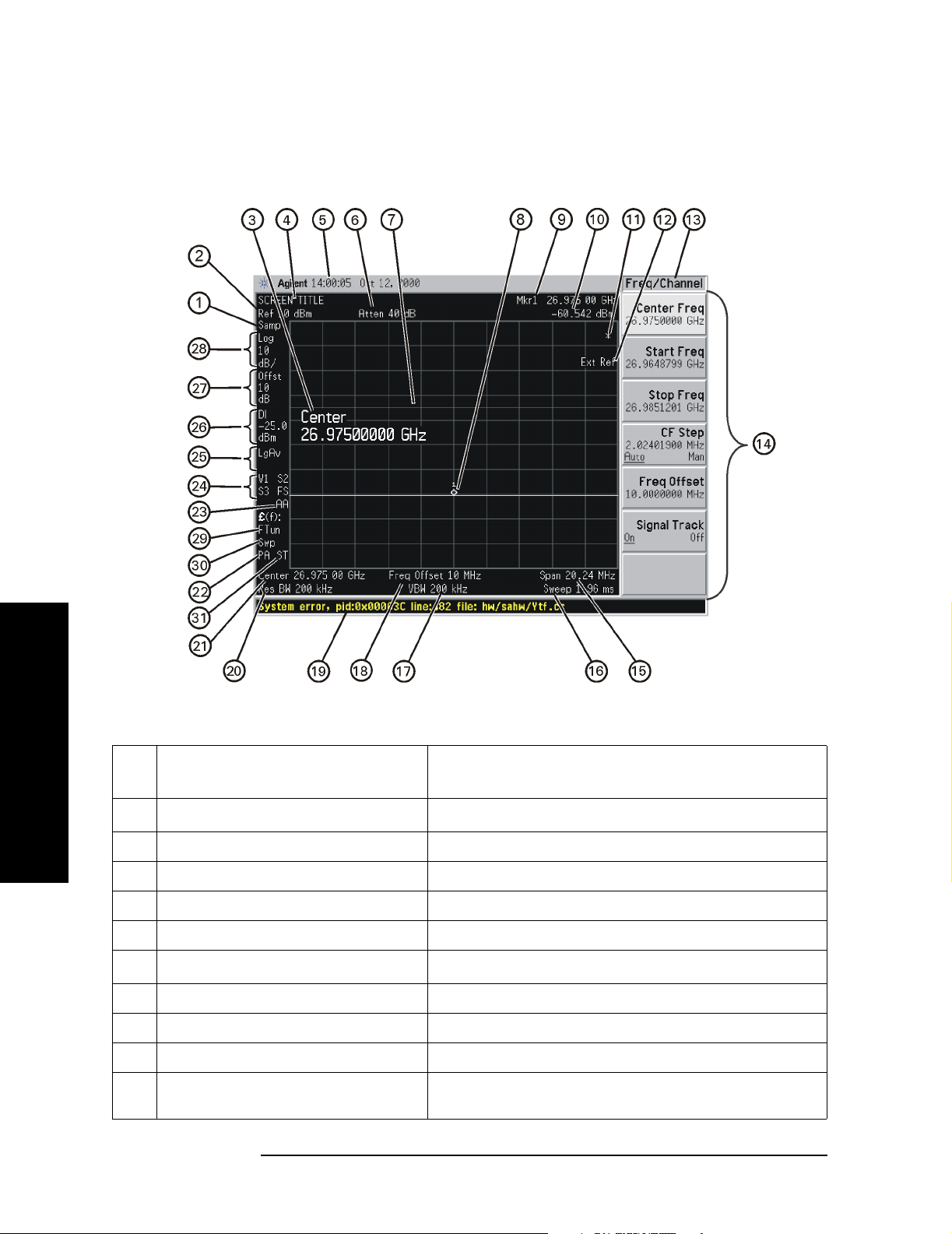
Display Annotations
Ite
m
1
Detector type
Front and Rear Panel Features
2 Reference level Amplitude, Ref Level
3 Active function block Refer to the description of the activated function.
4 Screen title
5 Time and date display System, Time/Date
6
RF attenuation
7 Display line Display, Display Line
8Marker Marker
9 Active marker Marker
10 Active marker frequency and
amplitude
Description Associated Function Keys
1
a
Det/Demod, Detector
Display, Title
Amplitude, Attenuation
Marker
26 Chapter 2
Loading...