


 Loading...
Agilent 355 Sulfur and 255 Nitrogen
Chemiluminescence Detectors
Operation and Maintenance
Manual


 Agilent Technologies

Notices
© Agilent Technologies, Inc. 2007
No part of this manual may be reproduced in any form or by any means (including electronic storage and retrieval or translation into a foreign language) without prior agreement and written consent from Agilent Technologies, Inc. as governed by United States and international copyright laws.
Acknowledgements
Torx® is a registered trademark of Textron Inc.; Teflon® is a registered trademark of E.I. du Pont de Nemours and Company. Kimwipe® is a registered trademark of the Kimberly-Clark Corporation.
Manual Part Number
G6600-90006
Edition
First edition, June 2007
Replaces G6600-90002
Printed in USA
Agilent Technologies, Inc.
2850 Centerville Road
Wilmington, DE 19808-1610 USA
Warranty
The material contained in this document is provided “as is,” and is subject to being changed, without notice, in future editions. Further, to the maximum extent permitted by applicable law, Agilent disclaims all warranties, either express or implied, with regard to this manual and any information contained herein, including but not limited to the implied warranties of merchantability and fitness for a particular purpose. Agilent shall not be liable for errors or for incidental or consequential damages in connection with the furnishing, use, or performance of this document or of any information contained herein. Should Agilent and the user have a separate written agreement with warranty terms covering the material in this document that conflict with these terms, the warranty terms in the separate agreement shall control.
Technology Licenses
The hardware and/or software described in this document are furnished under a license and may be used or copied only in accordance with the terms of such license.
Restricted Rights Legend
If software is for use in the performance of a U.S. Government prime contract or subcontract, Software is delivered and licensed as “Commercial computer software” as defined in DFAR 252.227-7014 (June 1995), or as a “commercial item” as
defined in FAR 2.101(a) or as “Restricted computer software” as defined in FAR 52.227-19 (June 1987) or any equivalent agency regulation or contract clause. Use, duplication or disclosure of Software is subject to Agilent Technologies’ standard commercial license terms, and non-DOD Departments and Agencies of the U.S. Government will receive no greater than Restricted Rights as defined in FAR 52.227-19(c)(1-2) (June 1987). U.S. Government users will receive no greater than Limited Rights as defined in FAR 52.227-14 (June 1987) or DFAR 252.227-7015 (b)(2) (November 1995), as applicable in any technical data.
Safety Notices
CAUTION
A CAUTION notice denotes a hazard. It calls attention to an operating procedure, practice, or the like that, if not correctly performed or adhered to, could result in damage to the product or loss of important data. Do not proceed beyond a CAUTION notice until the indicated conditions are fully understood and met.
WARNING
A WARNING notice denotes a hazard. It calls attention to an operating procedure, practice, or the like that, if not correctly performed or adhered to, could result in personal injury or death. Do not proceed beyond a WARNING notice until the indicated conditions are fully understood and met.
Warnings
English
WA RN ING |
This symbol on the instrument indicates that the user should refer to the man- |
|
ual for operating instructions. |
||
|
||
|
|
WA RN ING |
Any operation requiring access to the inside of the equipment, could result in |
|
injury. To avoid potentially dangerous shock, disconnect from power supply |
||
|
||
|
before opening the equipment. |
|
|
|
WA RN ING |
For continued protection against fire hazard replace fuse with same type and |
|
rating. |
||
|
||
|
|
WA RN ING |
This symbol indicates that to comply with European Union Directive |
|
2002/96/EC for waste electrical and electronic equipment (WEEE), the Ana- |
||
|
||
|
lyzer should be disposed of separately from standard waste. |
|
|
|
WA RN ING |
This is a safety Class I product. It must be wired to a mains supply with a protective |
|
earthing ground incorporated into the power cord. Any interruption of the protective |
||
|
||
|
conductor, inside or outside the equipment, is likely to make the instrument dangerous. |
|
|
Intentional interruption is prohibited. |
|
|
|
WA RN ING |
If this instrument is used in a manner not specified by Agilent, the protection provided by |
|
the instrument may be impaired. |
||
|
WA RN ING |
High voltage is present in the instrument when the power cord is connected, even if the |
|
main power switch is in the standby mode. To avoid potentially dangerous shock, discon- |
||
|
||
|
nect the power cord before removing the side panels. |
|
|
|
Operation and Maintenance Manual |
3 |
WA RN ING |
Ozone is a hazardous gas and a strong oxidant. Exposure to ozone should be minimized |
|
by using the instrument in a well-ventilated area and by venting the exhaust of the vac- |
||
|
||
|
uum pump to a fume hood. The ozone generator should be turned off when the instrument |
|
|
is not in use. |
|
|
|
WA RN ING |
Burner temperature Is extremely hot. Do not touch. Allow to cool before servicing. |
|
|
|
|
WA RN ING |
Hydrogen is an extremely flammable gas. Use appropriate care when handling. Inspect |
|
all connections with a suitable leak detector. |
||
|
||
|
|
WA RN ING |
Oxygen rich environments can promote combustion and even result in spontaneous com- |
|
bustion under conditions of high pressure and exposure to contamination. Use only oxy- |
||
|
||
|
gen rated components and ensure that components are oxygen clean prior to use with |
|
|
pure oxygen. |
|
|
|
WA RN ING |
Exceeding the gas inlet pressure of 25 psig (1.72 bar) may damage the hydrogen and oxi- |
|
dant sensors or burst their connective tubing. |
||
|
||
|
|
4 |
Operation and Maintenance Manual |

Español
WA RN ING |
Cualquier operación que requiera acceso al interior del equipo, puede causar |
|
una lesión. Para evitar peligros potenciales, desconectarlo de la alimentación |
||
|
||
|
a red antes de abrir el equipo. |
|
|
|
WA RN ING |
Para protección contínua contra el peligro de fuego, sustituir el fusible por |
|
uno del mismo tipo y características. |
||
|
||
|
|
WA RN ING |
Este símbolo en el instrumento indica que el usuario debería referirse al man- |
|
ual para instrucciones de funcionamiento. |
||
|
||
|
|
WA RN ING |
Esto es un producto con clase I de seguridad. Debe conectarse a una red que disponga de |
|
tierra protectora en el cable de red. Cualquier interrupción del conductor protector, |
||
|
||
|
dentro o fuera del equipo, puede ser peligroso. Se prohibe la interrupción intencionada. |
|
|
|
WA RN ING |
Si este instrumento se usa de una forma no especificada por Agilent, puede desactivarse |
|
la protección suministrada por el instrumento. |
||
|
Operation and Maintenance Manual |
5 |

Français
WA RN ING |
Chaque opération à l'intérieur de l'appareil, peut causer du préjudice. Afin |
|
d'éviter un shock qui pourrait être dangereux, disconnectez l'appareil du |
||
|
||
|
réseau avant de l'ouvrir. |
|
|
|
WA RN ING |
Afin de protéger l'appareil continuellement contre l'incendie, échangez le fus- |
|
ible par un fusible du même type et valeur. |
||
|
||
|
|
WA RN ING |
Le symbol indique que l'utilisateur doit consulter le manuel d'instructions. |
|
|
|
|
WA RN ING |
Ceci est un produit de Classe de sécurité I. L'instrument doit être branché sur |
|
l'alimentation secteur par un fil de secteur prévu d'une prise de masse. Chaque |
||
|
||
|
interruption du conducteur protégeant, à l'intérieur ou á l'extérieur de l'appareil peut |
|
|
rendre l'instrument dangereux. Interruption intentionnelle est interdite. |
|
|
|
WA RN ING |
Si l'instrument n'est pas utilisé suivant les instructions de Agilent, les dispositions de |
|
sécurité de l'appareil ne sont plus valables. |
||
|
6 |
Operation and Maintenance Manual |

Deutsch
WA RN ING |
Vor dem Öffnen des Gerätes Netzstecker ziehen! |
|
|
|
|
WA RN ING |
Für kontinuierlichen Schutz gegen Brandgefahr dürfen bei Sicherungswech- |
|
sel nur Sicherungen der gleichen Stärke verwendet werden! |
||
|
||
|
|
WA RN ING |
Dieses Symbol auf dem Gerät weist darauf hin, dass der Anwender zuerst das |
|
entsprechende Kapitel in der Bedienungsanleitung lesen sollte. |
||
|
||
|
|
WA RN ING |
Dies ist ein Gerät der Sicherheitsklasse I und darf nur mit einem Netzkabel mit |
|
Schutzleiter betrieben werden. Jede Unterbrechung des Schutzleiters au erhalb oder |
||
|
||
|
innerhalb des Gerätes kann das Gerät elektrisch gefährlich machen. Absichtliches |
|
|
Unterbrechen des Schutzleiters ist ausdrücklich verboten. |
|
|
|
WA RN ING |
Wenn das Gerät nicht wie durch die Firma Agilent, vorgeschrieben und im Handbuch |
|
beschrieben betrieben wird, können die im Gerät eingebauten Schutzvorrichtungen |
||
|
||
|
beeinträchtigt werden. |
|
|
|
Operation and Maintenance Manual |
7 |

Italiano
WA RN ING |
Qualsiasi intervento debba essere effettuato sullo strumento può essere |
|
potenzialmente pericoloso a causa della corrente elettrica. Il cavo di alimen- |
||
|
||
|
tazione deve essere staccato dallo strumento prima della sua apertura. |
|
|
|
WA RN ING |
Per la protezione da rischi da incendio in seguito a corto circuito, sostituire I |
|
fusibili di protezione con quelli dello stesso tipo e caratteristiche. |
||
|
||
|
|
WA RN ING |
Il simbolo sullo strumento avverte l'utilizzatore di consultare il Manuale di |
|
Istruzioni alla sezione specifica. |
||
|
||
|
|
WA RN ING |
Questo strumento è conforme alle specifiche per I prodotti in Classe I - Il cavo di |
|
alimentazione dalla rete deve essere munito di "terra". Qualsiasi interruzione del cavo di |
||
|
||
|
terra all'interno ed all'esterno dello strumento potrebbe risultare pericolòsa. Sono |
|
|
proibite interruzioni intenzionali. |
|
|
|
WA RN ING |
Se questo strumento viene utilizzato in maniera non conforme alle specifiche di Agilent, |
|
le protezioni di cui esso è dotato potrebbero essere alterate. |
||
|
8 |
Operation and Maintenance Manual |

Dutch
WA RN ING |
Iedere handeling binnenin het toestel kan beschadiging veroorzaken. Om ied- |
|
ere mogelijk gevaarlijke shock te vermijden moet de aansluiting met het net |
||
|
||
|
verbroken worden, vóór het openen van het toestel. |
|
|
|
WA RN ING |
Voor een continue bescherming tegen brandgevaar, vervang de zekering door |
|
een zekering van hetzelfde type en waarde. |
||
|
||
|
|
WA RN ING |
Het symbool geeft aan dat de gebruiker de instructies in de handleiding moet |
|
raadplegen. |
||
|
||
|
|
WA RN ING |
Dit is een produkt van veiligheidsklasse I. Het toestel moet aangesloten worden op het |
|
net via een geaard netsnoer. Bij onderbreking van de beschermende geleider, aan de |
||
|
||
|
binnenzijde of aan de buitenzijde van het toestel, kan gebruik het toestel gevaarlijk |
|
|
maken. Opzettelijke onderbreking is verboden. |
|
|
|
WA RN ING |
Indien het toestel niet gebruikt wordt volgens de richtlijnen van Agilent, gelden de |
|
veiligheidsvoorzieningen niet meer. |
||
|
Operation and Maintenance Manual |
9 |
The following symbols are used on the equipment:
Caution - Refer to manual for |
Caution - Risk of electrical |
Caution - Hot surface. |
operating instructions |
shock. |
|
Atención - Ver documentación |
Atención - Riesgo de sacudidas |
Atención - Superficie caliente. |
pertinente. |
eléctricas. |
|
Attention - Consultez les |
Attention - Risque de choc |
Attention - Surface brûlante. |
ocuments d'accomagnement. |
électrique. |
|
Vorsicht - Siehe beiliegende |
Vorsicht - Risiko eines |
Vorsicht - Heisse Oberfläche. |
Unterlagen. |
Elektroschocks. |
|
Pericolo - Vedi |
Pericolo - Pericolo di scosse |
Pericolo - Superficie rovente. |
documentazione allegata. |
elettriche. |
|
Voorzichtig - Raadpleeg di |
Voorzichtig - Hoge spanning, |
Voorzichtig - Heet oppervlak. |
bijehorende documentatie. |
levensgevaar. |
|
|
|
|
10 |
Operation and Maintenance Manual |
Contents
1Introduction
2System Description
Specifications 20 |
|
|
|
|
|
|
|
Technical Information — 355 SCD |
|
20 |
|
|
|||
Technical Information — 255 NCD |
20 |
|
|
||||
Physical Specifications |
21 |
|
|
|
|
|
|
Theory of Operation |
23 |
|
|
|
|
|
|
Sulfur Chemiluminescence Detector |
23 |
|
|||||
Nitrogen Chemiluminescence Detector |
23 |
|
|||||
Dual Plasma Controller |
24 |
|
|
|
|
|
|
Description of Major Components |
25 |
|
|
|
|||
Dual Plasma Burner |
25 |
|
|
|
|
|
|
Figure 1. Cross-Section of the Dual Plasma Burner for the 355 SCD |
26 |
||||||
Figure 2. Cross-Section of the Dual Plasma Burner for the 255 NCD |
27 |
||||||
Dual Plasma Controller |
27 |
|
|
|
|
|
|
Ozone Generator |
28 |
|
|
|
|
|
|
Chemiluminescence Reaction Cell and Photomultiplier Tube 28 |
|
||||||
Figure 3. 355 SCD Left Side |
29 |
|
|
|
|
||
Figure 4. 355 SCD Right Side |
30 |
|
|
|
|||
Figure 5. 255 NCD Left Side View |
|
31 |
|
|
|||
Figure 6. 255 NCD Right Side View |
32 |
|
|
||||
Pressure Transducer |
32 |
|
|
|
|
|
|
Vacuum Pump |
32 |
|
|
|
|
|
|
Chemical Trap |
33 |
|
|
|
|
|
|
Oil Coalescing Filter |
33 |
|
|
|
|
|
|
FID Adapter (Optional) |
33 |
|
|
|
|
|
|
NCD Reaction Cell 33 |
|
|
|
|
|
||
NCD Photomultiplier Tube and Cooler |
34 |
|
|||||
Figure 7. Schematic for 355 SCD |
35 |
|
|
||||
Figure 8. |
Schematic for 255 |
NCD, in Nitrogen Mode 36 |
Figure 9. |
Schematic for 255 |
NCD, in Nitrosamine Mode 37 |
Operation and Maintenance Manual |
11 |
3 Installation
Overview 40 |
|
|
|
|
|
|
|
Step 1: Selecting a Location |
41 |
|
|
|
|
|
|
Power Requirements |
41 |
|
|
|
|
|
|
Figure 10. Drawing of the Detector with Dual Plasma Burner and Controller |
42 |
||||||
Environmental Considerations |
42 |
|
|
|
|
||
Combustion Gas Requirements |
42 |
|
|
|
|
||
Step 2: Unpack and Inspect the Instrument |
45 |
|
|
||||
Required Installation Tools |
45 |
|
|
|
|
||
Step 3: Set Up the Vacuum Pump |
46 |
|
|
|
|
||
Installing the Edwards RV5 Pump Oil-Sealed Vacuum Pump 46 |
|
||||||
Figure 11. RV5 Oil-Sealed Vacuum Pump and Associated Traps (Front Side) |
49 |
||||||
Figure 12. RV5 Oil-Sealed Vacuum Pump and Associated Traps (Back Side) |
49 |
||||||
Figure 13. RV5 OilSealed Vacuum Pump and Associated Traps (Top) 50 |
|
||||||
Figure 14. RV-5 Oil-S ealed Vacuum Pump Exhaust Line 51 |
|
||||||
Installing the Welch Dry Piston Vacuum Pump |
52 |
|
|||||
Figure 15. The Welch Dry Piston Pump |
54 |
|
|
||||
Figure 16. Oil Drain Kit with Ballast Control |
54 |
|
|||||
Step 4: Connect the Power Cord |
56 |
|
|
|
|
||
Figure 17. SCD Rear Panel Diagram |
56 |
|
|
||||
Step 5: Install the Dry Compressed Air or O2 Supply 57 |
|
||||||
Step 6: Install the Signal Output Cables |
58 |
|
|
||||
Standard Cable Connection |
58 |
|
|
|
|
||
HP 3390 Series Integrator Cable Connection |
58 |
|
|||||
HP 3396 Integrator Cable Connection |
|
58 |
|
|
|||
HP 5890 GC Analog Input Board |
58 |
|
|
|
|
||
Agilent 6890 GC Analog Input Board |
|
58 |
|
|
|||
Step 7: Install the Dual Plasma Burner |
59 |
|
|
||||
Figure 18. Dimensions of GC Liner Cut-Outs |
59 |
|
|||||
Step 8: Install the Dual Plasma Controller |
|
60 |
|
|
|||
Figure 19. Dual Plasma Controller Rear Panel |
60 |
|
|||||
Step 9: Install Column Connections |
61 |
|
|
|
|
||
Capillary Columns |
61 |
|
|
|
|
|
|
Figure 20. Measuring Column Insertion |
61 |
|
|
||||
12 |
Operation and Maintenance Manual |
Packed Columns and Columns with an Outside Diameter > 0.8 mm 61
Step 10: Install the Transfer Line 62
4 Front Panel Controls and Initial Startup
Detector Front Panel Controls |
64 |
|
|
Figure 21. Front Panel Controls |
64 |
||
Power Controls |
64 |
|
|
Display Output Controls |
65 |
|
|
Signal Controls |
65 |
|
|
Dual Plasma Controller Controls |
66 |
||
Figure 22. Dual Plasma Controller Front Panel 66 |
|||
Initial Startup |
67 |
|
|
Detector Interface Setup 69 |
|
|
|
Initial Checkout |
69 |
|
|
Monitoring Oxidizer and Hydrogen Flow with the Dual Plasma Controller 70
5 Operation
Start-Up Procedure |
72 |
|
Detector Operation |
73 |
|
Detector Stability and Response 73 |
||
Column Bleed |
73 |
|
Coking 73 |
|
|
Hydrogen Poisoning |
73 |
|
Contaminated Gases |
74 |
|
Fluctuating Pressures |
74 |
|
Typical Operating Conditions |
75 |
Table 1. Typical Operating Conditions |
75 |
Detection Limits |
76 |
|
Table 2. Expected Detection Limits for Chromatographic Conditions 76 |
||
Instrument Shut-Down |
77 |
|
Daily Shutdown |
77 |
|
Complete Shutdown |
77 |
|
Special Operating Modes |
78 |
|
Using the 255 NCD in Nitrosamine Mode 78
Using the SCD in High Sensitivity Mode for Nonhydrocarbon Gaseous Samples 78
Operation and Maintenance Manual |
13 |
6 Maintenance
Pump Maintenance |
82 |
|
|
|
|
|
|
|
|
Table 3. Operating Life of Components for Edwards RV5 Vacuum Pump 82 |
|
|
|||||||
Cleaning the Detector |
83 |
|
|
|
|
|
|
|
|
Changing the Oil Mist Filter (RV5) |
84 |
|
|
|
|
|
|
||
Reaction Cell Cleaning |
85 |
|
|
|
|
|
|
|
|
Figure 23. Reaction Cell, PMT Housing and PMT Socket |
86 |
|
|
|
|||||
Figure 24. Reaction Cell |
86 |
|
|
|
|
|
|
|
|
Flow Sensor Calibration |
88 |
|
|
|
|
|
|
|
|
Detector Sensitivity |
89 |
|
|
|
|
|
|
|
|
Assembling the Dual Plasma Burner for Component Replacement with the SCD |
90 |
|
|||||||
Figure 25. Ferrule Placement on Lower Burner Tube |
90 |
|
|
|
|
||||
Figure 26. Proper Ferrule Orientation to the Large Ceramic Tube |
91 |
|
|
||||||
Figure 27. Large Ceramic Tube Properly Inserted into the Quartz Heater Assembly |
91 |
||||||||
Figure 28. Orientation of the Double Taper Ferrule |
92 |
|
|
|
|
||||
Figure 29. Positioning the Upper Tube in the Union Fitting |
92 |
|
|
|
|||||
Figure 30. Tightening the Heater Swivel Nut |
93 |
|
|
|
|
|
|||
Figure 31. Proper Alignment of the Burner |
93 |
|
|
|
|
|
|||
Assembling the Dual Plasma Burner for Component Replacement with the NCD |
95 |
|
|||||||
Figure 32. Ferrule Placement on Lower Burner Tube |
95 |
|
|
|
|
||||
Figure 33. Proper Ferrule Orientation to the Large Quartz Tube |
96 |
|
|
||||||
Figure 34. The Quartz Tube Properly Inserted into the Quartz Heater Assembly |
96 |
||||||||
Figure 35. Burner Assembly Detail 97 |
|
|
|
|
|
|
|||
Figure 36. Burner Assembly Alignment 97 |
|
|
|
|
|
||||
Tube Replacement for the SCD |
98 |
|
|
|
|
|
|
||
Figure 37. Orientation of the Double Taper Ferrule |
98 |
|
|
|
|
||||
Figure 38. Positioning the Upper Tube in the Union Fitting |
99 |
|
|
|
|||||
Figure 39. Proper Ferrule Orientation to the Large Ceramic Tube |
99 |
|
|
||||||
Figure 40. Large Ceramic Tube Properly Inserted into the Quartz Heater Assembly |
100 |
||||||||
Figure 41. Tightening the Heater Swivel Nut |
100 |
|
|
|
|
|
|||
Figure 42. Proper Alignment of the Burner |
101 |
|
|
|
|
|
|||
Tube Replacement for the NCD |
102 |
|
|
|
|
|
|
||
Figure 43. Proper Ferrule Orientation to the Large Quartz Tube |
102 |
|
|
||||||
Figure 44. Large Quartz Tube Properly Inserted into the Quartz Heater Assembly |
103 |
||||||||
Figure 45. NCD Tube Replacement Detail |
104 |
|
|
|
|
|
|||
Figure 46. NCD Tube Replacement Detail |
104 |
|
|
|
|
|
|||
14 |
Operation and Maintenance Manual |
7 Troubleshooting
Solving Detector Problems 106
Power Problems |
107 |
Detector Fuse |
107 |
Vacuum Pump Fuse 107
Dual Plasma Controller Fuses 107
Table 4. Fuses for 100 V, 120 V and 230 V Versions of 355 SCD and 255 NCD 108 Figure 47. Fuse Positions on the Power Supply Board 108
Ozone Generation Problems |
109 |
|
|
Ozone Generator |
109 |
|
|
High Voltage Transformer |
109 |
|
|
Plugged Restrictor Lines |
110 |
|
|
Response Problems |
111 |
|
|
Temperature Reading Problems 112 |
|
||
Diagnosing General Problems |
113 |
|
|
Table 5. Troubleshooting Detector Issues |
113 |
||
Table 6. Troubleshooting Pump Issues |
115 |
||
Table 7. Troubleshooting Burner Issues |
116 |
||
Index
Operation and Maintenance Manual |
15 |
16 |
Operation and Maintenance Manual |

Agilent 355 Sulfur and 255 Nitrogen Chemiluminescence Detectors
Operation and Maintenance Manual
1 Introduction
This manual will guide you in the installation, operation, and troubleshooting of the Agilent 355 Sulfur Chemiluminescence Detector (SCD) and the Agilent 255 Nitrogen Chemiluminescence Detector (NCD). This manual is intended for use with the Agilent 355 SCD or 255 NCD with the Dual Plasma Burner and Controller.
This operation and service manual has some important conventions, such as the use of boxed warnings. This information is deliberately set out from the text for emphasis and should be followed to assure operator safety and proper instrumental operation.
If you are installing the 355 SCD or 255 NCD yourself, follow the installation procedures described in the following sections. If your instrument is already installed, turn to the Operation section to begin.
Agilent Technologies |
17 |
18 |
Operation and Maintenance Manual |

Agilent 355 Sulfur and 255 Nitrogen Chemiluminescence Detectors Operation and Maintenance Manual
2
System Description
Specifications 20
Theory of Operation 23
Description of Major Components 25
Agilent Technologies |
19 |
Specifications
Technical Information — 355 SCD
Sensitivity*
Typical Selectivity
Linearity
Precision and Stability†
Ozone flow through the Post Ozone Restrictor Typical reaction cell pressure
Typical Burner Pressure
Typical Burner Temperature
Typical Air Flow Rate
Typical Hydrogen Flow Rate
Signal Output Ranges
Typical time to reach 800 °C from room temperature
Typical safety shroud outside temperature Recorder output
Typical < 0.5 pg S/second (signal to noise 3.3:1) g S/g C > 2 x 10⁷
>104
<2% RSD 2 hours <5% RSD 72 hours
20-30 mL/min at 3-6 psig
4 - 8 Torr RV5 Oil Sealed Pump
6 - 12 Torr Dry Piston Pump
250-400 Torr operating
800 °C
65 SCCM recommended
3-10 SCCM recommended with FID adapter
40 SCCM recommended
0-1V, 0-10V
10 min typical(120 VAC, 60 Hz)
<65 °C at 800 °C Burner temperature typical 0-1 V or 0-10 V
* Burner temperature 800 °C, 80 SCCM air, and 60 SCCM hyrdrogen, test compound dimethyl sulfide in toluene.
†Based on thiopene in benzene at 1 ppm mass sulfur, 1 µL injection split 1:10, 30 m, 0.32 mm ID, 1 µm thick CP wax (n=10 for 2.5 hours; n=42 for 72 hours).
Subject to change without notice.
Technical Information — 255 NCD
Sensitivity |
<3 pg N/second (signal to noise 3:1) in both N |
|
and nitrosamine modes |
Selectivity |
g N/g C > 2 to 107 in N mode (selectivity in |
|
nitrosamine mode is matrix-dependent) |
Linearity |
>104 |
20 |
Operation and Maintenance Manual |
Repeatability* |
<1.5% RSD 8 hours (~ the same in N and |
|
nitrosamine) |
|
<2% RSD 18 hours (~3% RSD in nitrosamine |
|
mode over 21 hours) |
Gas flow through Ozone Generator |
20-30 mL/min at 3-6 psig (inlet pressure) |
Typical reaction cell pressure |
4 - 8 Torr RV5 Oil Sealed Pump |
|
6 - 12 Torr Dry Piston Pump |
Typical Burner Pressure |
130 - 150 torr operating |
Typical Burner Temperature |
900 °C |
Typical Hydrogen Flow Rate |
6-10 SCCM |
Typical Oxygen Flow Rate |
8 - 15 SCCM |
Signal Output Ranges |
0-1V, 0-10V, 0 - 10V |
*Burner temperature 950 °C, 11 SCCM oxygen, and 6 SCCM hydrogen; 25 ppm N as nitrobenzene in toluene; 0.2 µL injection on column (HP 19095-121Z), n=7 for 3 hours; n=13 for 18 hours and n=10
n-dipropylnitrosamine in toluene at 4 µg/mL, 0.2 µL injection on column (HP 19095-121Z).
Physical Specifications
Power requirements
355 SCD Detector |
115 VAC, 50/60 Hz, 1400 W |
|
100 VAC, 50/60 Hz, 1400 W |
|
220-240 VAC, 50/60 Hz, 650W |
255 NCD Detector |
115 VAC, 50/60 Hz, 1400 W |
|
100 VAC, 50/60 Hz, 1400 W |
|
220-240 VAC, 50/60 Hz, 650W |
Dual Plasma Controller |
100-120 VAC, 50/60 Hz, 200 W |
|
220-240 VAC, 50/60 Hz, 200 W |
Dimensions and weight
Detector |
Height: 16.0 in (40.6 cm) |
|
|
Width: 9.2 in (23.4 cm) |
|
|
Depth: 21.8 in (55.3 cm) |
|
|
355 |
SCD Weight: 34.0 lbs (15.0 kg) |
|
255 |
NCD Weight: 37.5 lbs (17.0 kg) |
Operation and Maintenance Manual |
21 |
Dual Plasma Controller |
Height: 5.0 in (12.7 cm) |
|
Width: 9.5 in (24.1 cm) |
|
Depth: 12.5 in (31.8 cm) |
|
Weight: 9.9 lbs (4.5 kg) |
Dual Plasma Burner |
Height: 12.3 in (31.2 cm) |
|
Diameter: 4.0 in (10.2 cm) |
|
Weight: 1.9 lbs (0.9 kg) |
Oil Sealed Vacuum Pump (RV5) |
Height: 10.3 in (26.1 cm) |
|
Width: 6.0 in (15.2 cm) |
|
Depth: 16.9 in (43.0 cm) |
|
Weight: 47.3 lbs (21.5 kg) |
or |
|
Oil Free Dry Piston Pump |
Height: 12.0 in (30 cm) |
|
Width: 9.0 in (22.9 cm) |
|
Depth: 14.0 in (35.6 cm) |
|
Weight: 29.9 lbs (13.6 kg) |
Installation Category |
II |
Pollution Degree |
2 |
Ambient Temperature |
50 - 104 °F (10-40 °C) |
Relative Humidity |
Up to 95%, noncondensing |
Normal Operating Environment |
Intended for indoor use only |
Maximum Altitude |
2,000 m (6,562 ft) |
Mains Supply Voltage |
Fluctuation not to exceed 10% of nominal |
|
voltage |
22 |
Operation and Maintenance Manual |
Theory of Operation
Sulfur Chemiluminescence Detector
The Agilent model 355 Sulfur Chemiluminescence Detector (SCD) is a sulfur-selective detector for gas chromatography. Operation of the SCD is based on the chemiluminescence (light-producing reaction) from the reaction of ozone with sulfur monoxide (SO) produced from combustion of the analyte:
Sulfur compound (analyte) → SO + H2O + other products
SO + O3 → SO2 + O2 + hη (<300–400 nm)
A vacuum pump pulls the combustion products into a reaction cell at low pressure, where excess ozone is added. Light produced from the subsequent reaction is optically filtered and detected with a blue-sensitive photomultiplier tube and the signal is amplified for display or output to a data system. Figure 1 is a pneumatic flow diagram that illustrates how the components of the system are integrated.
The Detector has an enclosed, dedicated (Dual Plasma) Burner designed to enhance production of the SO intermediate. This Dual Plasma Burner mounts in the detector port of the GC. A Dual Plasma Controller provides temperature control and gas-flow regulation to operate the Dual Plasma Burner.
The Agilent model 355 SCD provides high sensitivity (<0.5 pg S/sec), with linear and equimolar response over four orders of magnitude (per Sulfur atom) while maintaining high selectivity over common solvents. The Agilent SCD is compatible with most commercially available gas chromatographs.
Nitrogen Chemiluminescence Detector
Operation of the Agilent model 255 Nitrogen Chemiluminescence Detector is based on the chemiluminescence or light-producing reaction of ozone with nitric oxide formed from combustion. Reacting nitric oxide with ozone results in the formation of electronically excited nitrogen dioxide. The excited nitrogen dioxide emits light, a chemiluminescence reaction, in the red and infrared region of the spectrum. The light emitted is directly proportionally to the amount of nitrogen in the sample,
NO + O3 NO2 NO2 + hη (>800 nm)
The light (hη) emitted by the chemical reaction is optically filtered and detected by a photomultiplier tube. The signal from the photomultiplier tube is amplified for display or output to a data system. Organic compounds containing nitrogen react to form nitric oxide, carbon dioxide, and water.
H2/O2 |
→ NO + CO2 + H2O |
R-N + O2 --------------- |
Operation and Maintenance Manual |
23 |
Dual Plasma Controller
The Dual Plasma Controller provides all operational parameters of the Dual Plasma Burner except for the Detector base temperature. The Detector base temperature is controlled by circuitry in the GC. Parameters monitored or regulated by the Controller include Burner temperature, Burner temperature set-point, hydrogen and oxidant flow rates, and Burner pressure. The temperature set-point, actual pressure, oxidant and hydrogen flow rates are displayed by rotation of a 4-position switch. Power, valve operation, temperature within set-point range and fault conditions are indicated with LED illumination on the front display panel.
The Dual Plasma Controller incorporates several safety features. The safety circuitry detects faults such as power loss, vacuum loss, thermocouple failure, heater element failure, broken ceramic tube, or high temperature. When a fault is detected, the Fault LED illuminates and hydrogen and oxidant flow is stopped by normally-closed solenoid valves.
Dual Plasma Burner with the 355 SCD
The Dual Plasma Burner is based on the same chemistry and basic principles of earlier SCD Burner designs. A key difference, however, is the addition of a second “flame” or “plasma,” the lower is oxygen-rich and the upper is hydrogen-rich. The Burner consists of a tower assembly that contains an outer sheath for burn protection, a heating element, thermocouple, and combustion tubes. Conversion of sulfur containing compounds to SO occurs within the ceramic reaction chamber housed in the Burner assembly. Agilent also provides a Flame Ionization Detector (FID) option for the simultaneous collection of hydrocarbon and sulfur chromatograms for some GCs.
Dual Plasma Burner with the 255 NCD
Compounds eluted from the GC column are combusted in the Dual Plasma Burner first by an oxygen rich flame (plasma) followed by catalytic combustion on a Noble metal screen. For hydrocarbons, this two stage combustion technique results in complete conversion of the matrix to products, such as carbon dioxide and water, which do not chemiluminesce with ozone. Nitrogen atoms in a compound are converted into nitric oxide and potentially other nitrogen oxide species. In the second stage, the catalyst is used to convert other nitrogen oxide species to nitric oxide, resulting in a high efficiency of conversion.
24 |
Operation and Maintenance Manual |
Description of Major Components
Dual Plasma Burner
The Dual Plasma Burner consists of a tower assembly that contains an outer sheath for burn protection, a heating element, thermocouple, and combustion tubes. In the SCD, conversion of sulfur containing compounds to SO occurs within the ceramic reaction chamber housed in the Burner assembly and potentially interfering hydrocarbons are oxidized to CO2 and H2O, with air as the oxidant. In the NCD, oxygen is used as the oxidant.
A fitting is located on top of the Burner. The vacuum line from the Detector box is connected directly to the top of this fitting and H2 is input to the longer side of this fitting. The air inlet is connected to the base of the Burner.
The Burner is mounted onto the GC by a model-specific mounting kit (see www.Agilent.com/chem or contact Agilent for the most current information). The GC column is inserted into the Burner using a 1/32" knurled nut and fused silica adapter ferrule.
A cross-section illustration of the Dual Plasma Burner for the 355 SCD is shown in Figure 1 and for the 255 NCD is shown in Figure 2.
Operation and Maintenance Manual |
25 |
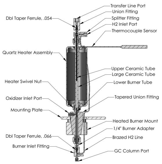
Figure 1 Cross-Section of the Dual Plasma Burner for the 355 SCD
26 |
Operation and Maintenance Manual |
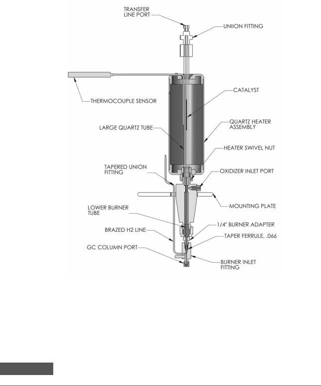
Figure 2 Cross-Section of the Dual Plasma Burner for the 255 NCD
Dual Plasma Controller
The Dual Plasma Controller powers the Dual Plasma Burner and supplies its gases. Hydrogen and oxidant should be provided at 25 psig (1.72 bar) and the Controller is plugged into an appropriate AC electrical outlet.
WA RN ING |
Exceeding the gas inlet pressure of 25 psig (1.72 bar) may damage the hydrogen and oxi- |
|
dant sensors or burst their connective tubing. |
||
|
The parameters monitored or regulated by the Controller include Burner
Operation and Maintenance Manual |
27 |
temperature, hydrogen and oxidant flow rates, and Burner pressure. The temperature, actual pressure, oxidant and hydrogen flow rates are selected for display by rotation of a 4-position control knob. Power, valve operation, temperature within set-point range and fault conditions are indicated with LED illumination on the front display panel.
The Dual Plasma Controller incorporates several safety features. The safety circuitry detects faults such as power loss, vacuum loss, thermocouple failure, heater element failure, broken ceramic tube, or high temperature. When a fault is detected, the Fault LED illuminates and hydrogen and oxidant flow is stopped by normally-closed solenoid valves.
Ozone Generator
The SCD and NCD produce ozone by corona discharge using a clean, pressurized air or oxygen source. Use of oxygen should increase ozone production and, hence, Detector response. High voltage to the ozone generator is applied only when the reaction cell pressure is less than 100 torr in the SCD and less than 200 torr in the NCD. Gas flow through the ozone generator is controlled by a pressure regulator and flow restrictors.
WA RN ING |
Ozone is a hazardous gas and a strong oxidant. Exposure to ozone should be minimized by |
|
using the instrument in a well ventilated area, changing the chemical trap regularly, and |
||
|
||
|
venting the exhaust of the vacuum pump. The ozone generator should be turned off when |
|
|
the instrument is not in use to reduce maintenance requirements. |
|
|
|
Chemiluminescence Reaction Cell and Photomultiplier Tube
Sulfur monoxide (formed in the Burner) and ozone (produced in the ozone generator located in the Detector) are mixed in the reaction cell. The cell is designed such that the reaction between SO and O3 occurs directly in front of the photomultiplier tube (PMT). A UV band pass filter (300 - 400 nm) located between the reaction cell and the PMT selectively transmits the light emitted by the SO/O3 reaction. Efficient combustion in the ceramic tubes coupled with the UV band pass filter eliminates interference from non-sulfur containing analytes (e.g. nitric oxide, olefins, etc.) which also undergo chemiluminescent reactions with ozone. A background signal is typically present as a result of ozone-wall interactions and low level sulfur contamination of Detector gases. This background signal can be used as a troubleshooting aid (see Section 10).
28 |
Operation and Maintenance Manual |
|
|
10 |
9 |
|
|
|
|
3 |
4 |
5 |
6 |
6 |
2 |
|
|
7 |
1 |
8 |
|
|
|
|
|
|
|
|
|
|
|
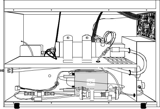
1. |
Ozone Generator |
6. |
Vacuum Line |
|
|
|
|||
2. |
High Voltage Transformer |
7. |
Particulate Filter |
|
3. |
Photomultiplier Tube Socket |
8. |
Pre-Ozone Restrictor |
|
|
|
|||
4. |
Photomultiplier Housing |
9. |
Post-Ozone Restrictor |
|
10. Pressure Transducer |
||||
5. |
Reaction Cell |
|||
|
|
|||
Figure 3 355 SCD Left Side
Operation and Maintenance Manual |
29 |

18
17
11 |
IN OFST |
OUT OFST |
|
RV1 |
RV2 |
|
I |
AMP 1 |
|
TP8 |
TP10 |
|
TP12 |
TP2 |
TP13 |
|
OUT |
|
|
|
|
|
|
TP5 |
TP4TP6 TP7 |
|
|
|
|
|
|
TP2 |
|
|
|
13 |
|
TP4 |
|
|
|
|
|
12 |
|
TP3 |
|
|
|
|
TP3 |
|
|
|
|||
|
|
|
|
|
|
ALCO |
|||
TP5 |
|
|
|
TP12 |
|
|
|
||
TP1 |
|
|
TP13 |
TP8 |
HV/100 |
TO |
|
|
|
GND |
|
|
|
TP11 |
|
|
|
||
|
|
|
|
|
|
|
FRONT |
TP1 |
|
|
|
|
TP14 |
TP9 |
|
|
PANEL |
TP9 |
|
|
|
|
|
|
|
USA |
|||
TP6 |
TP7 |
TP16 |
TP15 |
TP10 |
|
|
|
|
|
|
|
|
TP11 |
|
|||||
|
|
|
|
|
16 |
|
|
|
|
SIEVERS RESEARCH |
ELECTRONICS |
|
HV |
|
|
|
|
|
RV1 |
|
|
|
|
|
|
LOAD |
PUMP |
NEUT |
|
|
|
P4 |
P5 |
|
|
OZONE |
|
|
OUT |
WHT |
|
|
|
|
|
|
|
|
15 |
LOAD |
|
NEUT |
|
|
P6 |
OZONE |
P7 |
|
|
|
|
GEN |
WHT |
|
|
|
|
|
||
|
PUMP |
LINE |
|
NEUT |
|
|
|
|
P2 |
AC |
P3 |
|
|
|
|
|
WHT |
14
|
|
|
|
11. |
Amplifier Cable |
15. |
Fuses |
12. |
HV Cable |
16. |
Pressure Regulator |
13. |
PMT Amplifier |
17. |
Transfer line |
14. |
EMI Filter |
18. |
Front panel display |
Figure 4 355 SCD Right Side
30 |
Operation and Maintenance Manual |
Loading...