


 Loading...
S
$JLOHQW 7HFKQRORJLHV $ $WWHQXDWRU 2SHUDWLQJ DQG 3URJUDPPLQJ *XLGH
S1

Notices
continually increasing customer satisfaction through improved
Copyright © 1994-2000 Agilent |
process control. |
Technologies Deutschland GmbH. |
|
All rights reserved. |
|
No part of this manual may be |
|
reproduced in any form or by any |
|
means (including electronic |
|
storage and retrieval or translation |
|
into a foreign language) without |
|
prior agreement and written |
|
consent from Agilent Technologies, |
|
Inc. as governed by United States |
|
and international copyright laws. |
|
Warranty
The material contained in this document is subject to change without notice. Agilent Technologies makes no warranty of any kind with regard to this material, including, but not limited to, the implied warranties of merchantability and fitness for a particular purpose. Agilent Technologies shall not be liable for errors contained herein or for incidental or consequential damages in connection with the furnishing, performance, or use of this material.
Edition/Print Date
All Editions and Updates of this manual and their creation dates are listed below.
08156-91011: E0500
Second Edition ………… May 2000
First Edition W0194, E0694, E0696,
E1098
Assistance
Product maintenance agreements and other customer assistance agreements are available for Agilent Technologies products.
For any assistance, contact your nearest Agilent Technologies Sales and Service Office (see “Service and Support” on page 9).
ISO 9001 Certification
Produced to ISO 9001 international quality system standard as part of
Agilent Technologies’ objective of
Agilent Technologies GmbH
Herrenberger Str. 130
71034 Böblingen
Germany
6DIHW\ 6XPPDU\
The following general safety precautions must be observed during all phases of operation of this instrument. Failure to comply with these precautions or with specific warnings elsewhere in this manual violates safety standards of design, manufacture, and intended use of the instrument. Agilent Technologies assumes no liability for the customer’s failure to comply with these requirements.
*(1(5$/
This product is a Safety Class 1 instrument (provided with a protective earth terminal). The protective features of this product may be impaired if it is used in a manner not specified in the operation instructions.
All Light Emitting Diodes (LEDs) used in this product are Class 1 LEDs as per IEC 60825-1.
(19,5210(17$/ &21',7,216
This instrument is intended for indoor use in an installation category II, pollution degree 2 environment. It is designed to operate at a maximum relative humidity of 95% and at altitudes of up to 2000 meters. Refer to the specifications tables for the ac mains voltage requirements and ambient operating temperature range.
%()25( $33/<,1* 32:(5
Verify that the product is set to match the available line voltage, the correct fuse is installed, and all safety precautions are taken. Note the instrument’s external markings described under Safety Symbols.
*5281' 7+( ,167580(17
To minimize shock hazard, the instrument chassis and cover must be connected to an electrical protective earth ground. The instrument must be connected to the ac power mains through a grounded power cable, with the ground wire firmly connected to an electrical ground (safety ground) at the power outlet. Any interruption of the protective (grounding) conductor or disconnection of the protective earth terminal will cause a potential shock hazard that could result in personal injury.
)86(6
Only fuses with the required rated current, voltage, and specified type (normal blow, time delay, etc.) should be used. Do not use repaired fuses or short-circuited fuse holders. To do so could cause a shock or fire hazard.
'2 127 23(5$7( ,1 $1 (;3/26,9( $70263+(5(
Do not operate the instrument in the presence of flammable gases or fumes.
'2 127 5(029( 7+( ,167580(17 &29(5
Operating personnel must not remove instrument covers. Component replacement and internal adjustments must be made only by qualified service personnel.
Instruments that appear damaged or defective should be made inoperative and secured against unintended operation until they can be repaired by qualified service personnel.
2WKHU 6DIHW\ ,QIRUPDWLRQ
•Adjustments described in this manual are performed with power supplied to the instrument while protective covers are removed. Be aware that energy at many points, if contacted, result in personal injury.
•Do not install substitute parts or perform any unauthorized modification to the instrument.
•Be aware that capacitors inside the instrument may still be charged even if the instrument has been connected from its source of supply.
:$5 1,1* To avoid hazardous electrical shock, do not operate the instrument
if there are any signs of damage to any portion of the outer enclosure (covers, panels, and so on).
:$5 1,1* To avoid the possibility of injury or death, you must observe the following precautions before powering on the instrument.
–If this instrument is to be energized via an autotransformer for voltage reduction, ensure that the Common terminal connects to the earthed pole of the power source.
–Insert the power cable plug only into a socket outlet provided with a protective earth contact. Do not negate this protective action by the using an extension cord without a protective conductor.
–Before switching on the instrument, the protective earth terminal of the instrument must be connected to a protective conductor. You can do this by using the power cord supplied with the instrument.
–It is prohibited to interrupt the protective earth connection intentionally.
•The following work should be carried out by a qualified electrician. All local electrical codes must be strictly observed:
If the plug on the cable does not fit the power outlet, or if the cable is to be attached to a terminal block, cut the cable at the plug end and rewire it.
The color coding used in the cable depends on the cable supplied. If you are connecting a new plug, it should meet the local safety requirements and include the following features:
•Adequate load-carrying capacity (see table of specifications).
•Ground connection.
•Cable clamp.
:$5 1,1* To avoid the possibility of injury or death, please note that the
Agilent 8156A does not have a floating earth.
: $5 1,1* The Agilent 8156A is not designed for outdoor use. To prevent potential fire or shock hazard, do not expose the instrument to rain or other excessive moisture.
:DUQLQJV DQG &DXWLRQV
: $5 1,1* The WARNING sign denotes a hazard. It calls attention to a procedure, practice, or the like, which, if not correctly performed or adhered to, could result in personal injury. Do not proceed beyond a WARNING sign until the indicated conditions are fully understood and met.

&$ 87,2 1 The CAUTION sign denotes a hazard. It calls attention to an operating procedure, or the like, which, if not correctly performed or adhered to, could result in damage to or destruction of part or all of the product. Do not proceed beyond a CAUTION sign until the indicated conditions are fully understood and met.
6DIHW\ 6\PEROV
&DXWLRQ UHIHU WR DFFRPSDQ\LQJ GRFXPHQWV
:DUQLQJ ULVN RI HOHFWULF VKRFN
)UDPH RU FKDVVLV WHUPLQDO
3URWHFWLYH HDUWK JURXQG WHUPLQDO
+D]DUGRXV ODVHU UDGLDWLRQ
$ERXW 7KLV 0DQXDO
7KH 6WUXFWXUH RI WKLV 0DQXDO
This manual is divided into 4 parts:
•Chapter 1 tells you how to set up your Attenuator.
•Chapters 2 to 6 shows you what you can do with your Attenuator.
•Chapters 7 to 9 show you how you can remotely program your Attenuator, using GPIB commands.
•The appendices contain additional information not required for routine day-to-day use.
6HUYLFH DQG 6XSSRUW
Any adjustment, maintenance, or repair of this product must be performed by qualified personnel. Contact your customer engineer through your local Agilent Technologies Service Center. You can find a list of local service representatives on the Web at: http://www.agilent-tech.com/services/English/index.html
If you do not have access to the Internet, one of these centers can direct you to your nearest representative:
8QLWHG 6WDWHV |
7HVW DQG 0HDVXUHPHQW &DOO &HQWHU |
|
7ROO IUHH LQ 86 |
&DQDGD |
|
(XURSH |
|
-DSDQ |
0HDVXUHPHQW$VVLVWDQFH &HQWHU |
|
|
|
)$; |
/DWLQ $PHULFD |
|
|
)$; |
$XVWUDOLD 1HZ |
$XVWUDOLD |
=HDODQG |
1HZ =HDODQG |
|
|
$VLD 3DFLILF |
|
|
)$; |
Table of Contents
1 Getting Started
1.1 |
Using the Attenuator .............................................. |
29 |
|
Using the Modify Keys ...................................................... |
29 |
1.2 |
Making an Attenuation Sweep .............................. |
30 |
|
Making an Automatic Sweep ............................................ |
30 |
1.3 The Manual Sweep ................................................. |
31 |
|
1.4 |
Using your Attenuator as a Variable Back Reflector |
|
32 |
|
|
1.5 Using the Through-Power Mode .......................... |
33 |
|
1.6 Selecting the Wavelength Calibration and Its Function
33
2 Using the Attenuator |
|
|
2.1 |
Setting Up the Hardware ...................................... |
37 |
2.2 |
Setting Up the Attenuation ..................................... |
38 |
|
Entering the Attenuation Factor ........................................ |
38 |
|
Entering a Calibration Factor ............................................ |
39 |
|
Entering the Wavelength ................................................... |
40 |
2.3 |
Example, Setting the Calibration .......................... |
42 |
3 Making an Attenuation Sweep
3.1 Configuring the Hardware .................................... |
47 |
11

Table of Contents |
|
3.2 The Automatic Sweep ............................................ |
48 |
Setting Up an Automatic Sweep ........................................ |
48 |
Executing the Automatic Sweep ........................................ |
50 |
3.3 The Manual Sweep ................................................. |
51 |
Setting Up a Manual Sweep ............................................... |
51 |
Executing the Manual Sweep ............................................. |
53 |
3.4 Example, an Automatic Attenuation Sweep ......... |
54 |
4 Using your Attenuator as a Variable Back Re-
flector
4.1 |
Configuring the Hardware .................................... |
59 |
4.2 |
Setting Up the Software ......................................... |
60 |
|
Editing the Setup ................................................................. |
60 |
|
Executing the Back Reflector Application ......................... |
61 |
4.3 |
Example, Setting a Return Loss ............................ |
62 |
5 Setting Up the System
5.1 Setting the GPIB Address ..................................... |
67 |
Resetting the GPIB Address ............................................... |
67 |
5.2 Selecting the Wavelength Calibration and Its Function |
|
67 |
|
Setting the Function of the Wavelength Calibration .......... |
68 |
Selecting the Wavelength Calibration Data ....................... |
69 |
12

|
Table of Contents |
|
5.3 |
Selecting the Through-Power Mode ..................... |
70 |
|
Deselecting the Through-Power Mode ............................... |
71 |
|
Resetting the Through-Power Mode .................................. |
71 |
5.4 |
Setting the Display Brightness .............................. |
71 |
|
Resetting the Display Brightness ....................................... |
71 |
5.5 |
Selecting the Setting used at Power-On ............... |
72 |
|
Resetting the Power-On Setting ........................................ |
72 |
5.6 Locking Out ENB/DIS ............................................. |
72 |
|
|
Resetting the ENB/DIS Lock Out ....................................... |
73 |
5.7 |
Selecting the Shutter State at Power On .............. |
73 |
|
Resetting the Shutter State at Power On ............................ |
73 |
5.8 |
Setting the Display Resolution .............................. |
74 |
|
Resetting the Display Resolution ...................................... |
74 |
6 Storing and Recalling Settings |
|
6.1 Storing the Setting ................................................. |
77 |
6.2 Recalling a Setting .................................................. |
77 |
Resetting the Instrument .................................................... |
77 |
Recalling a User Setting .................................................... |
77 |
7 Programming the Attenuator
7.1 |
GPIB Interface ....................................................... |
81 |
7.2 |
Setting the GPIB Address ..................................... |
83 |
13

Table of Contents
7.3 Returning the Instrument to Local Control ........ |
83 |
7.4 How the Attenuator Receives and Transmits Messages
83
How the Input Queue Works .............................................. |
83 |
The Output Queue .............................................................. |
84 |
The Error Queue ................................................................. |
84 |
7.5 Some Notes about Programming and Syntax Diagram |
|
Conventions .................................................................. |
85 |
Short Form and Long Form ................................................ |
85 |
Command and Query Syntax ............................................. |
86 |
8 Remote Commands |
|
8.1 Units ........................................................................ |
89 |
8.2 Command Summary .............................................. |
89 |
8.3 The Common Commands ..................................... |
93 |
Common Status Information .............................................. |
93 |
*CLS ................................................................................... |
95 |
*ESE ................................................................................... |
95 |
*ESR? .................................................................................. |
96 |
*IDN? ................................................................................. |
97 |
*OPC .................................................................................. |
98 |
*OPT? ................................................................................ |
98 |
*RCL .................................................................................. |
99 |
*RST .................................................................................. |
99 |
*SAV .................................................................................. |
100 |
*SRE .................................................................................. |
101 |
*STB? ................................................................................. |
102 |
14

Table of Contents |
|
*TST? ................................................................................ |
103 |
*WAI ................................................................................. |
104 |
8.4 DISPlay Commands ................................................ |
104 |
:DISPlay:BRIGhtness ........................................................ |
104 |
:DISPlay:ENABle .............................................................. |
105 |
8.5 INPut Commands ................................................... |
106 |
:INPut:ATTenuation .......................................................... |
106 |
:INPut:LCMode ................................................................. |
107 |
:INPut:OFFSet ................................................................... |
107 |
:INPut:OFFSet:DISPlay .................................................... |
108 |
:INPut:WAVelength .......................................................... |
109 |
8.6 OUTPut Commands ............................................... |
110 |
:OUTPut:APMode ............................................................. |
110 |
:OUTPut:POWer ............................................................... |
112 |
:OUTPut:[:STATe] ............................................................ |
113 |
:OUTPut:[:STATe]:APOWeron ........................................ |
114 |
8.7 STATus Commands ............................................... |
114 |
:STATus:OPERation:CONDition? .................................... |
116 |
:STATus:OPERation:ENABle .......................................... |
117 |
:STATus:OPERation[:EVENt]? ........................................ |
117 |
:STATus:OPERation:NTRansition ................................... |
118 |
:STATus:OPERation:PTRansition .................................... |
118 |
:STATus:QUEStionable:CONDition? ............................... |
119 |
:STATus:QUEStionable:ENABle ..................................... |
119 |
:STATus:QUEStionable[:EVENt]? ................................... |
120 |
:STATus:QUEStionable:NTRansition .............................. |
120 |
:STATus:QUEStionable:PTRansition ............................... |
121 |
:STATus:PRESet ............................................................... |
122 |
8.8 SYSTem Commands ............................................... |
122 |
15

Table of Contents |
|
:SYSTem:ERRor? .............................................................. |
122 |
8.9 User Calibration Commands ................................. |
123 |
Entering the User Calibration Data .................................... |
123 |
9 Programming Examples |
|
|
9.1 Example 1 - Checking Communication ................ |
131 |
|
9.2 Example 2 |
- Status Registers and Queues ............ |
132 |
9.3 Example 3 |
- Measuring and Including the Insertion |
|
Loss ................................................................................. |
|
135 |
9.4 Example 4 |
- Running an Attenuation Sweep ........ |
139 |
A Installation |
|
|
A.1 |
Safety Considerations ........................................... |
143 |
A.2 |
Initial Inspection ................................................... |
143 |
A.3 AC Line Power Supply Requirements ................ |
144 |
|
|
Line Power Cable ............................................................... |
144 |
|
Replacing the Battery ......................................................... |
146 |
|
Replacing the Fuse ............................................................. |
146 |
A.4 |
Operating and Storage Environment ................... |
148 |
|
Temperature ........................................................................ |
148 |
|
Humidity ............................................................................ |
148 |
|
Instrument Positioning and Cooling ................................... |
148 |
A.5 |
Switching on the Attenuator ................................. |
149 |
16

|
Table of Contents |
|
A.6 Monitor Output ...................................................... |
149 |
|
A.7 |
Optical Output ...................................................... |
150 |
|
Disabling the Optical Output ............................................. |
150 |
A.8 |
GPIB Interface ...................................................... |
150 |
|
Connector ........................................................................... |
151 |
|
GPIB Logic Levels ............................................................ |
152 |
A.9 Claims and Repackaging ....................................... |
152 |
|
|
Return Shipments to Agilent Technologies ........................ |
152 |
B Accessories |
|
|
B.1 |
Instrument and Options ....................................... |
157 |
B.2 GPIB Cables and Adapters .................................. |
157 |
|
B.3 |
Connector Interfaces and Other Accessories ...... |
158 |
|
Straight Contact Connector ................................................ |
158 |
|
Option 201, Angled Contact Connector ............................. |
160 |
C Specifications |
|
|
C.1 |
Definition of Terms ............................................... |
165 |
C.2 |
Specifications .......................................................... |
167 |
|
Supplementary Performance Characteristics ...................... |
169 |
C.3 |
Other Specifications ............................................... |
171 |
C.4 |
Declaration of Conformity .................................... |
172 |
17

|
Table of Contents |
|
D Performance Tests |
|
|
D.1 Equipment Required ............................................. |
175 |
|
D.2 |
Test Record ............................................................. |
177 |
D.3 |
Test Failure ............................................................. |
177 |
D.4 |
Instrument Specification ....................................... |
177 |
D.5 |
Performance Test ................................................... |
178 |
|
I. Total Insertion Loss Test ................................................. |
179 |
|
II. Linearity/Attenuation Accuracy Test ............................. |
182 |
|
III. Attenuation Repeatability Test ...................................... |
184 |
|
IV. Return Loss Test ........................................................... |
185 |
D.6 |
V. Polarization Dependent Loss (PDL): Optional 191 |
|
|
Polarization Dependant Loss Test (Mueller method) ......... |
192 |
E Cleaning Information |
|
|
|
Cleaning Instructions for this Instrument ............................ |
248 |
E.1 |
Safety Precautions .................................................. |
249 |
E.2 |
Why is it important to clean optical devices ? ..... |
249 |
E.3 |
What do I need for proper cleaning? ................... |
250 |
|
Standard Cleaning Equipment ............................................. |
250 |
|
Additional Cleaning Equipment .......................................... |
253 |
E.4 |
Preserving Connectors ........................................... |
256 |
|
Making Connections ........................................................... |
256 |
|
Dust Caps and Shutter Caps ................................................ |
256 |
|
Immersion Oil and Other Index Matching Compounds ...... |
256 |
18

|
Table of Contents |
|
E.5 |
Cleaning Instrument Housings ............................. |
257 |
E.6 |
Which Cleaning Procedure should I use ? ........... |
257 |
|
Light dirt ............................................................................. |
257 |
|
Heavy dirt ........................................................................... |
257 |
E.7 |
How to clean connectors ........................................ |
258 |
|
Preferred Procedure ............................................................ |
258 |
|
Procedure for Stubborn Dirt ............................................... |
258 |
|
An Alternative Procedure ................................................... |
259 |
E.8 |
How to clean connector adapters .......................... |
259 |
|
Preferred Procedure ............................................................ |
259 |
|
Procedure for Stubborn Dirt ............................................... |
260 |
E.9 |
How to clean connector interfaces ........................ |
260 |
|
Preferred Procedure ............................................................ |
260 |
|
Procedure for Stubborn Dirt ............................................... |
261 |
E.10 How to clean bare fiber adapters ........................ |
261 |
|
|
Preferred Procedure ............................................................ |
261 |
|
Procedure for Stubborn Dirt ............................................... |
262 |
E.11 How to clean lenses ............................................... |
262 |
|
|
Preferred Procedure ............................................................ |
262 |
|
Procedure for Stubborn Dirt ............................................... |
263 |
E.12 How to clean instruments with a fixed connector inter- |
||
face .................................................................................. |
263 |
|
E.13 How to clean instruments with an optical glass plate 264
E.14 How to clean instruments with a physical contact in- |
|
terface ............................................................................. |
264 |
Preferred Procedure ............................................................ |
265 |
Procedure for Stubborn Dirt ............................................... |
265 |
19

Table of Contents |
|
E.15 How to clean instruments with a recessed lens inter- |
|
face .................................................................................. |
265 |
Preferred Procedure ............................................................. |
266 |
Procedure for Stubborn Dirt ................................................ |
266 |
E.16 How to clean optical devices which are sensitive to me- |
|
chanical stress and pressure ......................................... |
267 |
Preferred Procedure ............................................................. |
267 |
Procedure for Stubborn Dirt ................................................ |
267 |
Alternative Procedure .......................................................... |
267 |
E.17 How to clean metal filters or attenuator gratings 268 |
|
Preferred Procedure ............................................................. |
268 |
Procedure for Stubborn Dirt ................................................ |
268 |
E.18 Additional Cleaning Information ....................... |
268 |
How to clean bare fiber ends ............................................... |
269 |
How to clean large area lenses and mirrors ......................... |
269 |
Preferred Procedure ............................................................. |
269 |
Procedure for Stubborn Dirt ................................................ |
270 |
Alternative Procedure A ...................................................... |
270 |
Alternative Procedure B ...................................................... |
271 |
E.19 Other Cleaning Hints ........................................... |
271 |
Making the connection ........................................................ |
271 |
Lens cleaning papers ........................................................... |
271 |
Immersion oil and other index matching compounds ......... |
272 |
Cleaning the housing and the mainframe ............................ |
272 |
F Error messages
F.1 Display Messages ................................................... |
275 |
20
Table of Contents |
|
F.2 GPIB Messages ....................................................... |
276 |
Command Errors ................................................................. |
276 |
Execution Errors ................................................................. |
280 |
Device-Specific Errors ....................................................... |
281 |
Query Errors ....................................................................... |
282 |
Instrument Specific Errors .................................................. |
283 |
21

Table of Contents
22

List of Figures |
|
Figure 1-1 The Attenuator Keys ................................................................................ |
29 |
Figure 1-2 The Modify Keys ..................................................................................... |
30 |
Figure 1-3 The Parameters for an Automatic Sweep ................................................. |
31 |
Figure 1-4 The Hardware Configuration for the Back Reflector (Options 201 and 203) 32 |
|
Figure 2-1 The Hardware Configuration for the Attenuator ...................................... |
37 |
Figure 2-2 The Attenuation Factor on the Display .................................................... |
38 |
Figure 2-3 The Calibration Factor on the Display ..................................................... |
39 |
Figure 2-4 The Wavelength on the Display ............................................................... |
41 |
Figure 2-5 Hardware Configuration for Attenuation Example - A ........................... |
42 |
Figure 2-6 Hardware Configuration for Attenuation Example - B ............................ |
43 |
Figure 3-1 The Hardware Configuration for the Attenuator ...................................... |
47 |
Figure 3-2 The Parameters for an Automatic Sweep ................................................. |
49 |
Figure 3-3 Selecting the Automatic Sweep Application ........................................... |
49 |
Figure 3-4 Running the Automatic Sweep ................................................................ |
51 |
Figure 3-5 Editing the STOP Parameter .................................................................... |
52 |
Figure 3-6 Running the Manual Sweep ..................................................................... |
53 |
Figure 4-1 The Hardware Configuration for the Back Reflector ............................... |
59 |
Figure 4-2 Editing the Value for the Reference Return Loss .................................... |
61 |
Figure 4-3 Executing the Back Reflector Application ............................................... |
62 |
Figure 4-4 Hardware Configuration for Variable Return Loss .................................. |
63 |
Figure 5-1 The LAMBDCAL Indicator on the Display ................................................ |
68 |
Figure 5-2 The USERCAL Indicator on the Display .................................................. |
69 |
Figure 5-3 The Display in Through-Power Mode ..................................................... |
70 |
Figure 6-1 The Display when Recalling the Default Setting ..................................... |
77 |
Figure 8-1 Common Status Registers ........................................................................ |
94 |
Figure 8-2 The Status Registers ................................................................................. |
116 |
Figure 9-1 Hardware Configuration for Attenuation Example - A ........................... |
135 |
Figure 9-2 Hardware Configuration for Attenuation Example - B ............................ |
136 |
Figure A-1 Line Power Cables - Plug Identification ................................................. |
144 |
Figure A-2 Rear Panel Markings ............................................................................... |
145 |
Figure A-3 Releasing the Fuse Holder ...................................................................... |
147 |
Figure A-4 The Fuse Holder ...................................................................................... |
147 |
Figure A-5 Correct Positioning of the Attenuator ..................................................... |
149 |
Figure A-6 GPIB Connector ...................................................................................... |
151 |
Figure B-1 Straight Contact Connector Configuration .............................................. |
159 |
23

|
|
List of Figures |
|
Figure B-2 Angled Contact Connector Configuration .............................................. |
160 |
||
Figure D-1 Total Insertion Loss Test Setup 1, Options 100, 101, 121 ...................... |
179 |
||
Figure D-2 Total Insertion Loss Test Setup 1, Options 201, 221 .............................. |
180 |
||
Figure D-3 Total Insertion Loss Test Setup 1, Option 350 ....................................... |
180 |
||
Figure D-4 Total Insertion Loss Test Setup 2, Options 100, 101, 121 ...................... |
181 |
||
Figure D-5 Total Insertion Loss Test Setup 2, Options 201, 221 .............................. |
181 |
||
Figure D-6 |
Total Insertion Loss Test Setup 2, Option 350 ....................................... |
182 |
|
Figure D-7 |
Return Loss Test Setup 1, Options 100, 101, 121 .................................. |
185 |
|
Figure D-8 |
Return Loss Test Setup 2, Options 100, 101 .......................................... |
187 |
|
Figure D-9 |
Return Loss Test Setup 2, Option 121 .................................................... |
187 |
|
Figure D-10 Return Loss Test Setup 1, Options 201, 221 ........................................ |
188 |
||
Figure D-11 |
Return Loss Test Setup 2, Option 201 .................................................. |
189 |
|
Figure D-12 |
Return Loss Test Setup 2, Option 221 .................................................. |
190 |
|
Figure D-13 |
PDL Test Setup 1: Reference Measurement ......................................... |
192 |
|
Figure D-14 |
PDL Test Setup 2: Power after DUT .................................................... |
198 |
|
24

|
List of Tables |
|
Table 7-1 GPIB Capabilities ...................................................................................... |
82 |
|
Table 8-1 Units and Allowed Mnemonics ................................................................. |
89 |
|
Table 8-2 Common Command Summary .................................................................. |
89 |
|
Table 8-3 Command List ........................................................................................... |
90 |
|
Table 8-4 The Event Status Enable Register .............................................................. |
96 |
|
Table 8-5 The Standard Event Status Register ........................................................... |
97 |
|
Table 8-6 |
Reset State (Default Setting) ..................................................................... |
100 |
Table 8-7 |
The Service Request Enable Register ........................................................ |
101 |
Table 8-8 |
The Status Byte Register ............................................................................ |
102 |
Table 8-9 |
The Self Test Results.................................................................................. |
103 |
Table A-1 Temperature .............................................................................................. |
148 |
|
Table C-1 Specifications - Options 100, 101 and 201 ................................................ |
167 |
|
Table C-2 Monitor Output Options ........................................................................... |
168 |
|
Table C-3 Multimode Options ................................................................................... |
169 |
|
Table D-1 Equipment Required for the Agilent 8156A (1310/1550nm) ................... |
176 |
|
Table D-2 Equipment for the PDL test 1 .................................................................... |
191 |
|
Table D-3 Performance Test Agilent 8156A ............................................................. |
200 |
|
25

List of Tables
26

1
Getting Started

Getting Started
This chapter introduces the features of the Agilent Technologies 8156A. More detail is given on these features in the following chapters.
The main features of the Agilent 8156A, other than its use as an attenuator, are its built-in sweep and back reflector applications, its through-power mode (which displays the power at the output of the instrument, rather than the amount of attenuation set) and its selection of wavelength calibration possibilities.
28
NO T E
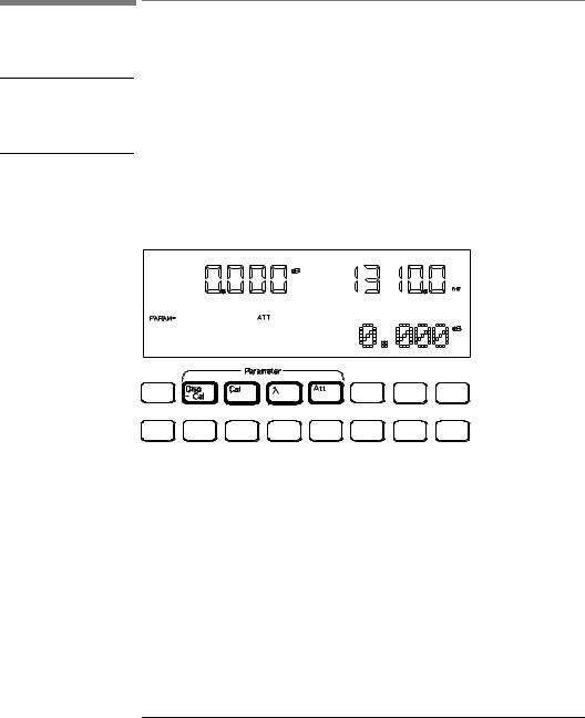
Figure 1-1
Getting Started
Using the Attenuator
1.1 Using the Attenuator
Before using the instrument, you should make sure that it is properly warmed up. The instrument is properly warmed up when it has been switched on for a minimum of 45 minutes. Failure to do this can cause errors of up to 0.04dB in the attenuation.
Set the attenuation of the filter using ATT (attenuation factor), λ (wavelength), and CAL (calibration factor).
The Attenuator Keys
The attenuation factor and the calibration factor set the position of the filter. The calibration factor allows you to offset the value of the attenuation factor.
Att(dB) = Cal(dB) + Attenuationfilter(dB)
In addition, you can use DISP→ CAL to transfer the current attenuation factor to the calibration factor.
Using the Modify Keys
There are four modify keys on the front panel of the attenuator.
29

|
Getting Started |
|
Making an Attenuation Sweep |
Figure 1-2 |
The Modify Keys |
Editing a Number
Use and to move the cursor from digit to digit when editing a number. Use and to change the value of a digit when editing a number.
Editing a Non-Numeric Parameter
Use or to increment the parameter.
Use or to decrement the parameter.
1.2 Making an Attenuation Sweep
There are two types of attenuation sweep, automatic and manual.
Making an Automatic Sweep
An automatic sweep is one where stepping from one attenuation factor to the next is done by the instrument.
To select the automatic sweep press SWP, and make sure that
SWEEP is set to AUTO. By pressing SWP repeatedly you view and
30
Loading...