


 Loading...
User’s Guide
AC Power Solutions
Agilent Models 6811B, 6812B, and 6813B
For instruments with Serial Numbers:
Agilent 6811B: US38390101-up
Agilent 6812B: US38390101-up
Agilent 6813B: US38390101-up
Agilent Part No. 5962-0829 |
Printed in U.S.A. |
Microfiche No 5962-0830 |
December, 1998 |
|
Update April 2000 |

Warranty Information
CERTIFICATION
Agilent Technologies certifies that this product met its published specifications at time of shipment from the factory. Agilent Technologies further certifies that its calibration measurements are traceable to the United States National Bureau of Standards, to the extent allowed by the Bureau’s calibration facility, and to the calibration facilities of other International Standards Organization members.
WARRANTY
This Agilent Technologies hardware product is warranted against defects in material and workmanship for a period of three years from date of delivery. Agilent Technologies software and firmware products, which are designated by Agilent Technologies for use with a hardware product and when properly installed on that hardware product, are warranted not to fail to execute their programming instructions due to defects in material and workmanship for a period of 90 days from date of delivery. During the warranty period Agilent Technologies will, at its option, either repair or replace products which prove to be defective. Agilent Technologies does not warrant that the operation for the software firmware, or hardware shall be uninterrupted or error free.
For warranty service, with the exception of warranty options, this product must be returned to a service facility designated by Agilent Technologies. Customer shall prepay shipping charges by (and shall pay all duty and taxes) for products returned to Agilent Technologies for warranty service. Except for products returned to Customer from another country, Agilent Technologies shall pay for return of products to Customer.
Warranty services outside the country of initial purchase are included in Agilent Technologies product price, only if Customer pays Agilent Technologies international prices (defined as destination local currency price, or U.S. or Geneva Export price).
If Agilent Technologies is unable, within a reasonable time to repair or replace any product to condition as warranted, the Customer shall be entitled to a refund of the purchase price upon return of the product to Agilent Technologies.
LIMITATION OF WARRANTY
The foregoing warranty shall not apply to defects resulting from improper or inadequate maintenance by the Customer, Customer-supplied software or interfacing, unauthorized modification or misuse, operation outside of the environmental specifications for the product, or improper site preparation and maintenance. NO OTHER WARRANTY IS EXPRESSED OR IMPLIED. AGILENT TECHNOLOGIES SPECIFICALLY DISCLAIMS THE IMPLIED WARRANTIES OF MERCHANTABILITY AND FITNESS FOR A PARTICULAR PURPOSE.
EXCLUSIVE REMEDIES
THE REMEDIES PROVIDED HEREIN ARE THE CUSTOMER’S SOLE AND EXCLUSIVE REMEDIES. AGILENT TECHNOLOGIES SHALL NOT BE LIABLE FOR ANY DIRECT, INDIRECT, SPECIAL, INCIDENTAL, OR CONSEQUENTIAL DAMAGES, WHETHER BASED ON CONTRACT, TORT, OR ANY OTHER LEGAL THEORY.
ASSISTANCE
The above statements apply only to the standard product warranty. Warranty options, extended support contacts, product maintenance agreements and customer assistance agreements are also available. Contact your nearest Agilent Technologies Sales and Service office for further information on Agilent Technologies’ full line of Support Programs.
2

Safety Summary
The following general safety precautions must be observed during all phases of operation of this instrument. Failure to comply with these precautions or with specific warnings elsewhere in this manual violates safety standards of design, manufacture, and intended use of the instrument. Agilent Technologies assumes no liability for the customer’s failure to comply with these requirements.
WARNING: LETHAL VOLTAGES
Ac sources can supply 425 V peak at their output. DEATH on contact may result if the output terminals or circuits connected to the output are touched when power is applied.
GENERAL
This product is a Safety Class 1 instrument (provided with a protective earth terminal). The protective features of this product may be impaired if it is used in a manner not specified in the operation instructions.
Any LEDs used in this product are Class 1 LEDs as per IEC 825-1.
ENVIRONMENTAL CONDITONS
This instrument is intended for indoor use in an installation category II, pollution degree 2 environment. It is designed to operate at a maximum relative humidity of 95% and at altitudes of up to 2000 meters. Refer to the specifications tables for the ac mains voltage requirements and ambient operating temperature range.
BEFORE APPLYING POWER
Verify that the product is set to match the available line voltage, the correct fuse is installed, and all safety precautions are taken. Note the instrument’s external markings described under "Safety Symbols".
GROUND THE INSTRUMENT
To minimize shock hazard, the instrument chassis and cover must be connected to an electrical ground. The instrument must be connected to the ac power mains through a grounded power cable, with the ground wire firmly connected to an electrical ground (safety ground) at the power outlet. Any interruption of the protective (grounding) conductor or disconnection of the protective earth terminal will cause a potential shock hazard that could result in personal injury.
ATTENTION: Un circuit de terre continu est essentiel en vue du fonctionnement sécuritaire de l’appareil. Ne jamais mettre l'appareil en marche lorsque le conducteur de mise … la terre est d‚branch‚.
FUSES
Only fuses with the required rated current, voltage, and specified type (normal blow, time delay, etc.) should be used. Do not use repaired fuses or short-circuited fuseholders. To do so could cause a shock or fire hazard.
DO NOT OPERATE IN AN EXPLOSIVE ATMOSPHERE
Do not operate the instrument in the presence of flammable gases or fumes.
DO NOT REMOVE THE INSTRUMENT COVER
Operating personnel must not remove instrument covers. Component replacement and internal adjustments must be made only by qualified service personnel.
Instruments that appear damaged or defective should be made inoperative and secured against unintended operation until they can be repaired by qualified service personnel.
3
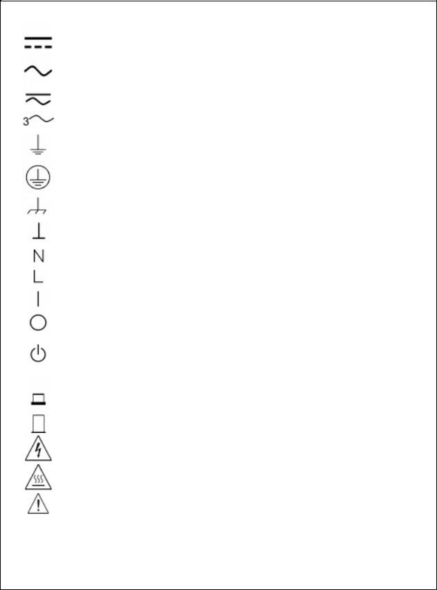
SAFETY SYMBOLS
WARNING
Caution
Direct current
Alternating current
Both direct and alternating current
Three-phase alternating current
Earth (ground) terminal
Protective earth (ground) terminal
Frame or chassis terminal
Terminal is at earth potential. Used for measurement and control circuits designed to be operated with one terminal at earth potential.
Terminal for Neutral conductor on permanently installed equipment
Terminal for Line conductor on permanently installed equipment
On (supply)
Off (supply)
Standby (supply). Units with this symbol are not completely disconnected from ac mains when this switch is off. To completely disconnect the unit from ac mains, either disconnect the power cord or have a qualified electrician install an external switch.
In position of a bi-stable push control
Out position of a bi-stable push control
Caution, risk of electric shock
Caution, hot surface
Caution (refer to accompanying documents)
The WARNING sign denotes a hazard. It calls attention to a procedure, practice, or the like, which, if not correctly performed or adhered to, could result in personal injury. Do not proceed beyond a WARNING sign until the indicated conditions are fully understood and met.
The CAUTION sign denotes a hazard. It calls attention to an operating procedure, or the like, which, if not correctly performed or adhered to, could result in damage to or destruction of part or all of the product. Do not proceed beyond a CAUTION sign until the indicated conditions are fully understood and met.
4

Declaration Page
DECLARATION OF CONFORMITY
according to ISO/IEC Guide 22 and EN 45014
Manufacturer’s Name: |
Agilent Technologies, Inc. |
Manufacturer’s Address: |
140 Green Pond Road |
|
Rockaway, New Jersey 07866 |
|
U.S.A. |
declares that the Product |
|
Product Name: |
a) AC Power Source/Analyzer |
|
b) Harmonic/Flicker Test System |
Model Number(s): |
a) Agilent 6811B, 6813B, 6812B, 6811A, 6812A, 6813A |
|
b) Agilent 6841A, 6842A |
conforms to the following Product Specifications: |
|
Safety: |
IEC 1010-1:1990+A1(1992) / EN 61010-1:1993 |
EMC: |
CISPR 11:1990 / EN 55011:1991 - Group 1 Class A |
|
IEC 801-2:1991 / EN 50082-1:1992 - 4 kV CD, 8 kV AD |
|
IEC 801-3:1984 / EN 50082-1:1992 - 3 V / m |
|
IEC 801-4:1988 / EN 50082-1:1992 - 0.5 kV Signal Lines |
|
1 kV Power Lines |
Supplementary Information:
The product herewith complies with the requirements of the Low Voltage Directive 73/23/EEC and the EMC Directive 89/336/EEC and carries the CE-marking accordingly.
New Jersey |
January 1997 |
__ |
|
__ |
Location |
Date |
|
Bruce Krueger / Quality Manager |
|
European Contact: Your local Agilent Technologies Sales and Service Office or Agilent Technologies GmbH, Department TRE, Herrenberger Strasse 130, D-71034 Boeblingen (FAX:+49-7031-14-3143)
5

Acoustic Noise Information
Herstellerbescheinigung
Diese Information steht im Zusammenhang mit den Anforderungen der
Maschinenläminformationsverordnung vom 18 Januar 1991.
*Schalldruckpegel Lp <70 dB(A)
*Am Arbeitsplatz
*Normaler Betrieb
*Nach EN 27779 (Typprüfung).
Manufacturer’s Declaration
This statement is provided to comply with the requirements of the German Sound Emission Directive, from 18 January 1991.
*Sound Pressure Lp <70 dB(A)
*At Operator Position
*Normal Operation
*According to EN 27779 (Type Test).
Printing History
The edition and current revision of this manual are indicated below. Reprints of this manual containing minor corrections and updates may have the same printing date. Revised editions are identified by a new printing date. A revised edition incorporates all new or corrected material since the previous printing date.
Changes to the manual occurring between revisions are covered by change sheets shipped with the manual. In some cases, the manual change applies only to specific instruments. Instructions provided on the change sheet will indicate if a particular change applies only to certain instruments.
This document contains proprietary information protected by copyright. All rights are reserved. No part of this document may be photocopied, reproduced, or translated into another language without the prior consent of Agilent Technologies. The information contained in this document is subject to change without notice.
© Copyright 1995, 1997, 1998 Agilent Technologies, Inc. |
Edition 1 _________August, 1995 |
|
|
Edition 2 |
_________February, 1997 |
|
Edition 3 |
_________March, 1998 |
|
Edition 4 |
_________December 1998 |
|
Update |
_________April 2000 |
6

Table of Contents
Warranty Information |
2 |
Safety Summary |
3 |
Declaration of Conformity |
5 |
Acoustic Noise Information |
6 |
Printing History |
6 |
Table of Contents |
7 |
1 GENERAL INFORMATION |
11 |
Document Orientation |
11 |
Earlier AC Source Models |
12 |
Safety Considerations |
12 |
Options and Parts |
12 |
Description |
13 |
Capabilities |
14 |
Front Panel/Remote Operation |
14 |
Steady-state Output Characteristic |
15 |
Peak Current/Dynamic Power Capability |
16 |
Peak Current Limit |
16 |
Peak Inrush Example |
16 |
RMS Current Limit Circuit |
17 |
Voltage Regulation |
18 |
Real Time Regulation |
18 |
RMS Regulation |
18 |
Output Impedance |
18 |
Output Coupling |
19 |
2 INSTALLATION |
21 |
Inspection |
21 |
Damage |
21 |
Packaging Material |
21 |
Items Supplied |
21 |
Cleaning |
21 |
Location |
22 |
Bench Operation |
22 |
Rack Mounting |
22 |
Input Connections |
23 |
Input Source and Line Fuse |
23 |
Installing the Power Cord |
23 |
Output Connections |
24 |
Wire Considerations |
25 |
Voltage Drops |
25 |
Remote Sense Connections |
25 |
Remote Sensing and OVP Considerations |
27 |
Trigger Connections |
27 |
Digital Connections |
27 |
Controller Connections |
28 |
GPIB Connector |
28 |
RS-232 Interface |
28 |
7
3 TURN-ON CHECKOUT |
31 |
Introduction |
31 |
Preliminary Checkout |
31 |
Using the Keypad |
32 |
Checkout Procedure |
32 |
In Case of Trouble |
34 |
Error Messages |
34 |
Line Fuse |
35 |
4 FRONT PANEL OPERATION |
37 |
|
Introduction |
37 |
|
Front Panel Description |
37 |
|
System Keys |
39 |
|
Function Keys |
40 |
|
Immediate Action Keys |
40 |
|
Scrolling Keys |
40 |
|
Meter Display Keys |
41 |
|
Output Control Keys |
42 |
|
Protection and Status Control Keys |
44 |
|
Trigger and List Control Keys |
45 |
|
Entry Keys |
46 |
|
Examples of Front Panel Programming |
47 |
|
1 |
- Setting the Output Voltage Amplitude |
47 |
2 |
- Setting the Output Frequency |
47 |
3 |
- Setting the DC Offset |
48 |
4 |
- Setting a Protection Feature |
48 |
5 |
- Clearing Protection Conditions |
49 |
6 |
- Using Transient Voltage Modes |
50 |
7 |
- Trigger Delays and Phase Synchronization |
53 |
8 |
- Using Slew Rates to Generate Waveforms |
55 |
9 |
- Measuring Peak Inrush Current |
57 |
10 - Setting the GPIB Address and RS-232 Parameters |
58 |
|
11 - Saving and Recalling Operating States |
58 |
|
A SPECIFICATIONS |
59 |
Specifications |
59 |
Supplemental Characteristics |
61 |
Operation Below 45 Hz |
53 |
B VERIFICATION AND CALIBRATION |
65 |
Introduction |
65 |
Equipment Required |
65 |
Test Setup |
66 |
Performing the Verification Tests |
67 |
Turn-On Checkout Procedure |
67 |
AC Voltage Programming and Measurement Accuracy |
67 |
DC Voltage Programming and Measurement Accuracy |
68 |
RMS Current Accuracy Test |
68 |
Performing the Calibration Procedure |
71 |
Front Panel Calibration Menu |
71 |
Front Panel Calibration |
72 |
8
Enable Calibration Mode |
72 |
Calibrating and Entering Voltage Offset Values |
72 |
Calibrating and Entering DC Voltage Gain Values |
73 |
Calibrating and Entering AC rms Voltage Gain Values |
73 |
Calibrating the OVP Trip Point |
74 |
Calibrating and Entering rms Current Values |
74 |
Calibrating and Entering rms Current Measurement Values |
75 |
Calibrating the Output Impedance |
75 |
Saving the Calibration Constants |
75 |
Changing the Calibration Password |
76 |
Calibration Error Messages |
76 |
Calibration Over the GPIB |
76 |
Agilent Calibration Program Listing |
76 |
C ERROR MESSAGES |
81 |
Error Number List |
81 |
D LINE VOLTAGE CONVERSION |
85 |
Open the Unit |
85 |
Check the Jumper Wire (Model Agilent 6811B/6812B only) |
85 |
Check the Line Jumpers (all Models) |
85 |
Check the Power Transformer Connector (all Models) |
85 |
Close the Unit |
86 |
INDEX |
87 |
9
1
General Information
Document Orientation
This manual describes the operation of the Agilent 6811B/6812B/6813B AC Power Solutions. These units will be referred to as "ac sources" throughout this manual. The following documents are shipped with your ac source:
♦a Quick-Start Guide, to help you quickly get started using the ac source
♦a User’s Guide, containing detailed installation, checkout, and front panel information
♦a Programming Guide, containing detailed GPIB programming information
♦a Quick Reference Card, designed as a memory jogger for the experienced user
You will find information on the following tasks in these guides. Refer to the table of contents of each guide for a complete list of the topics.
Topic
Accessories and Options Calibrating the ac source Front panel keys
Front panel programming examples Line voltage connections
Line voltage ratings Line voltage conversion
Operator replaceable parts Operator troubleshooting Operating characteristics Performance specifications Quick operating checkout Rack mounting
RS-232 operation
SCPI programming examples SCPI programming commands Turn-on/checkout
Wiring - discrete fault indicator (DFI)
-GPIB controller
-load or loads
-voltage sensing (local and remote)
-remote inhibit (RI)
Location
Chapter 1 - this guide Appendix B - this guide Chapter 4 - this guide Chapter 4 - this guide Chapter 2 - this guide Appendix A - this guide Appendix D - this guide Chapter 1 - this guide Chapter 3 - this guide Appendix A - this guide Appendix A - this guide Chapter 3 - this guide Chapter 2 - this guide Chapter 2 - this guide
Chapter 3 - Programming Guide Chapter 4 - Programming Guide Chapter 3 - this guide
Chapter 2 - this guide Chapter 2 - this guide Chapter 2 - this guide Chapter 2 - this guide Chapter 2 - this guide
11
1 - General Information
Earlier AC Source Models
With the exception of some minor readback specification differences, information in this manual also applies to the following earlier ac source models:
Information about this current model
Agilent 6811B
Agilent 6812B
Agilent 6813B
also applies to the following earlier models:
Agilent 6811A AC Power Source/Analyzer
Agilent 6812A AC Power Source/Analyzer Agilent 6841A Harmonic/Flicker Test System in normal mode
Agilent 6813A AC Power Source/Analyzer Agilent 6842A Harmonic/Flicker Test System in normal mode
Safety Considerations
This ac source is a Safety Class 1 instrument, which means it has a protective earth terminal. That terminal must be connected to earth ground through a power source equipped with a ground receptacle. Refer to the Safety Summary page at the beginning of this guide for general safety information. Before installation or operation, check the ac source and review this guide for safety warnings and instructions. Safety warnings for specific procedures are located at appropriate places in the guide.
Options and Parts
|
|
Table 1-1. Options |
|
Option |
Model |
|
Description |
0BN |
All |
|
Extra documentation |
1CM |
All |
|
Rack mount kit (Agilent p/n 5062-3977) |
1CP |
All |
|
Rack mount kit with handles (Agilent p/n 5062-3983) |
100 |
Agilent 6811B/6812B |
|
87-106 Vac, 48-63 Hz (Japan only) |
200 |
Agilent 6813B |
|
174-106 Vac, 48-63 Hz (Japan only) |
230 |
Agilent 6811B/6812B |
|
191-254 Vac, 48-63 Hz |
831 |
Agilent 6812B/6813B |
|
12 AWG, 200 to 240 Vac, unterminated |
832 |
Agilent 6813B |
|
4-mm2 wire size, unterminated |
833 |
Agilent 6812B |
|
1.5-mm2 wire size, 200 to 240 Vac, unterminated |
834 |
Agilent 6812B |
|
10 AWG, 100 to 120 Vac, unterminated |
841 |
Agilent 6812B/6813B |
|
Line cord with NEMA 6-20P; 20A, 250 V plug |
842 |
Agilent 6813B |
|
Line cord with IEC 309; 32A, 220 V plug |
844 |
Agilent 6813B |
|
Line cord with NEMA 6-30P; 30A, 250 V locking plug |
845 |
Agilent 6812B |
|
Line cord with IEC 309; 16 A, 220 V plug |
846 |
Agilent 6812B |
|
Line cord with NEMA L5-30P; 30 A, 120 V plug |
847 |
Agilent 6812B |
|
Line cord with CEE 7/7; 16 A, 220 V plug |
848 |
Agilent 6812B |
|
Line cord with BS 546; 15 A, 240 V plug |
Support rails (Agilent p/n 1494-0059) are required when rack mounting units with options 1CM and 1CP.
Agilent 6811B units are shipped with the correct line cord for the destination country.
12
General Information - 1
The following table lists some common user-replaceable parts:
Table 1-2. Operator Replaceable Parts
Item |
Agilent Part Number |
Power cord assembly |
see "Options" |
Rack mount kit |
see "Options" |
4-terminal digital connector plug |
1252-1488 |
Ac input safety cover (with strain relief and bushing) |
5040-1676 |
Screw (3), ac input barrier block (6-32 x 5/16in) |
N/A |
Ac output safety cover |
5040-1704 |
Line fuse for Agilent 6812B (30 AM) |
2110-0910 |
Line fuse for Agilent 6813B (25 AM) |
2110-0849 |
Line fuse for Agilent 6811B (20 AM) |
2110-0098 |
Screw (2), ac output safety cover (m4 x 0.7in) |
0515-0053 |
Screw (5), ac output barrier block (6-32 x 5/16 in) |
N/A |
User’s Guide (this manual) |
5962-0829 |
Programming Guide |
5962-0889 |
Quick Start Guide |
5962-0883 |
Quick Reference Card |
5962-0885 |
Description
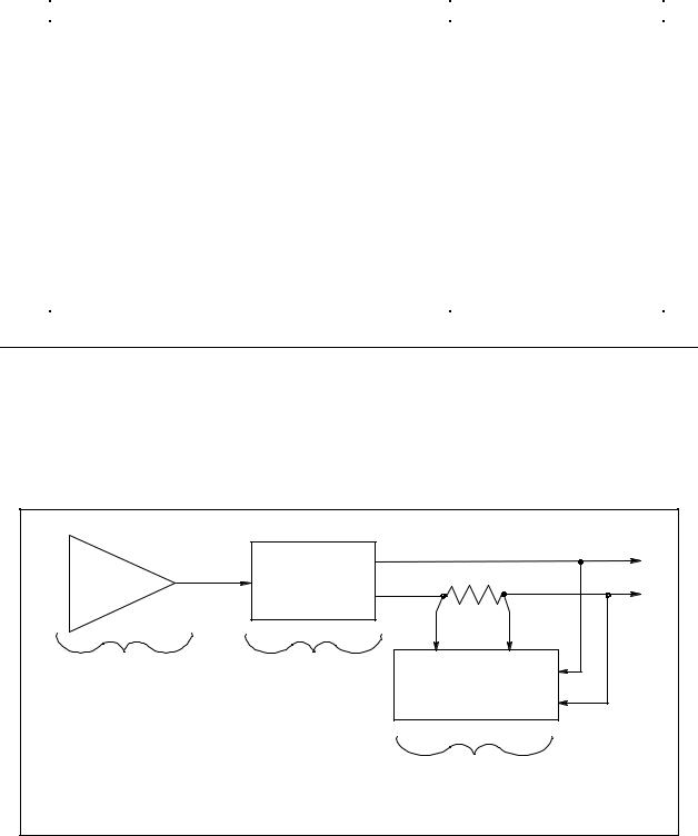
The ac source combines three instruments in one unit as shown in the following figure. The function generator produces waveforms with programmable amplitude, frequency, and shape. The power amplifier amplifies the function generator signal to produce the ac power for your application. The measurement functions range from a simple readback of rms voltage and current, to sophisticated capabilities such as waveform analysis.
DAC |
SOURCE |
shunt |
|
WAVEFORM |
BIPOLAR |
MEASUREMENT |
GENERATOR |
AMPLIFIER |
BLOCK |
POWERMETER
FFT ANALYZER
Figure 1-1. AC Source Functional Elements
13

1 - General Information
The following model ac power sources are described in this User’s Guide:
Model |
Description |
Agilent 6811B |
0-300 V rms; 375 VA (425 V peak; 40 A peak) |
Agilent 6812B |
0-300 V rms; 750 VA (425 V peak; 40 A peak) |
Agilent 6813B |
0-300 V rms; 1750 VA (425 V peak; 80 A peak) |
Capabilities
♦Programmable ac voltage, dc voltage, frequency, phase, and current limit.
♦Sine, square, clipped sine, and user-definable waveforms.
♦Programmable output impedance.
♦Voltage and frequency slew control.
♦Synthesized waveform generation for high resolution and accuracy in frequency, low waveform distortion, and glitch-free phase transitions.
♦Step and pulse output transients for generating surge, sag, dropout, and other line disturbance simulations.
♦Nonvolatile list programming for generating complex output transients or test sequences.
♦Nonvolatile state and waveform storage and recall.
♦Extensive measurement capability:
Ac rms, dc, ac+dc voltage and current and peak current. Real, reactive, and apparent power.
Harmonic analysis of voltage and current waveforms gives amplitude, phase, and total harmonic distortion results up to the 50th harmonic.
Triggered acquisition of digitized voltage and current with extensive post-acquisition calculations.
All measurements made with 16-bit resolution.
♦Trigger In and Trigger Out for synchronizing transient events or measurements with external signals.
♦Front panel control with 14-character vacuum flourescent display, keypad, and rotary pulse generators for voltage and frequency settings.
♦Built-in GPIB and RS-232 interface programming with SCPI command language.
♦Over-voltage, over-power, over-current, over-temperature, and RI/DFI protection features.
♦Built-in output and sense disconnect relays.
♦Output terminals floating with respect to chassis ground.
♦Extensive selftest, status reporting, and software calibration.
Front Panel/Remote Operation
The front panel has both rotary (RPG) and keypad controls for setting the output voltage and frequency. The panel display provides digital readouts of a number of output measurements. Annunciators display the operating status of the ac source. System keys let you perform system functions such as setting the GPIB address and recalling operating states. Front panel Function keys access the ac source function menus. Front panel Entry keys let you select and enter parameter values. Refer to Chapter 4 for a complete description of the front panel controls.
14
General Information - 1
Remotely programming is accomplished from either the GPIB bus or from an RS-232 serial port. GPIB and RS-232 programming uses SCPI commands (Standard Commands for Programmable Instruments) that make the ac source programs compatible with those of other instruments. AC source status registers permit remote monitoring of a wide variety of ac source operating conditions
NOTE: Refer to the ac source Programming Guide for further information about remotely programming the ac source.
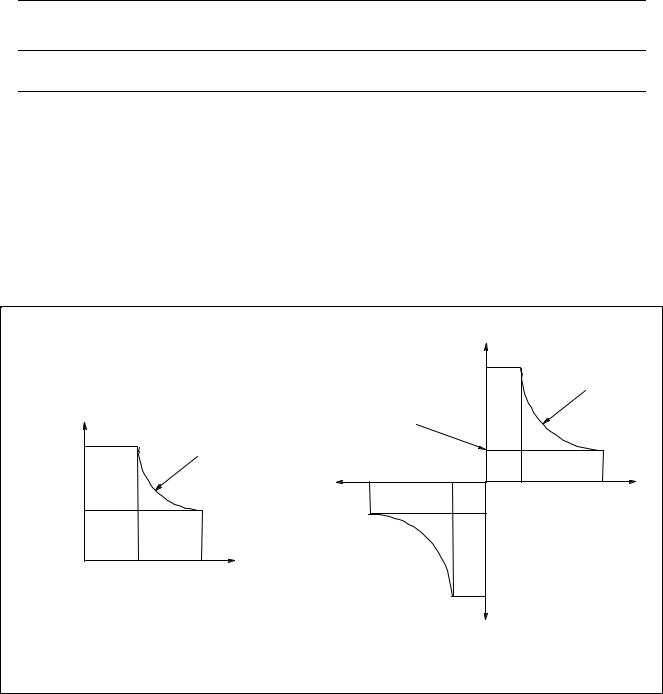
Steady-state Output Characteristic
The ac source’s steady-state output characteristic is shown in the following figure. Steady-state characteristics are defined as those output ratings that will be maintained by the ac source for an indefinite time. (The section "Peak Current Capability" describes the dynamic output capability of the unit.) The figure shows both the ac and the dc characteristics. With programmable output coupling, the ac source can supply dc as well as ac output voltages.
Ac source operation is specified from 45 to 1000 Hz (see Appendix A). However, you can operate the unit at frequencies less that 45 Hz. The operating characteristics of the ac source at autput frequencies below 45 Hz are documented in Table A-3 of Appendix A.
|
|
Vdc |
|
|
|
424 V |
285W (6811B) |
|
|
|
|
|
|
|
575W (6812B) |
|
|
|
1350W (6813B) |
Vrms |
|
115V (6811B/6812B) |
|
|
|
135V (6813B) |
|
300 V |
375VA (6811B) |
|
|
750VA (6812B) |
|
|
|
|
|
|
|
|
1750VA (6813B) |
-2.5A (6811B) |
|
|
|
Idc |
|
|
-Idc |
-5A (6812B) |
|
|
0 |
|
|
|
-10A (6813B) |
|
|
|
|
0.67A (6811B) |
2.5A (6811B) |
115V (6811B/6812B) |
|
1.35A (6812B) |
5A (6812B) |
|
|
||
135V (6813B) |
|
3.17A (6813B) |
10A (6813B) |
0 |
Irms |
|
|
|
|
|
|
1.25A (6811B) |
3.25A (6811B) |
|
|
2.5A (6812B) |
6.5A (6812B) |
|
|
5.8A (6813B) |
13A (6813B) |
-424 V |
|
-Vdc
AC CHARACTERISTIC |
DC CHARACTERISTIC |
|
(45Hz - 1kHz sinewave)
Figure 1-2. Steady-state Output Characteristic (in real-time mode)
15

1 - General Information
Peak Current/Dynamic Power Capability
The ac source can generate peak currents that exceed the rms current capability of the unit. This not only applies when operating in ac mode, but also when programming output pulses in dc mode. Although the unit will generate peak output currents up to 40A (Agilent 6811B/6812B) or 80A (Agilent 6813B), the unit can only maintain this output for a limited time. If the output of the unit exceeds the limit of the safe operating area (SOA), the unit will activate its internal protection mode and turn its output off. This SOA limit is based on output voltage, output current, output duration, and heatsink temperature.
NOTE: Refer to Chapter 4 on how to clear the unit when the internal protection mode has been activated.
Peak Current Limit
By programming the peak current limit, you can prevent the unit from exceeding the safe operating area, activating its internal protection mode, and turning the output off. The peak current limit circuit limits the instantaneous output current. It functions by reducing the instantaneous output voltage to keep the output peak current within the programmed limit. Because the circuit acts instantly, the effect is that it will clip the peaks of the output voltage waveform. Additionally, with fast and/or large voltage transitions, the unit may momentarily go into CC operating mode due to current in the output capacitor. This serves to limit the rate of change of output voltage.
The following table gives approximate indications of how long the unit will tolerate peak output currents before the SOA limits are exceeded. Because these values are voltage dependent, the table includes various equivalent dc voltages along with the peak current values. The voltages shown in the table are NOT the programmed voltages, but the average voltage values that will appear at the output when the indicated high current condition exists. The SOA circuit becomes active at higher voltage and current values as well as at longer duration times.
|
Table 1-3. Typical Peak Current Output Capacities |
|
|
|
|||||
Agilent |
Agilent 6811B |
|
equivalent dc voltage when current is flowing 1 |
|
|||||
6813B |
Agilent 6812B |
25 |
75 |
125 |
190 |
|
250 |
|
360 |
20 A |
10 A |
>100 ms |
>100 ms |
>100 ms |
>100 ms |
|
>100 ms |
|
>100 ms |
30 A |
15 A |
>100 ms |
100 ms |
30 ms |
24 ms |
|
19 ms |
|
15 ms |
40 A |
20 A |
12 ms |
9.2 ms |
8.4 ms |
7.6 ms |
|
6.8 ms |
|
5.9 ms |
50 A |
25 A |
5.6 ms |
5.1 ms |
4.7 ms |
4.4 ms |
|
4 ms |
|
3.5 ms |
60 A |
30 A |
3.7 ms |
3.4 ms |
3.1 ms |
2.9 ms |
|
2.6 ms |
|
2.3 ms |
70 A |
35 A |
2.6 ms |
2.4 ms |
2.2 ms |
2.1 ms |
|
1.9 ms |
|
1.7 ms |
80 A |
40 A |
2 ms |
1.8 ms |
1.7 ms |
1.6 ms |
|
1.4 ms |
|
1.3 ms |
1Based on 25C ambient temperature, with heatsink temperature less than 50C.
Peak Inrush Example
The following table gives the recommended initial Ipeak settings when the ac source output is a 127 Vac or 254 Vac 60 Hz sine wave, as a function of load capacitance. The load on the output is a full-wave bridge along with the indicated capacitor. The load resistance across the capacitor is infinite. The recommended Ipeak will change as a function of changes in input as follows:
16
General Information - 1
♦as voltage increases, the Ipeak setting needs to be decreased.
♦as frequency increases, the Ipeak setting can be increased.
♦as load resistance decreases, the Ipeak setting needs to be decreased.
Note that the purpose of programming the Ipeak current is to prevent the unit from activating its internal protection mode as a result of exceeding the SOA limits, and turning the output off. These initial settings may have to be reduced if the SOA circuit trips when the output is turned on. Sometimes trial and error must be used to arrive at the proper values of Ipeak.
Table 1-4. Recommended Ipeak Settings as a Function of Loop Capacitance
Capacitance in μF |
Ipeak setting |
|
127 V |
254 V |
|
≤ 1100 |
500 |
80 A |
1200 |
- |
60 A |
1700 |
700 |
50 A |
5000 |
1000 |
45 A |
> 5000 |
> 1000 |
< 45 A |
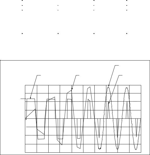
The following waveform illustrates the inrush current capability of the ac source. The peak current is limited during inrush in accord with table 1-3 to keep the ac source from turning its output off. Note that the output current waveform returns to its normal shape when the current drops below the peak current limit setting.
VOLTAGE IS
UNDISTORTED
|
|
(115 |
Vrms) |
|
CURRENT |
VOLTAGE |
|
PEAK CURRENT |
|
WAVEFORM |
WAVEFORM |
|
||
< |
45 A |
|||
|
|
I PEAK=45A
0
Figure 1-3. Peak Inrush Current Example
17

1 - General Information
RMS Current Limit Circuit
The output rms current limit is adjustable to any value within the range of the unit. If the load attempts to draw more current than the programmed limit, the output voltage is reduced to keep the rms current within the limit. When the output voltage is reduced, the waveform shape is preserved. In other words, all parts of the voltage cycle are reduced -- not just the peaks.
NOTE: The speed at which the rms current circuit operates depends on the output voltage setting and the load impedance. The circuit responds more slowly at low output voltages and at high output impedances. With constant power or negative resistance loads, the rms current limit circuit causes the output voltage to go to zero.
Voltage Regulation
Real Time Regulation
The default method of output regulation used by the ac source is real-time voltage regulation. Real-time voltage regulation tries to provide the actual programmed waveform at the output of the ac source. It offers the best overall programming response and fastest settling times. It does not have any limitations for waveforms and transients with frequency content below 45 Hz.
RMS Regulation
Rms voltage regulation assists real-time regulation to level out or stabilize the rms value of the ac component of the output voltage. Use rms voltage regulation in the following situations:
♦If you experience load regulation effects with heavy loads.
♦If you experience frequency regulation problems with heavy loads and you require flatter programming accuracy at higher frequencies.
♦In conjunction with programmable output impedance, if you wish to maintain the rms level of output voltage as the source impedance is increases. (Refer to Output Impedance for more information.)
The command to specify voltage regulation is VOLT:ALC:DET RTIM | RMS.
NOTE: Do not use rms voltage regulation when operating at frequencies less than 45 Hz.
Output Impedance
You can program the real and/or reactive (resistive and/or inductive) part of the output impedance of the ac source. Inductive output impedances can be programmed in the range of 20 to 1000 microhenries. Resistive load impedances can be programmed in the range of 0 to 1 ohms.
When programming output impedances, the lower your load impedance, the LESS programmed impedance you can use and still maintain output voltage stability. This applies particularly for load impedances less than 1 ohm.
18

General Information - 1
CAUTION: Programming the ac source output impedance into a load with a low impedance can cause output voltage instability, which may damage the ac source. Stability MUST be maintained when operating the ac source with programmable resistance or inductance.
To check for stability, monitor the output voltage with an oscilloscope. Instability exists if a 5kHz to 20kHz oscillation, which is dependent upon the ac source’s programmed inductance and the capacitance of the load, is present at any time during the following procedure.
1.When programming inductance, it is recommended that you first add a series resistance either by programming the output resistance to 1 ohm or by adding an equivalent external resistor.
2.Slowly program the inductance to the desired level while monitoring the output for any voltage instability. Do not proceed any further if the output shows any signs of instability.
3.If less output resistance is required, slowly start lowering the resistance while monitoring the output for any voltage instability. Do not proceed any further if the output shows any signs of instability.
If you cannot achieve satisfactory results with this procedure, disable the output impedance control and use an external impedance network.
Rms voltage regulation can be used in conjunction with programmable output impedance to regulate the rms value of the ac component of the output voltage when programmed impedances cause distortion with nonlinear loads or reduced output voltage due to regulation effects.
Note that real-time voltage regulation will permit the load current to cause output voltage degradation based on the programmed impedance and current drawn from the source, whereas rms regulation will reestablish the rms value at the programmed level.
Output Coupling
Ac output coupling mode mimics a transformer-coupled output, working to maintain zero average output voltage. This means that the output tries to remove any dc content on the output, whether the dc content is generated from a programmed offset or results from transients with dc content. The ac output coupling has a corner frequency of about 2 Hz, which will not prevent transient waveforms that may have short-term dc content, but will regulate the waveform back to an average value of zero volts in the steady state.
Dc output coupling mode is used to generate dc offset voltages or output transients that have net dc components. In either mode of operation, the maximum voltage that the ac source can output is limited to 425 V peak.
The ac capability of the output is limited by VA (volt-amperes) rather than power (watts). The amount of VA available to a load can be determined by examining figure 1-2. Full output VA is available with no limitations except for the boundaries imposed by the maximum rms voltage of 300V, and the maximum rms current, which is model-dependent. Note that large peak power transients can be delivered by the ac source as earlier described under "Peak Current Capability"(Appendix A documents the ac source’s specifications and supplemental characteristics.)
19
2
Installation
Inspection
Damage
When you receive your ac source, inspect it for any obvious damage that may have occurred during shipment. If there is damage, notify the shipping carrier and the nearest Agilent Sales and Support Office immediately. The list of Agilent Sales and Support Offices is at the back of this guide. Warranty information is printed in the front of this guide.
Packaging Material
Until you have checked out the ac source, save the shipping carton and packing materials in case the unit has to be returned. If you return the ac source for service, attach a tag identifying the model number and the owner. Also include a brief description of the problem.
Items Supplied
Check that the following items are included with your ac source. Some items are installed in the unit.
Power Cord |
A power cord appropriate for your location. The cord may or may not be |
|
terminated in a power plug (see "Options" in Chapter 1). If the cord is not |
|
included, contact your nearest Agilent Sales and Support Office (refer to the |
|
list at the back of this guide). |
Digital connector |
4-terminal digital plug that connects to the back of the unit. |
Safety covers |
Ac input cover with strain relief |
|
Ac output cover |
Manuals |
User’s Guide |
|
Programming Guide |
|
Quick Start Guide |
|
Quick Reference Card |
Change page |
If applicable, change sheets may be included with this guide. If there are |
|
change sheets, make the indicated corrections in this guide. |
Cleaning
Use a dry cloth or one slightly dampened with water to clean the external case parts. Do not attempt to clean internally.
WARNING: To prevent electric shock, unplug the unit before cleaning.
21
2 - Installation
Location
Refer to the Safety Summary page at the beginning of this manual for safety-related information about environmental conditions.
CAUTION: Agilent 6811B/6812B units weigh 28.2 kg (62 lbs). Agilent 6813B units weigh 32.7 kg (72 lbs).
Obtain adequate help when moving or mounting the unit in the rack.
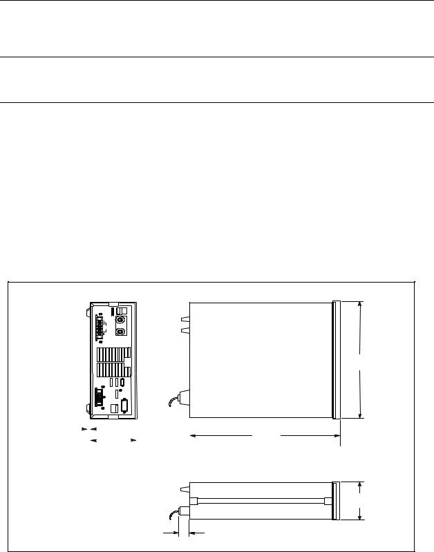
Bench Operation
The outline diagram in figure 2-1 gives the dimensions of your ac source. The feet may be removed for rack mounting. Your ac source must be installed in a location that allows sufficient space at the sides and back of the unit for adequate air circulation. Minimum clearances are 1 inch (25 mm) along the sides. Do not block the fan exhaust at the rear of the unit.
Rack Mounting
The ac source can be mounted in a standard 19-inch rack panel or cabinet. Rack mounting kits are available as Option 1CM or 1CP. Installation instructions are included with each rack mounting kit.
Agilent ac sources also require instrument support rails in addition to the rack mount kit. Support rails are normally ordered with the cabinet and are not included with the rack mounting kits.
R E A R T O P
4 2 5 .5 m m
1 6 .7 5 "
1 2 .7 m m |
|
|
|
|
|
|
|
|
|
|
|
|
5 7 4 .7 m m |
|
|
|
|
|
|
|
|
|
|
||||
|
|
|
|
|
|
|
|
|
|
||||
|
|
|
|
|
|
|
|
|
|
||||
|
|
|
|
|
|
|
|
|
|
||||
|
|
|
|
|
|
|
|
|
|
||||
|
|
|
|
|
|
|
|
|
|
||||
|
|
|
|
|
|
|
|
|
|
||||
0 .5 " |
|
|
|
|
1 2 8 m m |
|
|||||||
|
|
|
|
|
|
2 2 .6 " |
|||||||
|
|
|
|
|
|
|
|
|
|
|
|||
|
|
|
|
5 .0 4 " |
|
|
|||||||
|
|
|
|
|
|
|
|
||||||
|
|
|
|
|
|
|
|
||||||
1 3 2 .6 m m
5 .2 5 "
5 0 .8 m m
2 .0 "
S ID E
Figure 2-1. Outline Diagram
22
Installation - 2
Input Connections
Input Source and Line Fuse
You can operate your ac source from a single-phase ac power source as indicated on the rear panel Line Rating label. See "ac Input Voltage Range" in Table A-2 of Appendix A for details.
NOTE: The power ac source must be on a dedicated line with no other devices consuming current from it.
The line fuse is located inside the ac source. Refer to "In case of Trouble" in Chapter 3 for instructions on fuse replacement.
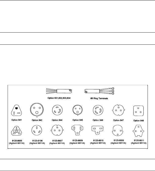
Installing the Power Cord
The power cord supplied with the ac source may or may not include a power plug at one end of the cord. Figure 2-2 shows the various power plugs. Terminating connections are attached to the other end of the cord.
Figure 2-2. Power Cord Plug Configurations
WARNING: Installation of the power cord must be done by a qualified and licensed electrician and must be in accordance with local electrical codes.
See Figure 2-3 while performing the following procedure.
a.If they are not already in place, position the strain relief connector (9), safety cover (5), rubber boot (8) and connector nut (7) on the power cord (6).
b.Secure the ground wire (2) to the chassis earth ground stud.
c.Connect the neutral wire (1) to the N power input terminal.
d.Connect the line (3) to the L1 power input terminal.
e.Position the safety cover over the power input terminals and tighten the cover and strain relief connector screws.
23

2 - Installation
L1 L2(N)
1 |
|
|
1. GROUND CONNECTION (GRN/YEL OR GRN) |
|
|
2. LINE CONNECTION (BROWN OR BLACK) |
|
|
|
|
|
2 |
|
|
3. NEUTRAL CONNECTION (BLUE OR WHITE) |
|
|
|
|
6 |
7 |
8 |
4. POWER CORD |
3 |
|
|
5. CONNECTOR NUT |
|
|
6. RUBBER BOOT |
|
|
|
|
|
|
|
|
7. POWER SAFETY COVER |
4 |
|
|
8. STRAIN RELIEF CONNECTOR |
5
Figure 2-3. Connecting the Power Cord
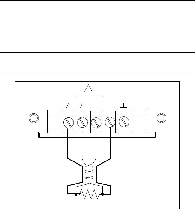
Output Connections
The power output terminal block has a floating output terminal connection and a floating neutral line for the return connection. A separate earth ground terminal is located on the extreme right of the terminal block.
!
SENSE
01 01 COM COM
300 VAC MAX TO
01 PHASE 1 OUTPUT CONNECTION COM PHASE RETURN CONNECTION
GROUND CONNECTION
Figure 2-4. Output Connections
24
Installation - 2
Wire Considerations
NOTE: To minimize the possibility of instability on the output, keep load leads as short as possible bundle or twist the leads tightly together to minimize inductance
Current Ratings
Fire Hazard To satisfy safety requirements, load wires must be large enough not to overheat when carrying the maximum short-circuit current of the ac source. If there is more than one load, then any pair of load wires must be capable of safely carrying the full-rated current of the ac source.
Table 2-1 lists the characteristics of AWG (American Wire Gage) copper wire.
Table 2-1. Ampacity and Resistance of Stranded Copper Conductors
AWG No. |
Ampacity1 |
Resistance2 |
AWG No. |
Ampacity1 |
Resistance2 |
|
|
(Ω/m) |
|
|
(Ω/m) |
14 |
25 |
0.0103 |
6 |
80 |
0.0016 |
12 |
30 |
0.0065 |
4 |
105 |
0.0010 |
10 |
40 |
0.0041 |
2 |
140 |
0.00064 |
8 |
60 |
0.0025 |
1/0 |
195 |
0.00040 |
|
|
NOTES: |
|
|
|
|
1. |
Ampacity is based on 30°C ambient temperature with conductor rated at 60°C. For ambient |
|||||
temperature other than 30°C, multiply the above ampacities by the following constants: |
|
|||||
|
Temp. (°C) |
Constant |
|
Temp. (°C) |
|
Temp. (°C) |
|
21-25 |
1.08 |
|
41-45 |
|
0.71 |
|
26-30 |
1.00 |
|
46-50 |
|
0.58 |
|
31-35 |
0.91 |
|
51-55 |
|
0.41 |
|
36-40 |
0.82 |
|
|
|
|
2. |
Resistance is nominal at 75 °C wire temperature. |
|
|
|
||
Voltage Drops
The load wires must also be large enough to avoid excessive voltage drops due to the impedance of the wires. In general, if the wires are heavy enough to carry the maximum short circuit current without overheating, excessive voltage drops will not be a problem. Refer to Table 2-1 to calculate the voltage drop for some commonly used AWG copper wire. If load regulation becomes a problem refer to the section "Remote Sense Connections".
Remote Sense Connections
Under normal operation, the ac source senses the output voltage at the output terminals on the back of the unit. External sense terminals are available on the back of the unit that allow the output voltages to be sensed at the load, compensating for impedance losses in the load wiring. As shown in the following figure:
25
2 - Installation
♦Connect the phase 1 (1) sense terminals to the side of the load that connects to the corresponding output terminal.
♦Connect the Neutral (COM) sense terminal connector to the neutral side of the load.
♦Twist and shield all signal wires to and from the sense connectors.
The sense leads are part of the ac source’s feedback path and must be kept at a low resistance in order to maintain optimal performance. Connect the sense leads carefully so that they do not become opencircuited.
CAUTION: If the sense leads are left unconnected or become open during operation, the ac source will regulate at the output terminals, but with a 40% increase in output voltage over the programmed limit. The meter circuit cannot read back this increase in output voltage when the sense lead is disconnected.
Set the ALC command to EXT (external) to enable remote sensing. The ALC command is located under the Voltage key as explained in Chapter 4. Set the ALC command to INT (internal) to disable remote sensing.
NOTE: If you are using external relays to connect and disconnect the load and sense connections, do NOT permit the sense connections to open when remote sensing is enabled. First disable remote sensing, then open the sense and load connections.
!
SENSE
01 01 COM COM
LOAD
Figure 2-5. Remote Sense Connections
26

Installation - 2
Remote Sensing and OVP Considerations
In remote sense applications, the voltage drop in the load leads subtracts from the available load voltage (see "Remote Sensing Capability" in appendix A). As the ac source increases its output to overcome this voltage drop, the sum of the programmed voltage and the load-lead drop may exceed the ac source’s maximum voltage rating. This may trip the OV protection circuit, which senses the voltage at the output terminals, not at the load. When using remote sensing, you must program the OVP trip voltage high enough to compensate for the voltage drop between the output terminals and the load.
NOTE: If the load causes the peak current limit circuit to become active, voltage transitions on the output may cause nuisance tripping of the OVP circuit.
Trigger Connections
The BNC trigger connectors on the rear panel let you apply trigger signals to the ac source as well as generate trigger signals from the ac source. The electrical characteristics of the trigger connectors are described in appendix A. More information on programming external triggers is found in Chapter 4 of the ac source Programming Guide.
Trigger IN Allows negative-going external trigger signals to trigger the ac source.
Trigger OUT Generates a negative-going pulse when the selected transient output has occurred.
Digital Connections
This connector, which is on the rear panel, is for connecting the fault and the inhibit signals. The fault (FLT) signal is also referred to as the DFI signal in the front panel and SCPI commands. The inhibit (INH) signal is also referred to as the RI signal in the front panel and SCPI commands.
The connector accepts wires sizes from AWG 22 to AWG 12. Disconnect the mating plug to make your wire connections. The electrical characteristics of the digital connectors are described in appendix A. More information on programming the digital connectors is found in Chapter 4 of the ac source Programming Guide.
NOTE: It is good engineering practice to twist and shield all signal wires to and from the digital connectors
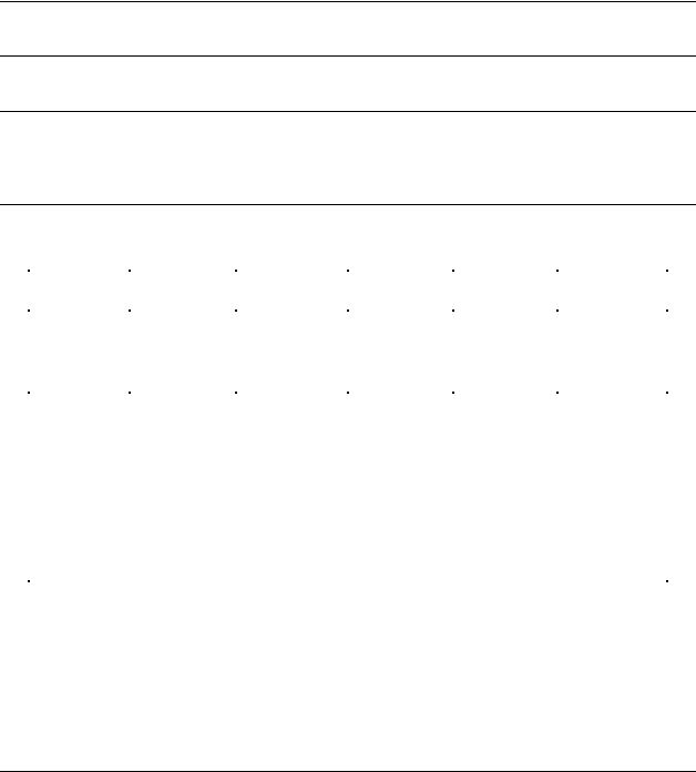
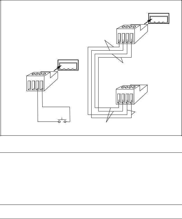
The following examples show how you can connect the FLT/INH circuits of the ac source.
In example A, the INH input connects to a switch that shorts pin + to pin whenever it is necessary to disable output of the unit. This activates the remote inhibit (RI) circuit, which turns off the ac output. The front panel Prot annunciator comes on and the RI bit is set in the Questionable Status Event register. To re-enable the unit, first open the connection between pins + and and then clear the protection circuit. This can be done either from the front panel or over the GPIB/RS-232.
27
2 - Installation
In example B, the FLT output of one unit is connected to the INH input of another unit. A fault condition in one of the units will disable all of them without intervention either by the controller or external circuitry. The controller can be made aware of the fault via a service request (SRQ) generated by the Questionable Status summary bit.
FLT INH
+ - + -I
. . . .
+ - + -I
NOTE: Connectors
are removable
FLT Output
FLT INH
+ - + -I
. . . . |
INH Input |
|
|
+ - + -I |
|
|
+ - + -I |
INH Input |
INH Common |
|
|
Switch |
INH Input |
|
(Normally |
|
|
Open) |
|
|
|
FLT Output |
A) INH Example with One Unit |
B) FLT Example with Multiple Units |
|
Figure 2-6. FLT/INH Examples
Controller Connections
The ac source connects to a controller either through a GPIB or an RS-232 connector.
GPIB Connector
Each ac source has its own GPIB bus address. AC sources may be connected to the bus in series configuration, star configuration, or a combination of the two. You may connect from 1 to 15 ac sources to a controller GPIB interface.
NOTE: The ac source is shipped from the factory with its GPIB address set to 5. This address can be changed as described in Chapter 4 of this guide.
28
Loading...