


 Loading...
Agilent Technologies 5745A, 5744A, 5743A, 5742A, 5747A User Manual
...Agilent Technologies
System DC Power Supply
Series N5700
User’s Guide


 A
A

Legal Notices
© Agilent Technologies, Inc. 2004 - 2006
No part of this document may be photocopied, reproduced, or translated to another language without the prior agreement and written consent of Agilent Technologies, Inc. as governed by United States and international copyright laws.
Warranty
The material contained in this document is provided “as is,” and is subject to being changed, without notice, in future editions. Further, to the maximum extent permitted by applicable law, Agilent disclaims all warranties, either express or implied, with regard to this manual and any information contained herein, including but not limited to the implied warranties of merchantability and fitness for a particular purpose. Agilent shall not be liable for errors or for incidental or consequential damages in connection with the furnishing, use, or performance of this document or of any information contained herein. Should Agilent and the user have a separate written agreement with warranty terms covering the material in this document that conflict with these terms, the warranty terms in the separate agreement shall control.
Manual Editions
Manual Part Number: 5969-2917 Edition 5, May, 2006
Printed in Malaysia.
Reprints of this manual containing minor corrections and updates may have the same printing date. Revised editions are identified by a new printing date.
Waste Electrical and Electronic Equipment (WEEE) Directive 2002/96/EC
This product complies with the WEEE Directive 2002/96/EC) marketing requirement. The affixed product label (see below) indicates that you must not discard this electrical/electronic product in domestic household waste.
Product Category: With reference to the equipment types in the WEEE directive Annex 1, this product is classified as “Monitoring and Control instrumentation” product.
Do not dispose in domestic household waste.
To return unwanted products, contact our local Agilent office, or see www.agilent.com/environment/product for more information.
Certification
Agilent Technologies certifies that this product met its published specifications at time of shipment from the factory.
Agilent Technologies further certifies that its calibration measurements are traceable to the United States National Institute of Standards and Technology, to the extent allowed by the Institute's calibration facility, and to the calibration facilities of other International Standards Organization members.
Exclusive Remedies
THE REMEDIES PROVIDED HEREIN ARE THE CUSTOMER'S SOLE AND EXCLUSIVE REMEDIES. AGILENT TECHNOLOGIES SHALL NOT BE LIABLE FOR ANY DIRECT, INDIRECT, SPECIAL, INCIDENTAL, OR CONSEQUENTIAL DAMAGES, WHETHER BASED ON CONTRACT, TORT, OR ANY OTHER LEGAL THEORY.
Assistance
This product comes with the standard product warranty. Warranty options, extended support contacts, product maintenance agreements and customer assistance agreements are also available. Contact your nearest Agilent Technologies Sales and Service office for further information on Agilent Technologies' full line of Support Programs.
Technologies Licenses
The hardware and or software described in this document are furnished under a license and may be used or copied only in accordance with the terms of such license.
Restricted Rights Legend
Software and technical data rights granted to the federal government include only those rights customarily provided to end user customers. Agilent provides this customary commercial license in Software and technical data pursuant to FAR 12.211 (Technical Data) and 12.212 (Computer Software) and, for the Department of Defense, DFARS 252.2277015 (Technical Data – Commercial Items) and DFARS 227.7202-3 (Rights in Commercial Computer Software or Computer Software Documentation).
Trademarks
Microsoft and Windows are U.S. registered trademarks of Microsoft Corporation.
2 |
Series N5700 User’s Guide |
Safety Notices
The following general safety precautions must be observed during all phases of operation of this instrument. Failure to comply with these precautions or with specific warnings or instructions elsewhere in this manual violates safety standards of design, manufacture, and intended use of the instrument. Agilent Technologies assumes no liability for the customer's failure to comply with these requirements.
General
Do not use this product in any manner not specified by the manufacturer. The protective features of this product may be impaired if it is used in a manner not specified in the operation instructions.
Before Applying Power
Verify that all safety precautions are taken. Make all connections to the unit before applying power. Note the instrument's external markings described under "Safety Symbols"
Ground the Instrument
This product is a Safety Class 1 instrument (provided with a protective earth terminal). To minimize shock hazard, the instrument chassis and cover must be connected to an electrical ground. The instrument must be connected to the ac power mains through a grounded power cable, with the ground wire firmly connected to an electrical ground (safety ground) at the power outlet. Any interruption of the protective (grounding) conductor or disconnection of the protective earth terminal will cause a potential shock hazard that could result in personal injury.
Fuses
The instrument contains an internal fuse, which is not customer accessible.
Do Not Operate in an Explosive Atmosphere
Do not operate the instrument in the presence of flammable gases or fumes.
Do Not Remove the Instrument Cover
Only qualified, service-trained personnel who are aware of the hazards involved should remove instrument covers. Always disconnect the power cable and any external circuits before removing the instrument cover.
Do Not Modify the Instrument
Do not install substitute parts or perform any unauthorized modification to the product. Return the product to an Agilent Sales and Service Office for service and repair to ensure that safety features are maintained.
In Case of Damage
Instruments that appear damaged or defective should be made inoperative and secured against unintended operation until they can be repaired by qualified service personnel
CAUTION
A CAUTION notice denotes a hazard. It calls attention to an operating procedure, practice, or the like that, if not correctly performed or adhered to, could result in damage to the product or loss of important data. Do not proceed beyond a CAUTION notice until the indicated conditions are fully understood and met.
WARNING
A WARNING notice denotes a hazard. It calls attention to an operating procedure, practice, or the like that, if not correctly performed or adhered to, could result in personal injury or death. Do not proceed beyond a WARNING notice until the indicated conditions are fully understood and met.
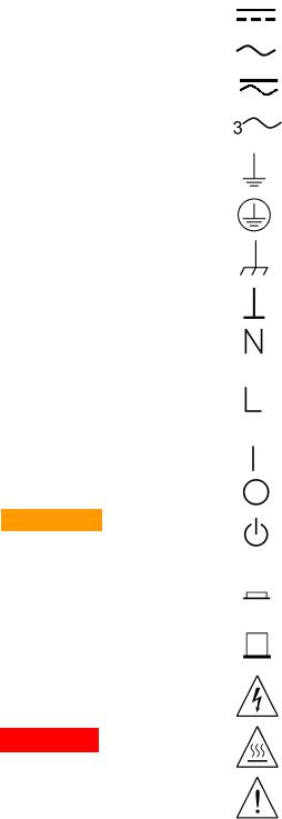
Safety Symbols
Direct current
Alternating current
Both direct and alternating current
Three phase alternating current
Earth (ground) terminal
Protective earth ground terminal.
Frame or chassis terminal
Terminal is at earth potential.
Neutral conductor on permanently installed equipment
Line conductor on permanently installed equipment.
On supply
Off supply
Standby supply. Unit is not completely disconnected from ac mains when switch is off
In position of a bi-stable push switch
Out position of a bi-stable push switch
Caution, risk of electric shock
Caution, hot surface
Caution, refer to accompanying documents
Series N5700 User’s Guide |
3 |

In this Book
NOTE
This User’s Manual contains the operating instructions, installation instructions, and specifications of the Agilent Technologies Series N5700 750W and 1500W System DC Power Supplies. Specific chapters in this manual contain the following information:
Quick Reference – Chapter 1 is a quick reference section that helps you quickly become familiar with your Agilent N5700 power supply.
Installation – Chapter 2 describes how to install your power supply. It describes how to connect various loads to the output. It discusses remote sensing as well as parallel and series operation.
Operating the Power Supply Locally – Chapter 3 describes how to operate the power supply from the front panel and from the analog connector on the rear panel. It also includes a turn-on check-out procedure to verify the unit is operating properly.
Operating the Power Supply Remotely – Chapter 4 describes how to configure the remote interfaces. It also gives a brief overview of the SCPI command structure and basic programming concepts.
Language Reference – Chapter 5 describes all of the SCPI programming commands.
Programming Examples – Chapter 6 provides Visual BASIC example programs that illustrate some common applications.
Specifications – Appendix A describes specifications and supplemental characteristics.
Verification and Calibration Procedures – Appendix B explains the verification and calibration procedures.
Service – Appendix C describes what to do if your unit requires service.
Compatibility – Appendix D documents the compatibility commands of the Agilent 603xA power supplies that are supported by the Agilent N5700 power supplies.
You can contact Agilent Technologies at one of the following telephone numbers for warranty, service, or technical support information.
In the United States: (800) 829-4444 In Europe: 31 20 547 2111
In Japan: 0120-421-345
Or use our Web link for information on contacting Agilent in your country or specific location: www.agilent.com/find/assist
Or contact your Agilent Technologies Representative.
The web contains the most up to date version of the manual. Go to http://www.agilent.com/find/N5700 to get the latest version of the manual.
4 |
Series N5700 User’s Guide |

Contents
1 Quick Reference |
|
|
|
The Agilent N5700 DC Power Supplies – At a Glance |
................................. 8 |
|
The Front Panel - At a Glance......................................................................... |
10 |
|
The Rear Panel – At a Glance......................................................................... |
12 |
2 |
Installation |
|
|
General Information.......................................................................................... |
16 |
|
Inspecting the Unit ........................................................................................... |
17 |
|
Installing the Unit.............................................................................................. |
17 |
|
Connecting the Line Cord ................................................................................ |
19 |
|
Connecting the Load......................................................................................... |
21 |
|
Output Voltage Sensing ................................................................................... |
24 |
|
Load Considerations ......................................................................................... |
26 |
|
Parallel Connections......................................................................................... |
28 |
|
Series Connections........................................................................................... |
30 |
|
J1 Connector Connections .............................................................................. |
32 |
3 |
Operating the Power Supply Locally |
|
|
Turn-On Check-Out ........................................................................................... |
34 |
|
Normal Operation.............................................................................................. |
36 |
|
Protection Functions ........................................................................................ |
37 |
|
Output On/Off Controls.................................................................................... |
40 |
|
Analog Programming of Output Voltage and Current................................. |
42 |
4 Operating the Power Supply Remotely |
|
|
|
Connecting to the Interfaces .......................................................................... |
48 |
|
SCPI Commands – an Introduction................................................................ |
58 |
5 Language Reference |
|
|
|
SCPI Command Summary................................................................................ |
64 |
|
Calibration Commands ..................................................................................... |
66 |
|
Measure Commands......................................................................................... |
67 |
|
Output Commands ............................................................................................ |
68 |
|
Source Commands............................................................................................ |
69 |
|
Status Commands............................................................................................. |
71 |
|
System Commands ........................................................................................... |
77 |
|
Trigger Commands............................................................................................ |
79 |
Series N5700 User’s Guide |
5 |
6 Programming Examples |
|
|
|
Output Programming Example........................................................................ |
82 |
|
Trigger Programming Example........................................................................ |
84 |
Appendix A |
Specifications |
|
|
Performance Specifications ............................................................................ |
88 |
|
Supplemental Characteristics ......................................................................... |
89 |
|
Outline Diagram................................................................................................. |
91 |
Appendix B |
Verification and Calibration |
|
|
Verification ......................................................................................................... |
94 |
|
Calibration ........................................................................................................ |
113 |
Appendix C Service |
|
|
|
Types of Service Available............................................................................. |
116 |
|
Repackaging for Shipment............................................................................. |
116 |
|
Operating Checklist......................................................................................... |
116 |
|
Error Messages ............................................................................................... |
118 |
Appendix D |
Compatibility |
|
|
Differences – In General................................................................................ |
124 |
|
Compatibility Command Summary ............................................................... |
125 |
Index ........................................................................................................................................................... |
|
127 |
6 |
Series N5700 User’s Guide |

1
Quick Reference
The Agilent N5700 DC Power Supplies – At a Glance |
................................. 8 |
The Front Panel - At a Glance......................................................................... |
10 |
The Rear Panel – At a Glance......................................................................... |
12 |
This chapter concisely describes the Agilent Technologies Series
N5700 Power Supplies.
This chapter is not meant to describe every operating feature in detail. It is simply a quick reference guide to quickly become familiar with the essential components of the power supply. It can also be used as a memory jogger for experienced users to quickly find a front/rear panel function.
A quick reference programming command chart is included in the beginning of chapter 5.
Series N5700 User’s Guide |
7 |
1 Quick Reference
The Agilent N5700 DC Power Supplies – At a Glance
The Agilent Technologies Series N5700 System DC Power Supplies are general-purpose, 1U (rack unit) high, switching power supplies that are available with a wide variety of output voltage and current ratings.
These power supplies are power-factor corrected and operate from a worldwide AC voltage range. Output voltage and current are continuously displayed and LED indicators show the complete operating status of the power supply.
The front panel controls allow the user to set the output parameters, over-voltage, under-voltage, and over-current protection levels, and preview the settings.
The rear panel includes the necessary connectors to control and monitor the power supply operation by analog signals or by the builtin remote communication interfaces.
Output Features
•Constant voltage/constant current with automatic crossover.
•High-resolution voltage and current front panel controls.
•Accurate voltage and current readback.
•Independent edge-triggered external shut-off, and leveltriggered external enable/disable.
•Parallel master/slave operation with active current sharing.
•Remote sensing to compensate for voltage drop in load leads.
•Analog output programming and monitoring.
System Features
•Built-in GBIB/LAN/USB interface.
•A built-in Web server that lets you control the instrument directly from an internet browser on your computer.
•Zero-gap stacking - no ventilation holes at the top and bottom surface of the power supply.
•Universal input voltage with active power factor correction.
•Fan speed control for low noise and extended fan life.
8 |
Series N5700 User’s Guide |

Quick Reference 1
Programmable Functions
•Output voltage and current setting.
•Output voltage and current measurement.
•Output voltage and current trigger setting.
•Output On/Off control.
•Over-current protection setting.
•Over-voltage protection setting and readback.
•Under-voltage limit setting and readback.
•Start-up mode (either last setting or reset mode)
•Status register setting and readback.
•Bus trigger
•Calibration
Model Ratings
Model |
Voltage |
Current |
Model |
Voltage |
Current |
||||
|
Range |
Range |
|
Range |
Range |
||||
|
|
|
|
|
|
|
|
|
|
N5741A |
0 |
– 6V |
0 |
– 100A |
N5761A |
0 |
– 6V |
0 |
– 180A |
N5742A |
0 |
– 8V |
0 |
– 90A |
N5762A |
0 |
– 8V |
0 |
– 165A |
N5743A |
0 |
– 12.5V |
0 |
– 60A |
N5763A |
0 |
– 12.5V |
0 |
– 120A |
N5744A |
0 |
– 20V |
0 |
– 38A |
N5764A |
0 |
– 20V |
0 |
– 76A |
N5745A |
0 |
– 30V |
0 |
– 25A |
N5765A |
0 |
– 30V |
0 |
– 50A |
N5746A |
0 |
– 40V |
0 |
– 19A |
N5766A |
0 |
– 40V |
0 |
– 38A |
N5747A |
0 |
– 60V |
0 |
– 12.5A |
N5767A |
0 |
– 60V |
0 |
– 25A |
N5748A |
0 |
– 80V |
0 |
– 9.5A |
N5768A |
0 |
– 80V |
0 |
– 19A |
N5749A |
0 |
– 100V |
0 |
– 7.5A |
N5769A |
0 |
– 100V |
0 |
– 15A |
N5750A |
0 |
– 150V |
0 |
– 5A |
N5770A |
0 |
– 150V |
0 |
– 10A |
N5751A |
0 |
– 300V |
0 |
– 2.5A |
N5771A |
0 |
– 300V |
0 |
– 5A |
N5752A |
0 |
– 600V |
0 |
– 1.3A |
N5772A |
0 |
– 600V |
0 |
– 2.5A |
Minimum output voltage is ≤ 0.2% of the rated output voltage.
Minimum output current is ≤ 0.4% of the rated output current.
Series N5700 User’s Guide |
9 |
1 Quick Reference
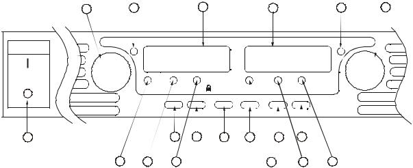
The Front Panel - At a Glance
1 2 3 4 5 6
VOLTAGE |
DC VOLTS |
DC AMPS |
CURRENT |
CV |
|
|
CC |
|
FINE LIMIT/ |
OVP |
|
PROT |
UVL OCP/488 LAN OUT ON |
|
|
POWER |
|
|
|
|
|
|
|
|
|
|
19 |
|
|
16 |
14 |
13 |
11 |
9 |
7 |
|
|
|
18 |
17 |
15 |
|
|
|
12 |
10 |
8 |
1 |
– VOLTAGE knob |
Voltage function: Adjusts the output voltage, the over-voltage protection level, and the |
||||||||
|
|
under-voltage limit. If over-voltage protection or under-voltage limits have been set, |
||||||||
|
|
you cannot program the output voltage outside those limits. |
|
|||||||
|
|
GPIB address: Selects the GPIB address when OCP/488 is pressed and held. |
||||||||
2 |
– CV indicator |
When lit, indicates that the unit is operating in constant voltage mode – with the |
||||||||
|
|
output voltage being held constant. |
|
|
|
|
||||
3 |
– DC VOLTS display |
LED display that normally displays the voltage measured at the sense terminals. |
||||||||
|
|
When LIMIT is pressed, the display indicates the programmed voltage setting. |
||||||||
|
|
When OVP/UVL is pressed, the display indicates either the OVP or UVL setting. |
||||||||
|
|
When OCP/488 is pressed and held, the display indicates the GPIB address. |
||||||||
|
|
When LAN is pressed and held, the display indicates the IP and Ethernet address. |
||||||||
4 |
– DC AMPS display |
LED display that normally displays the current measured at the output terminals. |
||||||||
|
|
When LIMIT is pressed, the display indicates the programmed current setting. |
||||||||
|
|
When LAN is pressed and held, the display indicates the IP and Ethernet address. |
||||||||
5 |
– CC indicator |
When lit, indicates that the unit is operating in constant current mode – with the |
||||||||
|
|
output current being held constant. |
|
|
|
|
||||
6 |
– CURRENT knob |
Adjusts the output current. |
|
|
|
|
|
|||
7 |
– OUT ON button |
Output function: Press OUT ON to turn the output on or off. Press OUT ON to reset |
||||||||
|
|
and turn the output on after an OVP or OCP event has occurred. |
|
|||||||
|
|
Start-up function: Selects between Safe-Start and Auto-Restart modes. Press and hold |
||||||||
|
|
the OUT ON button to toggle between Safe-Start and Auto-Restart. The display cycles |
||||||||
|
|
between SAF and AU7. Releasing the OUT ON button while one of the modes is |
||||||||
|
|
displayed selects that mode. |
|
|
|
|
|
|||
8 |
– OUT ON indicator |
When lit, indicates that the output is enabled or on. |
|
|
||||||
10 |
Series N5700 User’s Guide |
|
|
Quick Reference 1 |
9 – LAN button |
View address: Press LAN to view the IP and Ethernet address. The display first scrolls |
|
|
|
through the four segments of the IP address, followed by the six segments of the |
|
|
Ethernet (EA) address. Press any key to turn the address display off. |
|
|
Reset address: Press and hold the LAN button for three seconds. Pressing the LAN |
|
|
button again while the message “LAn rES” is displayed resets the LAN configuration |
|
|
to the factory-shipped settings (see chapter 4 for settings). If the key is not pressed |
|
|
again, the display returns to normal and the configuration is not changed. |
10 |
– LAN indicator |
When lit, indicates that the LAN has been configured and is operating normally. |
|
|
When blinking, identifies the unit for which the indicator has been set to blink by the |
|
|
unit’s Web home page. |
11 |
– OCP/488 button |
Enable OCP: Press OCP/488 to turn over-current protection on. Press OCP/488 again |
|
|
to turn over-current protection off. |
|
|
Reset OCP: When an over-current protection event occurs, press the OUT ON button |
|
|
to enable the output and re-arm over-current protection. |
|
|
GPIB address: Press and hold the OCP/488 button for three seconds. This lets you set |
|
|
the GPIB address with the Voltage knob. |
12 |
– OCP indicator |
When lit, indicates that over-current protection is enabled or on. |
13 |
– OVP/UVL button |
OVP function: Press OVP/UVL once to set the over-voltage protection level with the |
|
|
Voltage knob (the display shows OUP). You cannot set the over-voltage protection |
|
|
lower than about 5% above the present output voltage setting. |
|
|
UVL function: Press OVP/UVL twice to set the under-voltage programming limit with |
|
|
the Voltage knob (the display shows UUL). You cannot set the under-voltage |
|
|
protection higher than about 5% below the present output voltage setting. |
14 |
– LIMIT button |
Limit function: Press LIMIT to display the output voltage and current limit. For five |
|
|
seconds the display shows the settings and then it returns to show the actual output |
|
|
voltage and current. |
|
|
Lock function: Press and hold the LIMIT button to toggle between Locked front panel |
|
|
and Unlocked front panel. The display will cycle between LFP and UFP. Releasing the |
|
|
LIMIT button while one of the modes is displayed selects that mode. If the display |
|
|
indicates rLFP, the front panel has been locked by a remote programming command. |
15 |
– LIMIT indicator |
When lit, indicates that the LIMIT button is pressed. |
16 |
– FINE button |
Selects Fine or Coarse adjustment control. In Fine mode, the Voltage and Current |
|
|
knobs operate with high resolution; in Coarse mode, with lower resolution |
|
|
(approximately six turns). |
17 |
– FINE indicator |
When lit, indicates that the unit is in Fine adjustment mode. |
18 |
– PROT indicator |
When blinking, indicates that a fault has occurred. |
|
|
OVP, OCP, OTP, Enable fail, and AC fail detection will cause the PROT indicator to |
|
|
blink. The PROT indicator may blink and the display indicate AC for a few seconds after |
|
|
the unit is turned off because of residual energy inside the unit. |
19 |
– POWER switch |
Turns the power supply on or off. |
Series N5700 User’s Guide |
11 |

1 Quick Reference
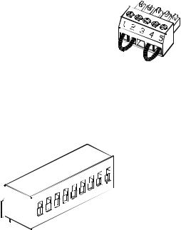
The Rear Panel – At a Glance
J2 SW1 |
ON |
+S+LS NC -LC-S 1 2 3 4 5 6 7 8 9 OFF
7 6
|
|
8 |
|
|
9 |
|
10/100 Ethernet |
! |
|
! |
|
|
LINK |
TX |
|
||
|
+V |
-V |
|
||
|
|
|
|
||
GPIB |
J1 |
|
|
|
|
|
|
|
|
|
|
ANALOG PROGRAMMING |
NOT ACTIVE |
|
|
AC INPUT |
|
|
|
|
80V - 600V |
|
750W |
|
|
|
3 |
2 |
1 |
|
5 |
4 |
|
|
|
|
|
|
6V - 60V |
|
1500W |
1 |
– AC input connector |
Wire clamp connector for 1500W output models. |
|
|
IEC connector for 750W output models. |
2 |
– DC output connector |
Wire clamp connector for 80V to 600V models. |
|
|
Bus bars for 6V to 60V models. |
3 |
– USB connector |
Connector for connecting to a USB interface. See chapter 4 for setup. |
4 |
– LAN connector |
Connector for connecting to a LAN interface. LINK LED indicates link integrity. |
|
|
TX LED indicates LAN activity. See chapter 4 for LAN setup. |
5 |
– Analog Programming |
Connector for the analog interface. Includes output voltage and current limit |
|
connector |
programming and monitoring signals, Shut-Off control (electrical signal), |
|
|
Enable/Disable control (dry-contact), power supply ok (Power Supply OK) signal |
|
|
and operation mode (CV/CC) signal. (See next page for details) |
6 |
– SW1 setup switch |
Nine-position switch for selecting remote programming and monitoring modes |
|
|
for Output Voltage, Current Limit and other control functions. (See next page for |
|
|
details) |
7 |
– Remote Sense connector |
Connector for making remote sensing connections for regulating the load |
|
|
voltage and compensating for wiring voltage drop. (See next page for details) |
8 – GPIB connector
9 – Ground screw
WARNING
Connector for connecting to a GPIB interface. See chapter 4 for setup. M4x8 screws for making chassis ground connections
SHOCK HAZARD The power cord provides a chassis ground through a third conductor. Be certain that your power outlet is of the three-conductor type with the correct pin connected to earth ground
12 |
Series N5700 User’s Guide |
Quick Reference 1
J2 Sense Connector
1 – Remote sense (+)
2 – Local sense (+)
3 – Not used
4 – Local sense (–)
5 – Remote sense (–)
The factory-shipped configuration is shown in the figure.
SW1 Setup Switch
1 – Output voltage, voltage programming
2 – Output current, voltage programming
3 – Programming range (voltage/resistance)
4 – Voltage and Current monitoring range
5– Shut-Off Logic Select
6– Not Used
7– Output voltage, resistive programming
8– Output current, resistive programming
9– Enable/Disable control
|
|
|
|
|
6 |
7 |
8 |
9 |
|
|
|
4 |
5 |
|
|
||
1 |
2 |
3 |
|
|
|
|
The factory-shipped setting is Down for all switches.
Down: The output voltage is programmed by the front panel.
Up: The output voltage is programmed by the external voltage signal.
Down: The output current is programmed by the front panel.
Up: The output current is programmed by the external voltage signal.
Down: The remote programming range is: 0 – 5V / 0 – 5KΩ. Up: The remote programming range is: 0 – 10V / 0 – 10KΩ.
Down: The remote monitoring range is: 0 – 5V. Up: The remote monitoring range is: 0 – 10V.
Down: OUT OFF = Low (0 – |
0.6V) or short; |
OUT ON = High (2V – 15V) or open. |
Up: OUT OFF = High (2V |
– 15V) or open; |
OUT ON = Low (0 – 0.6V) or short. |
Down: The output voltage is programmed by the front panel.
Up: The output voltage is programmed by the external resistor.
Down: The output current is programmed by the front panel.
Up: The output current is programmed by the external resistor.
Down: The J1 Enable+/Enable– pins are not active. Up: The J1 Enable+/Enable– pins are active.
Series N5700 User’s Guide |
13 |
1 Quick Reference
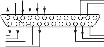
J1 Analog Programming Connector
Voltage Monitor |
|
|
|
|
|
|
|
|
Current Program |
|
|
|
|
|
|
|
|||
Common (-S) |
|
|
|
|
|
|
|
|
Voltage Program |
|
|
|
|
||||||
CV / CC |
|
|
|
|
|
|
|
|
Local / Analog |
|
|
|
|
|
|
|
|
13 |
12 |
11 |
10 |
9 |
8 |
7 |
6 |
5 |
4 |
3 |
2 |
1 |
25 |
24 |
23 |
22 |
21 |
20 |
19 |
18 |
17 |
16 |
15 |
14 |
|
Parallel |
|
|
|
|
|
|
|
|
|
|
|
|
Current Monitor |
|
|
|
|
|
|
|
|
|
|
|
|
Current Prog. Return |
|
|
|
|
|
|
|
|
|
|
|
|
Voltage Prog. Return |
|
|
|
|
|
|
|
|
|
|
|
|
Local / Analog State |
|
|
|
|
|
|
|
|
|
|
|
|
Chassis Common
Chassis Common
Enable +
Enable --
Shut Off
Power Supply OK
|
|
The factory-shipped default configuration is Local operation, which |
|
|
does not require connection to J1. |
Pin 1: |
Enable + |
Connect Pin 1 to Pin 14 to enable the output. Disconnect to disable the output. |
Pin 2, 3: |
Chassis Common |
Signal return for Pin 15 and Pin 16. Connected to chassis. |
Pin 4–7: |
Not Used |
No connection |
Pin 8: |
Local/Analog |
Input for selecting between front panel or analog programming of the output. |
Pin 9: |
Voltage Program |
Input for voltage or resistance programming of the output voltage. |
Pin 10: |
Current Program |
Input for voltage or resistance programming of the output current. |
Pin 11: |
Voltage Monitor |
Output for monitoring the output voltage. |
Pin 12: |
Common |
Signal return for Pin 8, Pin11, Pin 13, and Pin 24. Connected internally to –S. |
Pin 13: |
CV/CC |
Output for constant voltage/constant current mode indication. |
Pin 14: |
Enable – |
Connect Pin 14 to Pin 1 to enable the output. Disconnect to disable the output. |
Pin 15: |
Shut Off |
Input for Shut-Off control of the output. Referenced to Chassis Common. |
Pin 16: |
Power Supply OK |
Output to indicate the power supply status. Referenced to Chassis Common. |
Pin 17–20: |
Not Used |
No connection |
Pin 21: |
Local/Analog State |
Output for indication of local or analog programming mode. |
Pin 22: |
Voltage Prog. Return |
Signal return for Pin 9. Connected internally to –S. |
Pin 23: |
Current Prog. Return |
Signal return for Pin 10. Connected internally to –S. |
Pin 24: |
Current Monitor |
Output for monitoring the output current. |
Pin 25: |
Parallel |
Output for current balancing in parallel operation. |
14 |
Series N5700 User’s Guide |

2 Installation
General Information.......................................................................................... |
16 |
Inspecting the Unit ........................................................................................... |
17 |
Installing the Unit.............................................................................................. |
17 |
Connecting the Line Cord ................................................................................ |
19 |
Connecting the Load......................................................................................... |
21 |
Output Voltage Sensing ................................................................................... |
24 |
Load Considerations......................................................................................... |
26 |
Parallel Connections......................................................................................... |
28 |
Series Connections........................................................................................... |
30 |
J1 Connector Connections .............................................................................. |
32 |
This chapter describes how to install your power supply. It discusses installation, rack mounting, and line cord connections.
This chapter also discusses how to connect your load to the output terminals. It discusses what you need to know about wire sizes and how to compensate for voltage drops in the load leads. It also discusses various loads configurations and how to connect units in series and parallel.
Before getting started, check the list under “Items Supplied” and verify that you have received these items with your instrument. If anything is missing, please contact your nearest Agilent Sales and Service Office.
Series N5700 User’s Guide |
15 |

2 Installation
General Information
Models
750 W Models |
1500 W Models |
|
|
N5741A – N5749A |
N5761A – N5769A |
N5750A – N5752A |
N5770A – N5772A |
|
|
Items Supplied
Item |
Description |
|
|
Power Cord |
A power cord appropriate for your location |
|
750W units are supplied with terminated power cords |
|
1500W units are supplied with unterminated power cords |
Strain relief assembly |
A strain relief assembly for unterminated power cords |
|
(only used for 1500W units) |
AC input cover |
A cover for the AC input on which the strain relief assembly |
|
is mounted (only used for 1500W units) |
Analog connector |
A DB25 subminiature connector plug for analog control |
|
connections |
Shield assembly |
A safety shield for the output terminal connections |
Hardware |
Nuts, washers, and bolts for connecting load leads to output |
|
bus bars (only used for 6V to 60V units) |
Documentation Set |
Contains User’s Guide with Product Reference CD-ROM |
Certificate of Calibration |
A certificate of calibration referenced to the serial number |
Automation-Ready |
E2094N - contains Agilent IO Libraries Suite |
CD-ROM |
|
Accessories
Item |
Description |
|
|
N5740A |
Rack-mount slide kit for installing in system II cabinets |
|
|
16 |
Series N5700 User’s Guide |
Installation 2
Inspecting the Unit
When you receive your power supply, inspect it for any obvious damage that may have occurred during shipment. If there is damage, notify the shipping carrier and nearest Agilent Sales and Service Office immediately. Refer to Appendix C for more information.
Until you have checked out the power supply, save the shipping carton and packing materials in case the unit has to be returned.
Installing the Unit
Safety Considerations
This power supply is a Safety Class 1 instrument, which means it has a protective earth terminal. That terminal must be connected to earth ground through power source equipped with a ground receptacle. Refer to the Safety Summary page at the beginning of this guide for general safety information. Before installation or operation, check the power supply and review this guide for safety warnings and instructions. Safety warnings for specific procedures are located at appropriate places throughout this Guide.
Environment
|
Do not operate the instrument in the presence of flammable gasses or fumes |
WARNING |
|
|
|
|
The environmental conditions, dimensions of the instrument, as well |
|
as an outline diagram are given in Appendix A. Basically, the |
|
instrument should only be operated indoors in a controlled |
|
environment. Do not operate the power supply in an area where the |
|
ambient temperature exceeds 40° C. |
|
Agilent N5700 power supplies generate magnetic fields, which may affect the |
NOTE |
|
|
operation of other instruments. If your equipment is susceptible to magnetic |
|
fields, do not position it adjacent to the power supply. |
|
|
Airflow
Fans cool the power supply by drawing air through the front and exhausting it out the back. The instrument must be installed in a location that allows sufficient space of at least 10 cm (4 in) at the front and back of the unit for adequate air circulation.
Series N5700 User’s Guide |
17 |
2 Installation
Rack Installation
|
Ensure that the screws used to attach the rack slide kit do not penetrate more |
CAUTION |
|
|
than 6 mm into the sides of the unit. |
|
Do not block the air intake at the front, or the exhaust at the rear of the unit. |
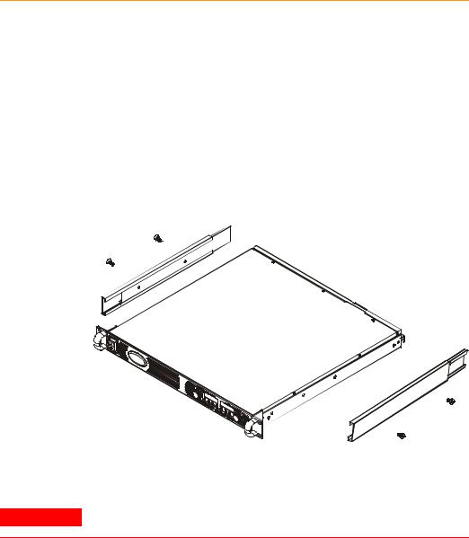
The Agilent N5700 power supplies can be mounted in a standard 19inch rack panel or cabinet. They are designed to fit in one rack unit (1U) of space. To install the power supply in a rack:
1.Use the front panel rack-mount brackets to install the power supply in the rack.
2.Use a support bracket to provide adequate support for the rear of the power supply.
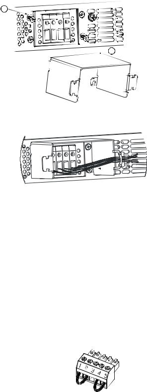
3.If using rack mount slides, use Agilent N5740A Rack-mount Slide Kit to install the unit in a standard 19-inch equipment rack. Refer to the following figure for assembly instructions. Use two #10-32 x 3/8 in (max.) screws at each side. To prevent internal damage, use the specified screw length only.
Cleaning
WARNING SHOCK HAZARD To prevent electric shock, unplug the unit before cleaning.
Use a dry cloth or one slightly dampened with water to clean the external case parts. Do not attempt to clean internally.
18 |
Series N5700 User’s Guide |

Installation 2
Connecting the Line Cord
|
SHOCK HAZARD The power cord provides a chassis ground through a third |
WARNING |
|
|
conductor. Be certain that your power outlet is of the three-conductor type |
|
with the correct pin connected to earth ground. |
|
FIRE HAZARD Use only the power cord that was supplied with your |
|
instrument. Using other types of power cords may cause overheating of the |
|
power cord, resulting in fire. |
|
|
|
The detachable power cord may be used as an emergency disconnecting |
NOTE |
|
|
device. Removing the power cord will disconnect ac input power to the unit. |
The AC input on the back of your unit is a universal AC input. It accepts line voltages in the range of 85 VAC to 265 VAC. The frequency range is 47 Hz to 63 Hz.
The input current requirement of 750W units is 10.5A @ 100 VAC nominal and 5A @ 200 VAC nominal. The current requirement of 1500W units is 21A @ 100 VAC nominal and 11A @ 200 VAC nominal.
Input Connections for 750W units
Connect the power cord to the IEC 320 connector on the rear of the unit. The IEC connector provides the safety ground connection when the AC cord is plugged into a grounded AC receptacle.
If the wrong power cord was shipped with your unit, contact your nearest Agilent Sales and Service Office.
Input Connections for 1500W units
|
Connection of this power supply to an AC power source should be made by a |
CAUTION |
|
|
qualified electrician or other qualified personnel. |
The AC input connector is a 3-terminal wire clamp located on the rear panel. Use suitable wires and tightening torque as follows:
•Wire diameter: 12 AWG or 10 AWG
•Tightening torque: 6.5 - 7.0 in-lb
Connect the cable to the AC input connector as follows:
•Strip the outside insulation of the AC cable approximately 10 cm (4 in). Trim the wires so that the ground wire is 10 mm (0.4 in) longer than the other wires. Strip 14 mm (0.55 in) at the end of each of the wires.
Series N5700 User’s Guide |
19 |
2 Installation
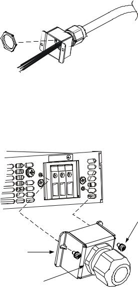
•Unscrew the base of the strain relief from the wire compression nut. Place the locknut inside the AC input cover with the flat side of the nut against the cover. Insert the base through the outside opening of the AC input cover. Screw the base securely onto the locknut from the outside (17 ft-lbs).
•Slide the wire compression nut over the AC cable. Insert the stripped wires through the strain relief base until the outer cable jacket is flush with the inside edge of the base. Place a wrench on the base to keep it from turning. Now tighten the compression nut to the base (14-16.2 ft-lbs) while holding the cable in place. Now the cable is securely fastened inside the strain relief. Refer to the following figure.
•Route the AC wires to the input connector terminals as required. To connect the wires, loosen the terminal screw, insert the stripped wire into the terminal, and tighten the screw securely to between 4.4–5.3 in-lbs.
•Route the wires inside the cover to prevent pinching. Fasten the cover to the unit using the M3 x 8mm pan head screws provided (4.8 in-lbs). Refer to the following figure for details.
L N
M3 x 8mm Pan Head Screws
(2 places)
Cover
Assembled
Strain Relief
20 |
Series N5700 User’s Guide |
|
|
Installation 2 |
Connecting the Load |
|
|
|
|
SHOCK HAZARD Turn off AC power before making rear panel connections. |
|
WARNING |
|
|
|
All wires and straps must be properly connected with screws securely |
|
|
tightened. |
As further explained in this section, the following factors should be considered when selecting wiring to connect the load to the power supply:
•Current carrying capacity of the wire
•Insulation rating of the wire should be at least equivalent to the maximum output voltage of the power supply
•Maximum wire length and voltage drop
•Noise and impedance effects of the load wiring
Wire Size
|
|
FIRE HAZARD To satisfy safety requirements, select a wire size heavy |
||||||
WARNING |
||||||||
|
|
enough not to overheat |
while carrying the power supply load current at the |
|||||
|
|
rated load, or the current that would flow in the event the load wires were |
||||||
|
|
shorted, whichever is greater. |
|
|
|
|
||
|
|
|
||||||
|
|
Along with conductor temperature, you must also consider voltage |
||||||
|
|
drop when selecting wire sizes. The following chart lists the |
|
|||||
|
|
resistance for various wire sizes and also the maximum lengths to |
||||||
|
|
limit the voltage drop to 1.0 volt for various currents. |
|
|||||
|
|
Although the power supply will compensate for up to 5V in each load |
||||||
|
|
wire, it is recommended to minimize the voltage drop to less than 1V |
||||||
|
|
to prevent excessive output power consumption from the power |
||||||
|
|
supply and poor dynamic response to load changes. |
|
|
||||
|
|
|
|
|
||||
|
|
Wire size |
Resistance |
Maximum length in feet to limit voltage to 1 V |
||||
|
|
AWG |
Ω/1000 foot |
for 5 A |
for 10 A |
for 20A |
for 50A |
for 150A |
|
|
14 |
2.526 |
80 |
40 |
20 |
8 |
2 |
|
12 |
1.589 |
120 |
60 |
30 |
12 |
3.4 |
|
|
10 |
0.9994 |
200 |
100 |
50 |
20 |
6 |
|
|
8 |
0.6285 |
320 |
160 |
80 |
32 |
10 |
|
|
6 |
0.3953 |
500 |
250 |
125 |
50 |
16 |
|
|
4 |
0.2486 |
800 |
400 |
200 |
80 |
26 |
|
|
2 |
0.1564 |
1200 |
600 |
300 |
125 |
40 |
|
|
|
0 |
0.0983 |
2000 |
1000 |
500 |
200 |
68 |
Series N5700 User’s Guide |
21 |
2 Installation
Cross |
|
|
|
|
|
|
section |
Resistance |
Maximum length in meters to limit voltage to 1 V |
||||
(mm2) |
Ω/kilometer |
for 5 A |
for 10 A |
for 20A |
for 50A |
for 150A |
2.5 |
8.21 |
24.0 |
12.0 |
6.0 |
2.4 |
0.8 |
4 |
5.09 |
39.2 |
18.6 |
9.8 |
4.0 |
1.4 |
6 |
3.39 |
59.0 |
29.4 |
14.8 |
5.8 |
2.0 |
10 |
1.95 |
102 |
51.2 |
25.6 |
10.2 |
3.4 |
16 |
1.24 |
160 |
80.0 |
40.0 |
16.0 |
5.4 |
25 |
0.795 |
250 |
125 |
62.0 |
25.2 |
8.4 |
35 |
0.565 |
354 |
177 |
88.0 |
35.4 |
11.8 |
Load Connections for 6V to 60V Models
|
SHOCK HAZARD Hazardous voltages may exist at the outputs and the load |
WARNING |
|
|
connections when using a power supply with a rated output greater than 40V. |
|
To protect personnel against accidental contact with hazardous voltages, |
|
ensure that the load and its connections have no accessible live parts. Ensure |
|
that the load wiring insulation rating is greater than or equal to the maximum |
|
output voltage of the power supply. |
|
|
|
Ensure that the load wiring mounting hardware does not short the output |
|
CAUTION |
||
|
terminals. Heavy connecting cables must have some form of strain relief to |
|
|
prevent loosening the connections or bending the bus-bars. |
|
|
|
|
|
All load wires should be properly terminated with wire terminals |
|
|
securely attached. Do not use unterminated wires for load |
|
|
connections at the power supply. The following figures illustrate how |
|
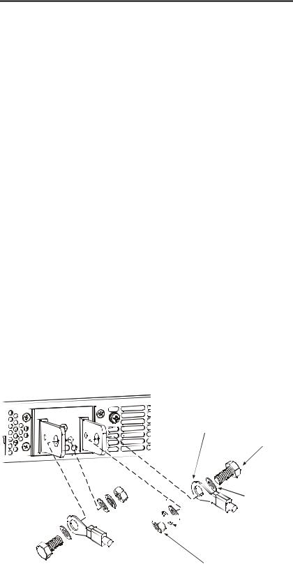
|
to connect the load wires to the power supply bus-bars as well as |
|
|
how to mount the bus-bar shield to the chassis. |
|
|
Wire terminal lug (2 places) |
|
|
M8x15 screw (2 places) |
|
Flat washer (2 places)


 Flat washer (2 places)
 Spring washer (2 places)
Hex Nut (2 places)
Screws tightening torque: 104-118 in-lb.
22 |
Series N5700 User’s Guide |
Installation 2
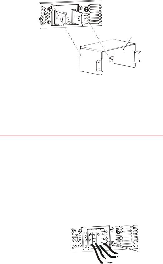
Install the shield after you have finished connecting the load wires.
Shield
Load Connections for 80V to 600V Models
|
SHOCK HAZARD Hazardous voltages may exist at the outputs and the load |
WARNING |
|
|
connections when using a power supply with a rated output greater than 40V. |
|
To protect personnel against accidental contact with hazardous voltages, |
|
ensure that the load and its connections have no accessible live parts. Ensure |
|
that the load wiring insulation rating is greater than or equal to the maximum |
|
output voltage of the power supply. |
The 80V to 600V models have a four-terminal wire clamp output connector. The two left terminals are the positive outputs and the two right terminals are the negative outputs. The connector specifications are as follows:
Wire Size: |
AWG 18 to AWG 10 |
Stripping Length: |
10 mm (0.39 in.) |
Torque: |
6.5 - 7 in-lb. |
The following instructions describe how to connect the load wires to the power supply:
•Strip wires back approximately 10 mm (0.39 in).
•Loosen the connector terminal screws and insert the stripped wires into the terminal. Tighten the terminal screw securely.
+V -V 


Positive Output (+)


Negative (-)
Output/Return


 Load wires
Series N5700 User’s Guide |
23 |
2 Installation
•Loosen the two chassis screws marked A halfway.
•Assemble the protective shield to the chassis and tighten the two screws to fix the shield to the chassis. Screw tightening torque: 4.8-5.3 in-lb
A
 A
A
•Tighten the wires to one of the shield sides using tie-wrap or equivalent. Refer to the following figure.
 Load
Load
wires
•Ensure that the wire length inside the shield is long enough to provide proper strain relief.
Output Voltage Sensing
|
SHOCK HAZARD There is a potential shock hazard at the sense connector |
|||
WARNING |
||||
|
when using a power supply with a rated output greater than 40V. Ensure that |
|||
|
the local sense and remote sense wiring insulation rating is greater than or |
|||
|
equal to the maximum output voltage of the power supply. Ensure that the |
|||
|
connections at the load end are shielded to prevent accidental contact with |
|||
|
hazardous voltages. |
|||
|
|
|
|
|
|
Local and remote sense connections are made at the J2 connector. |
|||
|
The connector has a removable plug that makes it easy for you to |
|||
|
make your wire connections. Refer to the following figure for the |
|||
|
terminal assignments. |
|||
|
1 |
Remote sense (+) |
||
|
2 |
Local sense (+) |
||
|
3 |
Not connected |
||
|
4 |
Local sense (-) |
||
|
5 |
Remote sense (-) |
|
|
|
|
|||
|
|
|||
24 |
Series N5700 User’s Guide |
Installation 2
The J2 connector plug specifications are as follows:
Plug Type: |
MC 1.5/5-ST-3.81, Phoenix |
Wire Size: |
AWG 28 to AWG 16 |
Stripping Length: |
7 mm (0.28 in.) |
Torque: |
0.22 – 0.25 Nm (1.95 – 2.21 in-lb.) |
Local Sensing
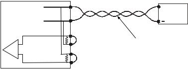
The power supply is shipped with the rear panel J2 sense connector wired for local sensing of the output voltage. With local sensing, the output voltage regulation is made at the output terminals. This method does not compensate for voltage drop on the load wires, therefore it is recommended only for low load current applications or where the load regulation is less critical. The following figure illustrates the internal connections of the J2 connector.
Power |
|
+V |
+ |
|
|
|
Load |
||
Supply |
-V |
|||
|
||||
|
|
-Rem.sense |
|
|
Error |
-Local sense |
Load lines, twisted |
||
Amp. |
+Local sense |
pair, shortest length |
||
|
possible. |
|||
+Rem.sense
|
If the power supply is operated without the local sense jumpers or without the |
|
NOTE |
||
remote sense lines connected, it will continue to work, but the output voltage |
||
|
||
|
regulation will be degraded. Also, the OVP circuit may activate and shut down |
|
|
the power supply. Note that the internal wiring between +V and + local sense |
|
|
and between –V and – local sense will fail if load current flows through it. |
|
|
|
Remote Sensing
Use remote sensing in applications where load regulation at the load is critical. Remote sensing allows the power supply to automatically compensate for the voltage drop in the load leads. Refer to Appendix A for the maximum allowable voltage drop on the load wires.
Remote sensing is especially useful in constant voltage mode with load impedances that vary or have significant lead resistance. It has no effect in constant current mode. Because sensing is independent of other power supply functions it can be used regardless of how the power supply is programmed. With remote sensing, voltage readback monitors the load voltage at the remote sense points.
Use twisted or shielded wires to minimize noise pick-up. If shielded wires are used, the shield should be connected to the ground at one point, either at the power supply chassis or the load ground. The optimal point for the shield ground should be determined by experimentation.
Series N5700 User’s Guide |
25 |
2 Installation
NOTE
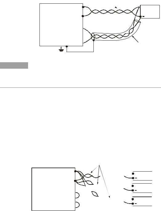
To configure the power supply for remote sensing:
•Turn off the power supply.
•Remove the local sense jumpers from the J2 connector.
•Connect the negative sense lead to terminal 5 (-S) and the positive sense lead to terminal 1 (+S). Make sure that the connector plug is securely inserted into the connector body.
•Turn on the power supply.
Load lines. Twisted pair shortest length possible.
|
+V |
|
Power |
-V |
|
Supply |
||
|
-Rem.sense  -Local sense
  +Local sense
  +Rem.sense
 +
+
Load
Sense lines. Twisted pair or shielded wires.
If the power supply is operated with remote sensing and either the positive or negative load wire is not connected, an internal protection circuit will activate and shut down the power supply. To resume operation, turn the power supply off, connect the open load wire, and turn on the power supply.
Load Considerations
Multiple Loads
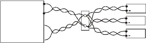
The following figure shows multiple loads connected to one power supply. Each load should be connected to the power supply’s output terminals using separate pairs of wires. It is recommended that each pair of wires will be as short as possible and twisted or shielded to minimize noise pick-up and radiation. The sense wires should be connected to the power supply output terminals or to the load with the most critical load regulation requirement.
|
+V |
|
Power |
-V |
|
Supply |
||
|
-Rem.sense  -Local sense
  +Local sense
  +Rem.sense
Load lines, twisted pair, shortest length possible.


 + Load#1


 + Load#2


 + Load#3
26 |
Series N5700 User’s Guide |
Installation 2
If remotely located distribution terminals are used, as shown in the following figure, the power supply output terminals should be connected to the remote distribution terminals by a pair of twisted and/or shielded wires. Connect each load to the distribution terminals separately. Remote voltage sensing is recommended under these circumstances. Sense either at the remote distribution terminals or, if one load is more sensitive than the others, directly at the critical load.
|
+V |
|
Power |
-V |
|
Supply |
||
|
-Rem.sense  -Local sense
  +Local sense
  +Rem.sense
Distribution terminal |
+ Load#1 |
+V |
|
|
+ Load#2 |
-V |
+ Load#3 |
Output Noise and Impedance Effects
To minimize the noise pickup or radiation, the load wires and remote sense wires should be twisted-pairs to the shortest possible length. Shielding of sense leads may be necessary in high noise environments. Where shielding is used, connect the shield to the chassis via a rear panel ground screw. Even if noise is not a concern, the load and remote sense wires should be twisted-pairs to reduce coupling, which might impact the stability of power supply. The sense leads should be separated from the power leads.
Twisting the load wires reduces the parasitic inductance of the cable, which could produce high frequency voltage spikes at the load and the output because of current variation in the load itself.
The impedance introduced between the power supply output and the load could make the ripple and noise at the load worse than the noise at the power supply rear panel output. Additional filtering with bypass capacitors at the load terminals may be required to bypass the high frequency load current.
Inductive Loads
Inductive loads can produce voltage spikes that may be harmful to the power supply. A diode should be connected across the output. The diode voltage and current rating should be greater than the power supply maximum output voltage and current rating. Connect the cathode to the positive output and the anode to the negative output of the power supply.
Where positive load transients such as back EMF from a motor may occur, connect a surge suppressor across the output to protect the power supply. The breakdown voltage rating of the suppressor must be approximately 10% higher than the maximum output voltage of the power supply.
Series N5700 User’s Guide |
27 |
2 Installation
Grounding the Output
|
The output of the power supply is isolated from earth ground. Either |
|
positive or negative voltages can be obtained from the output by |
|
grounding (or "commoning") one of the output terminals. Always use |
|
two wires to connect the load to the output regardless of where or |
|
how the system is grounded. |
|
To avoid noise problems caused by common-mode current flowing |
|
from the load to ground, it is recommended to ground the output |
|
terminal as close as possible to the power supply chassis ground. |
|
SHOCK HAZARD For models up to 60VDC rated output, no point shall be more |
WARNING |
|
|
than +/-60VDC above/below chassis ground. For models > 60VDC rated |
|
output, no point shall be more than +/-600VDC above/below chassis ground. |
|
There is also a potential shock hazard at the IEEE/LAN/USB ports when |
|
using power supplies with rated or combined voltages > 400VDC with the |
|
positive output of the power supplies grounded. Do not connect the positive |
|
output to ground when using the IEEE/LAN/USB under the above conditions. |
|
|
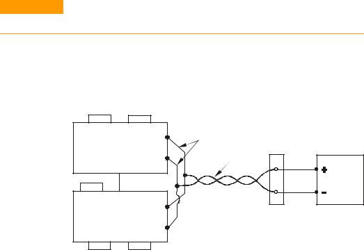
Parallel Connections
CAUTION |
Only power supplies that have identical voltage and current ratings can be |
|||
|
connected in parallel. |
|
||
|
Up to four units of the same voltage and current rating can be |
|||
|
connected in parallel to provide up to four times the output current |
|||
|
capability. Refer to the following figures for typical connections of |
|||
|
parallel power supplies using either local or remote sensing. The |
|||
|
figures show two units, however, the same connection method |
|||
|
applies for up to four units. |
|||
|
-S |
-LS +LS |
+S |
As short as possible |
|
MASTER |
+V |
||
|
|
Twisted |
||
|
POWER SUPPLY |
-V |
||
|
pair |
|||
|
|
J1-25 |
|
|
|
|
Parallel |
|
LOAD |
|
|
Current Program |
||
|
|
|
||
|
J1-8 J1-12 J1-10 |
|
|
|
|
SLAVE |
|
+V |
|
|
POWER SUPPLY |
-V |
|
|
|
-S |
-LS +LS |
|
|
|
+S |
|
||
Local Sensing
28 |
Series N5700 User’s Guide |
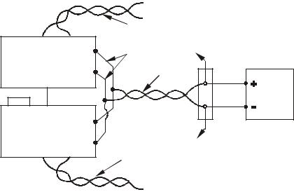
Installation 2
|
|
|
+S |
|
|
|
|
-S |
|
|
|
|
Twisted |
|
-S |
+S |
|
pair |
|
+V |
As short as possible |
|||
MASTER |
|
|||
|
|
+S |
||
POWER SUPPLY -V |
Twisted |
|||
pair |
||||
J1-25 |
|
|
||
|
Parallel |
|
LOAD |
|
|
Current Program |
|||
|
|
|||
J1-8 J1-12 J1-10 |
|
|
||
SLAVE |
|
+V |
|
|
POWER SUPPLY |
-V |
-S |
||
-S |
+S |
Twisted |
||
|
||||
|
|
|
pair |
|
 -S
-S
+S
Remote Sensing
One of the units operates as a master and the remaining units are slaves. The slave units operate as controlled current sources following the master output current. In remote operation, only the master unit can be programmed by the computer while the slave units may be connected to the computer for voltage, current and status readback only.
It is recommended that each unit supplies only up to 95% of its current rating because of the imbalance that may be caused by cabling and connections voltage drops.
Setting up the Master Unit
Connect the sensing circuit for either local or remote sensing as shown in the previous figures. Set the master unit output voltage to the desired voltage. Program the current limit to the desired load current limit divided by the number of parallel units. During operation, the master unit operates in constant voltage mode, regulating the load voltage at the programmed output voltage.
Setting up the Slave Units
Set the rear panel setup switch SW1 position 2 to it’s up position. Connect J1 pin 10 (Current Program) of the slave unit to J1 pin 25 (Parallel) of the master unit. Also connect a short between J1 pin 8 and J1 pin 12. The output voltage of the slave units should be programmed higher than the output voltage of the master unit to prevent interference with the master unit’s control. The current limit of each unit should be programmed to the desired load current limit divided by the number of parallel units.
Series N5700 User’s Guide |
29 |
2 Installation
Setting the Over-Voltage Protection
The master unit OVP should be programmed to the desired OVP level. The OVP of the slave units should be programmed to a higher value than the master. When the master unit shuts down, it programs the slave unit to zero output voltage. If a slave unit shuts down when its OVP is set lower than the master output voltage, only that unit shuts down and the remaining slave units will supply all the load current.
Setting the Over-Current Protection
|
|
Over-current protection, if desired, may only be used with the master |
|
|
unit. When the master unit shuts down, it programs the slave units to |
|
|
zero output voltage. |
Series Connections |
|
|
|
|
SHOCK HAZARD For models up to 60VDC rated output, no point shall be more |
|
WARNING |
|
|
|
than +/-60VDC above/below chassis ground. For models > 60VDC rated |
|
|
output, no point shall be more than +/-600VDC above/below chassis ground. |
|
|
There is also a potential shock hazard at the IEEE/LAN/USB ports when |
|
|
using power supplies with rated or combined voltages > 400VDC with the |
|
|
positive output of the power supplies grounded. Do not connect the positive |
|
|
output to ground when using the IEEE/LAN/USB under the above conditions. |
|
|
|
|
|
Only power supplies that have identical voltage and current ratings can be |
|
CAUTION |
|
|
|
connected in series. |
|
|
|
|
|
Two units of the same voltage and current rating can be connected in |
|
|
series to provide up to two times the output voltage capability. |
|
|
Because the current is the same through each element in a series |
|
|
circuit, outputs connected in series must have equivalent current |
|
|
ratings. Otherwise, the higher rated output could potentially damage |
|
|
the lower rated output by forcing excessive current through it under |
|
|
certain load conditions. Refer to the following figures for typical |
|
|
series connections using either local or remote sensing. |
|
|
It is recommended that diodes be connected in parallel with each |
|
|
output to prevent reverse voltage during start up sequence or in case |
|
|
one unit shuts down. Each diode should be rated to at least the rated |
|
|
output voltage and output current of the power supply. |
30 |
Series N5700 User’s Guide |
Loading...