


 Loading...
User’s Guide
Agilent Technologies
PSG Signal Generators
This guide applies to the following signal generator models:
E8267C PSG Vector Signal Generator
E8257C PSG Analog Signal Generator
E8247C PSG CW Signal Generator
Due to our continuing efforts to improve our products through firmware and hardware revisions, signal generator design and operation may vary from descriptions in this guide. We recommend that you use the latest revision of this guide to ensure you have up-to-date product information. Compare the print date of this guide (see bottom of page) with the latest revision, which can be downloaded from the following website:
www.agilent.com/find/psg
Manufacturing Part Number: E8251-90253
Printed in USA
December 2003
© Copyright 2002, 2003 Agilent Technologies, Inc.

Notice
The material contained in this document is provided “as is”, and is subject to being changed, without notice, in future editions.
Further, to the maximum extent permitted by applicable law, Agilent disclaims all warranties, either express or implied with regard to this manual and to any of the Agilent products to which it pertains, including but not limited to the implied warranties of merchantability and fitness for a particular purpose. Agilent shall not be liable for errors or for incidental or consequential damages in connection with the furnishing, use, or performance of this document or any of the Agilent products to which it pertains. Should Agilent have a written contract with the User and should any of the contract terms conflict with these terms, the contract terms shall control.
Questions or Comments about our Documentation?
We welcome any questions or comments you may have about our documentation. Please send us an E-mail at sources_manuals@am.exch.agilent.com.
ii

Contents
1. Signal Generator Overview . . . . . . . . . . . . . . . . . . . . . . . . . . . . . . . . . . . . . . . . . . . . . . . . . . . . . . . 1
Signal Generator Models and Features . . . . . . . . . . . . . . . . . . . . . . . . . . . . . . . . . . . . . . . . . . . . . . . . .2
E8247C PSG CW Signal Generator Features . . . . . . . . . . . . . . . . . . . . . . . . . . . . . . . . . . . . . . . . . .2
E8257C PSG Analog Signal Generator Features . . . . . . . . . . . . . . . . . . . . . . . . . . . . . . . . . . . . . . .3
E8267C PSG Vector Signal Generator Features . . . . . . . . . . . . . . . . . . . . . . . . . . . . . . . . . . . . . . . .4
Options . . . . . . . . . . . . . . . . . . . . . . . . . . . . . . . . . . . . . . . . . . . . . . . . . . . . . . . . . . . . . . . . . . . . . . . . .4
Firmware Upgrades. . . . . . . . . . . . . . . . . . . . . . . . . . . . . . . . . . . . . . . . . . . . . . . . . . . . . . . . . . . . . . . .4
Modes of Operation . . . . . . . . . . . . . . . . . . . . . . . . . . . . . . . . . . . . . . . . . . . . . . . . . . . . . . . . . . . . . . .5
Front Panel . . . . . . . . . . . . . . . . . . . . . . . . . . . . . . . . . . . . . . . . . . . . . . . . . . . . . . . . . . . . . . . . . . . . . .6
1. Display . . . . . . . . . . . . . . . . . . . . . . . . . . . . . . . . . . . . . . . . . . . . . . . . . . . . . . . . . . . . . . . . . . . . .7
2. Softkeys. . . . . . . . . . . . . . . . . . . . . . . . . . . . . . . . . . . . . . . . . . . . . . . . . . . . . . . . . . . . . . . . . . . . .7
3. Knob . . . . . . . . . . . . . . . . . . . . . . . . . . . . . . . . . . . . . . . . . . . . . . . . . . . . . . . . . . . . . . . . . . . . . . .7
4. Amplitude . . . . . . . . . . . . . . . . . . . . . . . . . . . . . . . . . . . . . . . . . . . . . . . . . . . . . . . . . . . . . . . . . . .7
5. Frequency . . . . . . . . . . . . . . . . . . . . . . . . . . . . . . . . . . . . . . . . . . . . . . . . . . . . . . . . . . . . . . . . . . .7
6. Save . . . . . . . . . . . . . . . . . . . . . . . . . . . . . . . . . . . . . . . . . . . . . . . . . . . . . . . . . . . . . . . . . . . . . . . .7
7. Recall. . . . . . . . . . . . . . . . . . . . . . . . . . . . . . . . . . . . . . . . . . . . . . . . . . . . . . . . . . . . . . . . . . . . . . .7
8. Trigger . . . . . . . . . . . . . . . . . . . . . . . . . . . . . . . . . . . . . . . . . . . . . . . . . . . . . . . . . . . . . . . . . . . . . .8
9. MENUS. . . . . . . . . . . . . . . . . . . . . . . . . . . . . . . . . . . . . . . . . . . . . . . . . . . . . . . . . . . . . . . . . . . . .8
10. Help . . . . . . . . . . . . . . . . . . . . . . . . . . . . . . . . . . . . . . . . . . . . . . . . . . . . . . . . . . . . . . . . . . . . . . .8
11. EXT 1 INPUT . . . . . . . . . . . . . . . . . . . . . . . . . . . . . . . . . . . . . . . . . . . . . . . . . . . . . . . . . . . . . . .8
12. EXT 2 INPUT . . . . . . . . . . . . . . . . . . . . . . . . . . . . . . . . . . . . . . . . . . . . . . . . . . . . . . . . . . . . . . .9
13. LF OUTPUT . . . . . . . . . . . . . . . . . . . . . . . . . . . . . . . . . . . . . . . . . . . . . . . . . . . . . . . . . . . . . . . .9
14. Mod On/Off. . . . . . . . . . . . . . . . . . . . . . . . . . . . . . . . . . . . . . . . . . . . . . . . . . . . . . . . . . . . . . . . .9
15. ALC INPUT . . . . . . . . . . . . . . . . . . . . . . . . . . . . . . . . . . . . . . . . . . . . . . . . . . . . . . . . . . . . . . . .9
16. RF On/Off . . . . . . . . . . . . . . . . . . . . . . . . . . . . . . . . . . . . . . . . . . . . . . . . . . . . . . . . . . . . . . . . . .9
17. Numeric Keypad . . . . . . . . . . . . . . . . . . . . . . . . . . . . . . . . . . . . . . . . . . . . . . . . . . . . . . . . . . . . .9
18. RF OUTPUT . . . . . . . . . . . . . . . . . . . . . . . . . . . . . . . . . . . . . . . . . . . . . . . . . . . . . . . . . . . . . . .10
19. SYNC OUT . . . . . . . . . . . . . . . . . . . . . . . . . . . . . . . . . . . . . . . . . . . . . . . . . . . . . . . . . . . . . . . .10
20. VIDEO OUT . . . . . . . . . . . . . . . . . . . . . . . . . . . . . . . . . . . . . . . . . . . . . . . . . . . . . . . . . . . . . . .10
21. Line Power LED . . . . . . . . . . . . . . . . . . . . . . . . . . . . . . . . . . . . . . . . . . . . . . . . . . . . . . . . . . . .10
22. Power Switch. . . . . . . . . . . . . . . . . . . . . . . . . . . . . . . . . . . . . . . . . . . . . . . . . . . . . . . . . . . . . . .10
23. Standby LED . . . . . . . . . . . . . . . . . . . . . . . . . . . . . . . . . . . . . . . . . . . . . . . . . . . . . . . . . . . . . . .10
24. Incr Set . . . . . . . . . . . . . . . . . . . . . . . . . . . . . . . . . . . . . . . . . . . . . . . . . . . . . . . . . . . . . . . . . . .10
25. GATE/PULSE/TRIGGER INPUT . . . . . . . . . . . . . . . . . . . . . . . . . . . . . . . . . . . . . . . . . . . . . .10
26. Arrows. . . . . . . . . . . . . . . . . . . . . . . . . . . . . . . . . . . . . . . . . . . . . . . . . . . . . . . . . . . . . . . . . . . . 11
27. Hold . . . . . . . . . . . . . . . . . . . . . . . . . . . . . . . . . . . . . . . . . . . . . . . . . . . . . . . . . . . . . . . . . . . . . . 11
28. Return . . . . . . . . . . . . . . . . . . . . . . . . . . . . . . . . . . . . . . . . . . . . . . . . . . . . . . . . . . . . . . . . . . . . 11
29. Display Contrast Decrease . . . . . . . . . . . . . . . . . . . . . . . . . . . . . . . . . . . . . . . . . . . . . . . . . . . . 11
iii

Contents
30. Display Contrast Increase . . . . . . . . . . . . . . . . . . . . . . . . . . . . . . . . . . . . . . . . . . . . . . . . . . . . . 11 31. Local . . . . . . . . . . . . . . . . . . . . . . . . . . . . . . . . . . . . . . . . . . . . . . . . . . . . . . . . . . . . . . . . . . . . . 11 32. Preset. . . . . . . . . . . . . . . . . . . . . . . . . . . . . . . . . . . . . . . . . . . . . . . . . . . . . . . . . . . . . . . . . . . . . 11 33. I/Q INPUTS . . . . . . . . . . . . . . . . . . . . . . . . . . . . . . . . . . . . . . . . . . . . . . . . . . . . . . . . . . . . . . . 12 34. DATA INPUT . . . . . . . . . . . . . . . . . . . . . . . . . . . . . . . . . . . . . . . . . . . . . . . . . . . . . . . . . . . . . . 12 35. DATA CLOCK INPUT. . . . . . . . . . . . . . . . . . . . . . . . . . . . . . . . . . . . . . . . . . . . . . . . . . . . . . . 12 36. SYMBOL SYNC INPUT . . . . . . . . . . . . . . . . . . . . . . . . . . . . . . . . . . . . . . . . . . . . . . . . . . . . . 12
Front Panel Display . . . . . . . . . . . . . . . . . . . . . . . . . . . . . . . . . . . . . . . . . . . . . . . . . . . . . . . . . . . . . . 13
1. Active Entry Area . . . . . . . . . . . . . . . . . . . . . . . . . . . . . . . . . . . . . . . . . . . . . . . . . . . . . . . . . . . . 13
2. Frequency Area. . . . . . . . . . . . . . . . . . . . . . . . . . . . . . . . . . . . . . . . . . . . . . . . . . . . . . . . . . . . . . 13
3. Annunciators . . . . . . . . . . . . . . . . . . . . . . . . . . . . . . . . . . . . . . . . . . . . . . . . . . . . . . . . . . . . . . . . 14
4. Digital Modulation Annunciators . . . . . . . . . . . . . . . . . . . . . . . . . . . . . . . . . . . . . . . . . . . . . . . . 16
5. Amplitude Area. . . . . . . . . . . . . . . . . . . . . . . . . . . . . . . . . . . . . . . . . . . . . . . . . . . . . . . . . . . . . . 16
6. Error Message Area . . . . . . . . . . . . . . . . . . . . . . . . . . . . . . . . . . . . . . . . . . . . . . . . . . . . . . . . . . 16
7. Text Area. . . . . . . . . . . . . . . . . . . . . . . . . . . . . . . . . . . . . . . . . . . . . . . . . . . . . . . . . . . . . . . . . . . 16
8. Softkey Label Area . . . . . . . . . . . . . . . . . . . . . . . . . . . . . . . . . . . . . . . . . . . . . . . . . . . . . . . . . . . 16
Rear Panel. . . . . . . . . . . . . . . . . . . . . . . . . . . . . . . . . . . . . . . . . . . . . . . . . . . . . . . . . . . . . . . . . . . . . . 17 1. AC Power Receptacle . . . . . . . . . . . . . . . . . . . . . . . . . . . . . . . . . . . . . . . . . . . . . . . . . . . . . . . . . 18 2. GPIB . . . . . . . . . . . . . . . . . . . . . . . . . . . . . . . . . . . . . . . . . . . . . . . . . . . . . . . . . . . . . . . . . . . . . . 18 3. AUXILIARY INTERFACE . . . . . . . . . . . . . . . . . . . . . . . . . . . . . . . . . . . . . . . . . . . . . . . . . . . . 18 4. LAN . . . . . . . . . . . . . . . . . . . . . . . . . . . . . . . . . . . . . . . . . . . . . . . . . . . . . . . . . . . . . . . . . . . . . . 18 5. STOP SWEEP IN/OUT . . . . . . . . . . . . . . . . . . . . . . . . . . . . . . . . . . . . . . . . . . . . . . . . . . . . . . . 19 6. Z-AXIS BLANK/MKRS . . . . . . . . . . . . . . . . . . . . . . . . . . . . . . . . . . . . . . . . . . . . . . . . . . . . . . 19 7. SWEEP OUT . . . . . . . . . . . . . . . . . . . . . . . . . . . . . . . . . . . . . . . . . . . . . . . . . . . . . . . . . . . . . . . 19 8. TRIGGER OUT . . . . . . . . . . . . . . . . . . . . . . . . . . . . . . . . . . . . . . . . . . . . . . . . . . . . . . . . . . . . . 19 9. TRIGGER IN . . . . . . . . . . . . . . . . . . . . . . . . . . . . . . . . . . . . . . . . . . . . . . . . . . . . . . . . . . . . . . . 19 10. SOURCE SETTLED . . . . . . . . . . . . . . . . . . . . . . . . . . . . . . . . . . . . . . . . . . . . . . . . . . . . . . . . 19 11. EVENT 1. . . . . . . . . . . . . . . . . . . . . . . . . . . . . . . . . . . . . . . . . . . . . . . . . . . . . . . . . . . . . . . . . . 20 12. EVENT 2 . . . . . . . . . . . . . . . . . . . . . . . . . . . . . . . . . . . . . . . . . . . . . . . . . . . . . . . . . . . . . . . . . 20 13. PATTERN TRIG IN . . . . . . . . . . . . . . . . . . . . . . . . . . . . . . . . . . . . . . . . . . . . . . . . . . . . . . . . . 20 14. BURST GATE IN . . . . . . . . . . . . . . . . . . . . . . . . . . . . . . . . . . . . . . . . . . . . . . . . . . . . . . . . . . . 20 15. AUXILIARY I/O . . . . . . . . . . . . . . . . . . . . . . . . . . . . . . . . . . . . . . . . . . . . . . . . . . . . . . . . . . . 21 16. Digital Bus . . . . . . . . . . . . . . . . . . . . . . . . . . . . . . . . . . . . . . . . . . . . . . . . . . . . . . . . . . . . . . . . 22 17. WIDEBAND I INPUT . . . . . . . . . . . . . . . . . . . . . . . . . . . . . . . . . . . . . . . . . . . . . . . . . . . . . . . 22 18. WIDEBAND Q INPUT . . . . . . . . . . . . . . . . . . . . . . . . . . . . . . . . . . . . . . . . . . . . . . . . . . . . . . 22 19. COH (COHERENT CARRIER OUTPUT) . . . . . . . . . . . . . . . . . . . . . . . . . . . . . . . . . . . . . . . 22 20. I OUT . . . . . . . . . . . . . . . . . . . . . . . . . . . . . . . . . . . . . . . . . . . . . . . . . . . . . . . . . . . . . . . . . . . . 22 21. I-bar OUT . . . . . . . . . . . . . . . . . . . . . . . . . . . . . . . . . . . . . . . . . . . . . . . . . . . . . . . . . . . . . . . . . 23
iv

Contents
22. Q OUT. . . . . . . . . . . . . . . . . . . . . . . . . . . . . . . . . . . . . . . . . . . . . . . . . . . . . . . . . . . . . . . . . . . .23
23. Q-bar OUT . . . . . . . . . . . . . . . . . . . . . . . . . . . . . . . . . . . . . . . . . . . . . . . . . . . . . . . . . . . . . . . .23
24. BASEBAND GEN REF IN. . . . . . . . . . . . . . . . . . . . . . . . . . . . . . . . . . . . . . . . . . . . . . . . . . . .23
25. SMI (SOURCE MODULE INTERFACE) . . . . . . . . . . . . . . . . . . . . . . . . . . . . . . . . . . . . . . . .24
26. 10 MHz OUT . . . . . . . . . . . . . . . . . . . . . . . . . . . . . . . . . . . . . . . . . . . . . . . . . . . . . . . . . . . . . .24
27. 10 MHz IN . . . . . . . . . . . . . . . . . . . . . . . . . . . . . . . . . . . . . . . . . . . . . . . . . . . . . . . . . . . . . . . .24
28. 10 MHz EFC (Option UNR) . . . . . . . . . . . . . . . . . . . . . . . . . . . . . . . . . . . . . . . . . . . . . . . . . . .24
2. Basic Operation. . . . . . . . . . . . . . . . . . . . . . . . . . . . . . . . . . . . . . . . . . . . . . . . . . . . . . . . . . . . . . . . .25
Using Table Editors. . . . . . . . . . . . . . . . . . . . . . . . . . . . . . . . . . . . . . . . . . . . . . . . . . . . . . . . . . . . . . .26 Table Editor Softkeys . . . . . . . . . . . . . . . . . . . . . . . . . . . . . . . . . . . . . . . . . . . . . . . . . . . . . . . . . . .27 Modifying Table Items in the Data Fields. . . . . . . . . . . . . . . . . . . . . . . . . . . . . . . . . . . . . . . . . . . .27 Configuring the RF Output . . . . . . . . . . . . . . . . . . . . . . . . . . . . . . . . . . . . . . . . . . . . . . . . . . . . . . . . .28 Configuring a Continuous Wave RF Output . . . . . . . . . . . . . . . . . . . . . . . . . . . . . . . . . . . . . . . . . .28 Configuring a Swept RF Output . . . . . . . . . . . . . . . . . . . . . . . . . . . . . . . . . . . . . . . . . . . . . . . . . . .31 Extending the Frequency Range with a mm-Wave Source Module . . . . . . . . . . . . . . . . . . . . . . . .47 Modulating a Signal . . . . . . . . . . . . . . . . . . . . . . . . . . . . . . . . . . . . . . . . . . . . . . . . . . . . . . . . . . . . . .50 Turning On a Modulation Format . . . . . . . . . . . . . . . . . . . . . . . . . . . . . . . . . . . . . . . . . . . . . . . . . .50 Applying a Modulation Format to the RF Output. . . . . . . . . . . . . . . . . . . . . . . . . . . . . . . . . . . . . .51 Using Data Storage Functions . . . . . . . . . . . . . . . . . . . . . . . . . . . . . . . . . . . . . . . . . . . . . . . . . . . . . .52 Using the Memory Catalog . . . . . . . . . . . . . . . . . . . . . . . . . . . . . . . . . . . . . . . . . . . . . . . . . . . . . . .52 Using the Instrument State Register . . . . . . . . . . . . . . . . . . . . . . . . . . . . . . . . . . . . . . . . . . . . . . . .54 Enabling Options . . . . . . . . . . . . . . . . . . . . . . . . . . . . . . . . . . . . . . . . . . . . . . . . . . . . . . . . . . . . . . . .57 Enabling a Software Option . . . . . . . . . . . . . . . . . . . . . . . . . . . . . . . . . . . . . . . . . . . . . . . . . . . . . .57
3. Optimizing Performance . . . . . . . . . . . . . . . . . . . . . . . . . . . . . . . . . . . . . . . . . . . . . . . . . . . . . . . . . .59
Selecting ALC Bandwidth . . . . . . . . . . . . . . . . . . . . . . . . . . . . . . . . . . . . . . . . . . . . . . . . . . . . . . . . .59 To Select an ALC Bandwidth . . . . . . . . . . . . . . . . . . . . . . . . . . . . . . . . . . . . . . . . . . . . . . . . . . . . .59 Using External Leveling . . . . . . . . . . . . . . . . . . . . . . . . . . . . . . . . . . . . . . . . . . . . . . . . . . . . . . . . . . .60 To Level with Detectors and Couplers/Splitters . . . . . . . . . . . . . . . . . . . . . . . . . . . . . . . . . . . . . . .60 To Level with a mm-Wave Source Module. . . . . . . . . . . . . . . . . . . . . . . . . . . . . . . . . . . . . . . . . . .63 Creating and Applying User Flatness Correction . . . . . . . . . . . . . . . . . . . . . . . . . . . . . . . . . . . . . . . .64 Creating a User Flatness Correction Array . . . . . . . . . . . . . . . . . . . . . . . . . . . . . . . . . . . . . . . . . . .64 Creating a User Flatness Correction Array with a mm-Wave Source Module . . . . . . . . . . . . . . . .69 Adjusting Reference Oscillator Bandwidth (Option UNR) . . . . . . . . . . . . . . . . . . . . . . . . . . . . . . . .76 To Select the Reference Oscillator Bandwidth. . . . . . . . . . . . . . . . . . . . . . . . . . . . . . . . . . . . . . . .76 To Restore Factory Default Settings: . . . . . . . . . . . . . . . . . . . . . . . . . . . . . . . . . . . . . . . . . . . . . . .76
v

Contents
4. Analog Modulation. . . . . . . . . . . . . . . . . . . . . . . . . . . . . . . . . . . . . . . . . . . . . . . . . . . . . . . . . . . . . . 77
Analog Modulation Waveforms . . . . . . . . . . . . . . . . . . . . . . . . . . . . . . . . . . . . . . . . . . . . . . . . . . . . . 78 Configuring AM . . . . . . . . . . . . . . . . . . . . . . . . . . . . . . . . . . . . . . . . . . . . . . . . . . . . . . . . . . . . . . . . . 79 To Set the Carrier Frequency . . . . . . . . . . . . . . . . . . . . . . . . . . . . . . . . . . . . . . . . . . . . . . . . . . . . . 79 To Set the RF Output Amplitude . . . . . . . . . . . . . . . . . . . . . . . . . . . . . . . . . . . . . . . . . . . . . . . . . . 79 To Set the AM Depth and Rate . . . . . . . . . . . . . . . . . . . . . . . . . . . . . . . . . . . . . . . . . . . . . . . . . . . . 79 To Turn on Amplitude Modulation . . . . . . . . . . . . . . . . . . . . . . . . . . . . . . . . . . . . . . . . . . . . . . . . . 79 Configuring FM . . . . . . . . . . . . . . . . . . . . . . . . . . . . . . . . . . . . . . . . . . . . . . . . . . . . . . . . . . . . . . . . . 80 To Set the RF Output Frequency . . . . . . . . . . . . . . . . . . . . . . . . . . . . . . . . . . . . . . . . . . . . . . . . . . 80 To Set the RF Output Amplitude . . . . . . . . . . . . . . . . . . . . . . . . . . . . . . . . . . . . . . . . . . . . . . . . . . 80 To Set the FM Deviation and Rate . . . . . . . . . . . . . . . . . . . . . . . . . . . . . . . . . . . . . . . . . . . . . . . . . 80 To Activate FM . . . . . . . . . . . . . . . . . . . . . . . . . . . . . . . . . . . . . . . . . . . . . . . . . . . . . . . . . . . . . . . . 80 Configuring Φ M . . . . . . . . . . . . . . . . . . . . . . . . . . . . . . . . . . . . . . . . . . . . . . . . . . . . . . . . . . . . . . . . . 81 To Set the RF Output Frequency . . . . . . . . . . . . . . . . . . . . . . . . . . . . . . . . . . . . . . . . . . . . . . . . . . 81 To Set the RF Output Amplitude . . . . . . . . . . . . . . . . . . . . . . . . . . . . . . . . . . . . . . . . . . . . . . . . . . 81 To Set the FM Deviation and Rate . . . . . . . . . . . . . . . . . . . . . . . . . . . . . . . . . . . . . . . . . . . . . . . . . 81 To Activate FM . . . . . . . . . . . . . . . . . . . . . . . . . . . . . . . . . . . . . . . . . . . . . . . . . . . . . . . . . . . . . . . . 81 Configuring Pulse Modulation . . . . . . . . . . . . . . . . . . . . . . . . . . . . . . . . . . . . . . . . . . . . . . . . . . . . . . 82 To Set the RF Output Frequency . . . . . . . . . . . . . . . . . . . . . . . . . . . . . . . . . . . . . . . . . . . . . . . . . . 82 To Set the RF Output Amplitude . . . . . . . . . . . . . . . . . . . . . . . . . . . . . . . . . . . . . . . . . . . . . . . . . . 82 To Set the Pulse Period and Width . . . . . . . . . . . . . . . . . . . . . . . . . . . . . . . . . . . . . . . . . . . . . . . . . 82 To Activate Pulse Modulation . . . . . . . . . . . . . . . . . . . . . . . . . . . . . . . . . . . . . . . . . . . . . . . . . . . . 82 Configuring the LF Output . . . . . . . . . . . . . . . . . . . . . . . . . . . . . . . . . . . . . . . . . . . . . . . . . . . . . . . . 83 To Configure the LF Output with an Internal Modulation Source . . . . . . . . . . . . . . . . . . . . . . . . . 84 To Configure the LF Output with a Function Generator Source . . . . . . . . . . . . . . . . . . . . . . . . . . 85
5. Dual Arbitrary Waveform Generator. . . . . . . . . . . . . . . . . . . . . . . . . . . . . . . . . . . . . . . . . . . . . . . . 87
Arbitrary (ARB) Waveform File Headers . . . . . . . . . . . . . . . . . . . . . . . . . . . . . . . . . . . . . . . . . . . . . 88 Creating a File Header for a Modulation Format Waveform . . . . . . . . . . . . . . . . . . . . . . . . . . . . . 89 Modifying Header Information in a Modulation Format . . . . . . . . . . . . . . . . . . . . . . . . . . . . . . . . 90 Storing Header Information for a Dual ARB Player Waveform Sequence . . . . . . . . . . . . . . . . . . 95 Modifying and Viewing Header Information in the Dual ARB Player . . . . . . . . . . . . . . . . . . . . . 95 Playing a Waveform File that Contains a Header . . . . . . . . . . . . . . . . . . . . . . . . . . . . . . . . . . . . . . 98
Using the Dual ARB Waveform Player . . . . . . . . . . . . . . . . . . . . . . . . . . . . . . . . . . . . . . . . . . . . . . . 99
Accessing the Dual ARB Player . . . . . . . . . . . . . . . . . . . . . . . . . . . . . . . . . . . . . . . . . . . . . . . . . . . 99
Creating Waveform Segments . . . . . . . . . . . . . . . . . . . . . . . . . . . . . . . . . . . . . . . . . . . . . . . . . . . 100
Building and Storing a Waveform Sequence . . . . . . . . . . . . . . . . . . . . . . . . . . . . . . . . . . . . . . . . 101
Playing a Waveform . . . . . . . . . . . . . . . . . . . . . . . . . . . . . . . . . . . . . . . . . . . . . . . . . . . . . . . . . . . 102
vi

Contents
Editing a Waveform Sequence . . . . . . . . . . . . . . . . . . . . . . . . . . . . . . . . . . . . . . . . . . . . . . . . . . .102 Storing and Loading Waveform Segments . . . . . . . . . . . . . . . . . . . . . . . . . . . . . . . . . . . . . . . . . .103 Renaming a Waveform Segment. . . . . . . . . . . . . . . . . . . . . . . . . . . . . . . . . . . . . . . . . . . . . . . . . .103 Using Waveform Markers. . . . . . . . . . . . . . . . . . . . . . . . . . . . . . . . . . . . . . . . . . . . . . . . . . . . . . . . .104 To Place a Marker at the First Point within a Waveform Segment . . . . . . . . . . . . . . . . . . . . . . . .104 To Place a Marker Across a Range of Points within a Waveform Segment . . . . . . . . . . . . . . . . .104 To Place Repetitively Spaced Markers within a Waveform Segment. . . . . . . . . . . . . . . . . . . . . .105 To Use Marker 2 to Blank the RF Output . . . . . . . . . . . . . . . . . . . . . . . . . . . . . . . . . . . . . . . . . . .105 To Toggle Markers in an Existing Waveform Sequence . . . . . . . . . . . . . . . . . . . . . . . . . . . . . . . .106 To Toggle Markers As You Create a Waveform Sequence . . . . . . . . . . . . . . . . . . . . . . . . . . . . . .107 To Verify Marker Operation . . . . . . . . . . . . . . . . . . . . . . . . . . . . . . . . . . . . . . . . . . . . . . . . . . . . .107 Waveform Marker Concepts . . . . . . . . . . . . . . . . . . . . . . . . . . . . . . . . . . . . . . . . . . . . . . . . . . . . .108 Using Waveform Triggers. . . . . . . . . . . . . . . . . . . . . . . . . . . . . . . . . . . . . . . . . . . . . . . . . . . . . . . . . 111 To Use Segment Advance Triggering . . . . . . . . . . . . . . . . . . . . . . . . . . . . . . . . . . . . . . . . . . . . . . 111 Using Waveform Clipping . . . . . . . . . . . . . . . . . . . . . . . . . . . . . . . . . . . . . . . . . . . . . . . . . . . . . . . . 112 To Configure Circular Clipping . . . . . . . . . . . . . . . . . . . . . . . . . . . . . . . . . . . . . . . . . . . . . . . . . . 112 To Configure Rectangular Clipping . . . . . . . . . . . . . . . . . . . . . . . . . . . . . . . . . . . . . . . . . . . . . . . 112 Waveform Clipping Concepts . . . . . . . . . . . . . . . . . . . . . . . . . . . . . . . . . . . . . . . . . . . . . . . . . . . . 113
6. Custom Arb Waveform Generator . . . . . . . . . . . . . . . . . . . . . . . . . . . . . . . . . . . . . . . . . . . . . . . . .119
Overview. . . . . . . . . . . . . . . . . . . . . . . . . . . . . . . . . . . . . . . . . . . . . . . . . . . . . . . . . . . . . . . . . . . . . .120 Working with Predefined Setups (Modes) . . . . . . . . . . . . . . . . . . . . . . . . . . . . . . . . . . . . . . . . . . . .121 Selecting a Custom ARB Setup or a Custom Digital Modulation State . . . . . . . . . . . . . . . . . . . .121 Working with User-Defined Setups (Modes)-Custom Arb Only . . . . . . . . . . . . . . . . . . . . . . . . . . .122 Modifying a Single-Carrier NADC Setup. . . . . . . . . . . . . . . . . . . . . . . . . . . . . . . . . . . . . . . . . . .122 Customizing a Multicarrier Setup . . . . . . . . . . . . . . . . . . . . . . . . . . . . . . . . . . . . . . . . . . . . . . . . .123 Recalling a User-Defined Custom Digital Modulation State . . . . . . . . . . . . . . . . . . . . . . . . . . . .124 Working with Filters . . . . . . . . . . . . . . . . . . . . . . . . . . . . . . . . . . . . . . . . . . . . . . . . . . . . . . . . . . . . .125 Using a Predefined FIR Filter . . . . . . . . . . . . . . . . . . . . . . . . . . . . . . . . . . . . . . . . . . . . . . . . . . . .126 Using a User-Defined FIR Filter . . . . . . . . . . . . . . . . . . . . . . . . . . . . . . . . . . . . . . . . . . . . . . . . . .127 Working with Symbol Rates . . . . . . . . . . . . . . . . . . . . . . . . . . . . . . . . . . . . . . . . . . . . . . . . . . . . . . .133 To Set a Symbol Rate . . . . . . . . . . . . . . . . . . . . . . . . . . . . . . . . . . . . . . . . . . . . . . . . . . . . . . . . . .133 To Restore the Default Symbol Rate (Custom Real Time I/Q Only) . . . . . . . . . . . . . . . . . . . . . .133 Working with Modulation Types . . . . . . . . . . . . . . . . . . . . . . . . . . . . . . . . . . . . . . . . . . . . . . . . . . .136 To Select a Predefined Modulation Type . . . . . . . . . . . . . . . . . . . . . . . . . . . . . . . . . . . . . . . . . . .136 To Use a User-Defined Modulation Type (Real Time I/Q Only) . . . . . . . . . . . . . . . . . . . . . . . . .137 Configuring Hardware . . . . . . . . . . . . . . . . . . . . . . . . . . . . . . . . . . . . . . . . . . . . . . . . . . . . . . . . . . .143 To Set a Delayed, Positive Polarity, External Single Trigger . . . . . . . . . . . . . . . . . . . . . . . . . . . .143
vii

Contents
To Set the ARB Reference . . . . . . . . . . . . . . . . . . . . . . . . . . . . . . . . . . . . . . . . . . . . . . . . . . . . . . 144
7. Custom Real Time I/Q Baseband . . . . . . . . . . . . . . . . . . . . . . . . . . . . . . . . . . . . . . . . . . . . . . . . . 145
Overview . . . . . . . . . . . . . . . . . . . . . . . . . . . . . . . . . . . . . . . . . . . . . . . . . . . . . . . . . . . . . . . . . . . . . 146 Working with Predefined Setups (Modes) . . . . . . . . . . . . . . . . . . . . . . . . . . . . . . . . . . . . . . . . . . . . 146 Selecting a Predefined Real Time Modulation Setup . . . . . . . . . . . . . . . . . . . . . . . . . . . . . . . . . . 146 Deselecting a Predefined Real Time Modulation Setup . . . . . . . . . . . . . . . . . . . . . . . . . . . . . . . . 146 Working with Data Patterns . . . . . . . . . . . . . . . . . . . . . . . . . . . . . . . . . . . . . . . . . . . . . . . . . . . . . . . 147 Using a Predefined Data Pattern . . . . . . . . . . . . . . . . . . . . . . . . . . . . . . . . . . . . . . . . . . . . . . . . . . 148 Using a User-Defined Data Pattern. . . . . . . . . . . . . . . . . . . . . . . . . . . . . . . . . . . . . . . . . . . . . . . . 149 Using an Externally Supplied Data Pattern . . . . . . . . . . . . . . . . . . . . . . . . . . . . . . . . . . . . . . . . . 152 Working with Burst Shapes . . . . . . . . . . . . . . . . . . . . . . . . . . . . . . . . . . . . . . . . . . . . . . . . . . . . . . . 153 Configuring the Burst Rise and Fall Parameters . . . . . . . . . . . . . . . . . . . . . . . . . . . . . . . . . . . . . 154 Using User-Defined Burst Shape Curves . . . . . . . . . . . . . . . . . . . . . . . . . . . . . . . . . . . . . . . . . . . 155 Configuring Hardware . . . . . . . . . . . . . . . . . . . . . . . . . . . . . . . . . . . . . . . . . . . . . . . . . . . . . . . . . . . 158 To Set the BBG Reference . . . . . . . . . . . . . . . . . . . . . . . . . . . . . . . . . . . . . . . . . . . . . . . . . . . . . . 158 To Set the External DATA CLOCK to Receive Input as Either Normal or Symbol . . . . . . . . . . 159 To Set the BBG DATA CLOCK to External or Internal. . . . . . . . . . . . . . . . . . . . . . . . . . . . . . . . 159 To Adjust the I/Q Scaling . . . . . . . . . . . . . . . . . . . . . . . . . . . . . . . . . . . . . . . . . . . . . . . . . . . . . . . 159 Working with Phase Polarity . . . . . . . . . . . . . . . . . . . . . . . . . . . . . . . . . . . . . . . . . . . . . . . . . . . . . . 160 To Set Phase Polarity to Normal or Inverted . . . . . . . . . . . . . . . . . . . . . . . . . . . . . . . . . . . . . . . . 160 Working with Differential Data Encoding . . . . . . . . . . . . . . . . . . . . . . . . . . . . . . . . . . . . . . . . . . . . 160 Understanding Differential Encoding . . . . . . . . . . . . . . . . . . . . . . . . . . . . . . . . . . . . . . . . . . . . . . 160 Using Differential Encoding . . . . . . . . . . . . . . . . . . . . . . . . . . . . . . . . . . . . . . . . . . . . . . . . . . . . . 165
8. Multitone Waveform Generator . . . . . . . . . . . . . . . . . . . . . . . . . . . . . . . . . . . . . . . . . . . . . . . . . . 169
Overview . . . . . . . . . . . . . . . . . . . . . . . . . . . . . . . . . . . . . . . . . . . . . . . . . . . . . . . . . . . . . . . . . . . . . 170 Creating, Viewing, and Optimizing Multitone Waveforms . . . . . . . . . . . . . . . . . . . . . . . . . . . . . . . 171 To Create a Custom Multitone Waveform . . . . . . . . . . . . . . . . . . . . . . . . . . . . . . . . . . . . . . . . . . 171 To View a Multitone Waveform . . . . . . . . . . . . . . . . . . . . . . . . . . . . . . . . . . . . . . . . . . . . . . . . . . 172 To Edit the Multitone Setup Table . . . . . . . . . . . . . . . . . . . . . . . . . . . . . . . . . . . . . . . . . . . . . . . . 173 To Minimize Carrier Feedthrough . . . . . . . . . . . . . . . . . . . . . . . . . . . . . . . . . . . . . . . . . . . . . . . . 175 To Determine Peak to Average Characteristics. . . . . . . . . . . . . . . . . . . . . . . . . . . . . . . . . . . . . . . 177
9. Two-Tone Waveform Generator . . . . . . . . . . . . . . . . . . . . . . . . . . . . . . . . . . . . . . . . . . . . . . . . . . . 179
Overview . . . . . . . . . . . . . . . . . . . . . . . . . . . . . . . . . . . . . . . . . . . . . . . . . . . . . . . . . . . . . . . . . . . . . 180
Creating, Viewing, and Modifying Two-Tone Waveforms . . . . . . . . . . . . . . . . . . . . . . . . . . . . . . . 181
To Create a Two-Tone Waveform . . . . . . . . . . . . . . . . . . . . . . . . . . . . . . . . . . . . . . . . . . . . . . . . . 181
viii

Contents
To View a Two-Tone Waveform . . . . . . . . . . . . . . . . . . . . . . . . . . . . . . . . . . . . . . . . . . . . . . . . . .182 To Minimize Carrier Feedthrough. . . . . . . . . . . . . . . . . . . . . . . . . . . . . . . . . . . . . . . . . . . . . . . . .184 To Change the Alignment of a Two-Tone Waveform . . . . . . . . . . . . . . . . . . . . . . . . . . . . . . . . . .186
10. Troubleshooting . . . . . . . . . . . . . . . . . . . . . . . . . . . . . . . . . . . . . . . . . . . . . . . . . . . . . . . . . . . . . . .187
RF Output Power Problems . . . . . . . . . . . . . . . . . . . . . . . . . . . . . . . . . . . . . . . . . . . . . . . . . . . . . . .189 RF Output Power too Low . . . . . . . . . . . . . . . . . . . . . . . . . . . . . . . . . . . . . . . . . . . . . . . . . . . . . .189 The Power Supply has Shut Down . . . . . . . . . . . . . . . . . . . . . . . . . . . . . . . . . . . . . . . . . . . . . . . .189 Signal Loss While Working with a Mixer. . . . . . . . . . . . . . . . . . . . . . . . . . . . . . . . . . . . . . . . . . .190 Signal Loss While Working with a Spectrum Analyzer . . . . . . . . . . . . . . . . . . . . . . . . . . . . . . . .192
No Modulation at the RF Output . . . . . . . . . . . . . . . . . . . . . . . . . . . . . . . . . . . . . . . . . . . . . . . . . . .193 Sweep Problems . . . . . . . . . . . . . . . . . . . . . . . . . . . . . . . . . . . . . . . . . . . . . . . . . . . . . . . . . . . . . . . .194 Sweep Appears to be Stalled . . . . . . . . . . . . . . . . . . . . . . . . . . . . . . . . . . . . . . . . . . . . . . . . . . . . .194 Cannot Turn Off Sweep Mode . . . . . . . . . . . . . . . . . . . . . . . . . . . . . . . . . . . . . . . . . . . . . . . . . . .194 Incorrect List Sweep Dwell Time . . . . . . . . . . . . . . . . . . . . . . . . . . . . . . . . . . . . . . . . . . . . . . . . .195 List Sweep Information is Missing from a Recalled Register . . . . . . . . . . . . . . . . . . . . . . . . . . .195 Data Storage Problems . . . . . . . . . . . . . . . . . . . . . . . . . . . . . . . . . . . . . . . . . . . . . . . . . . . . . . . . . . .196 Registers With Previously Stored Instrument States are Empty . . . . . . . . . . . . . . . . . . . . . . . . . .196 Saved Instrument State, but Register is Empty or Contains Wrong State. . . . . . . . . . . . . . . . . . .196 Cannot Turn Off Help Mode. . . . . . . . . . . . . . . . . . . . . . . . . . . . . . . . . . . . . . . . . . . . . . . . . . . . . . .197 Signal Generator Locks Up. . . . . . . . . . . . . . . . . . . . . . . . . . . . . . . . . . . . . . . . . . . . . . . . . . . . . . . .198 Fail-Safe Recovery Sequence . . . . . . . . . . . . . . . . . . . . . . . . . . . . . . . . . . . . . . . . . . . . . . . . . . . .198 Error Messages . . . . . . . . . . . . . . . . . . . . . . . . . . . . . . . . . . . . . . . . . . . . . . . . . . . . . . . . . . . . . . . . .200 Error Message File . . . . . . . . . . . . . . . . . . . . . . . . . . . . . . . . . . . . . . . . . . . . . . . . . . . . . . . . . . . .200 Error Message Format. . . . . . . . . . . . . . . . . . . . . . . . . . . . . . . . . . . . . . . . . . . . . . . . . . . . . . . . . .201 Error Message Types . . . . . . . . . . . . . . . . . . . . . . . . . . . . . . . . . . . . . . . . . . . . . . . . . . . . . . . . . . .202 Returning a Signal Generator to Agilent Technologies . . . . . . . . . . . . . . . . . . . . . . . . . . . . . . . . . .203
ix

Contents
x
1 Signal Generator Overview
In the following sections, this chapter describes the models, options, and features available for Agilent PSG signal generators. The modes of operation, front panel user interface, as well as front and rear panel connectors are also described.
•“Signal Generator Models and Features” on page 2
•“Options” on page 4
•“Firmware Upgrades” on page 4
•“Modes of Operation” on page 5
•“Front Panel” on page 6
•“Front Panel Display” on page 13
•“Rear Panel” on page 17
1

Signal Generator Overview
Signal Generator Models and Features
Signal Generator Models and Features
Table 1-1 lists the available PSG signal generator models along with their output signal types and frequency range.
Table 1-1 |
PSG Signal Generator Models |
|
|
|
|
|
|
Model |
|
Type |
Frequency Range |
|
|
|
|
E8247C PSG CW signal generator |
CW |
250 kHz to 20 GHz, or |
|
|
|
|
250 kHz to 40 GHz |
|
|
|
|
E8257C PSG analog signal generator |
Analog |
250 kHz to 20 GHz, or |
|
|
|
|
250 kHz to 40 GHz |
|
|
|
|
E8267C PSG vector signal generator |
Vector |
250 kHz to 20 GHz |
|
|
|
|
|
E8247C PSG CW Signal Generator Features
An E8247C PSG CW signal generator includes the following features:
•CW output from 250 kHz to 20 GHz or 40 GHz
•frequency resolution to 0.001 Hz
•list and step sweep of frequency and amplitude, with multiple trigger sources
•user flatness correction
•external diode detector leveling
•automatic leveling control (ALC) on and off modes; power calibration in ALC-off mode is available, even without power search
•10 MHz reference oscillator with external output
•RS-232, GPIB, and 10Base-T LAN I/O interfaces
•a millimeter head interface that is compatible with Agilent 83550 Series millimeter heads (for frequency extension up to 110 GHz)
2 |
Chapter 1 |

Signal Generator Overview
Signal Generator Models and Features
E8257C PSG Analog Signal Generator Features
An E8257C PSG analog signal generator provides all the functionality of an E8247C PSG CW signal generator and adds the following features:
•open-loop or closed-loop AM
•dc-synthesized FM to 10 MHz rates; maximum deviation depends on the carrier frequency
•phase modulation (Φ M)
•pulse modulation
•external modulation inputs for AM, FM, Φ M, and pulse
•simultaneous modulation configurations (except: FM with Φ M or Linear AM with Exponential AM)
•an internal pulse generator that includes the following:
—selectable pulse modes: internal square, internal free-run, internal triggered, internal doublet, internal gated, and external pulse; internal triggered, internal doublet, and internal gated require an
external trigger source
—adjustable pulse rate
—adjustable pulse period
—adjustable pulse width
—adjustable pulse delay
—selectable external pulse triggering: positive or negative
•dual function generators that includes the following:
—50Ω low frequency output, 0 to 3Vp, available through LF OUTPUT
—selectable waveforms: sine, dual-sine, swept-sine, triangle, positive ramp, negative ramp, square, uniform noise, Gaussian noise, and dc
—adjustable frequency modulation rates
—selectable triggering in list and step sweep modes: free run (auto), trigger key (single), bus (remote), and external
Chapter 1 |
3 |

Signal Generator Overview
Options
E8267C PSG Vector Signal Generator Features
An E8267C PSG vector signal generator provides all the functionality of an E8257C PSG analog signal generator, and adds the following features:
•internal I/Q modulator
•external analog I/Q inputs
•single-ended and differential analog I/Q outputs
Options
PSG signal generators have hardware, firmware, software, and documentation options. The data sheet shipped with your signal generator provides an overview of available options. For details, refer to the Agilent Technologies website.
1.Open: www.agilent.com/find/psg
2.Select the desired model.
3.Click View complete price list.
Firmware Upgrades
The firmware in your signal generator may be upgraded when new firmware is released. New firmware releases may contain signal generator features and functionality not available in previous firmware releases.
To inquire about the availability of new signal generator firmware, contact Agilent at http://www.agilent.com/find/upgradeassistant, or call the appropriate number listed in Table 10-1 on page 203.
4 |
Chapter 1 |

Signal Generator Overview
Modes of Operation
Modes of Operation
All PSG signal generator models can be used in CW mode:
•CW mode produces a single carrier signal.
—If you have an E8247C PSG CW signal generator, you can produce a CW single carrier signal without modulation.
—If you have an E8257C PSG analog signal generator, you can produce a CW single carrier signal without modulation, or you can add AM, FM, Φ M, or Pulse modulation to produce a single carrier
modulated signal; some of these modulations can be used together.
—If you have an E8267C PSG vector signal generator, you can produce a CW single carrier signal without modulation, or you can add AM, FM, Φ M, Pulse, or I/Q modulation to produce a single
carrier modulated signal; some of these modulations can be used together.
In addition to CW and analog mode, all of the following modes are also available to the E8267C PSG vector signal generator:
•Custom Arb Waveform Generator mode can produce a single modulated carrier or multiple modulated carriers. Each modulated carrier waveform must be calculated and generated before it can be output; this signal generation occurs on the internal baseband generator (Option 002/602). Once a waveform has been created, it can be stored and recalled which enables repeatable playback of test signals. To learn more, refer to “Custom Arb Waveform Generator” on page 119.
•Custom Real Time I/Q Baseband mode produces a single carrier, but it can be modulated with real time data that allows real time control over all of the parameters that affect the signal. The single carrier signal that is produced can be modified by applying various data patterns, filters, symbol rates, modulation types, and burst shapes. To learn more, refer to “Custom Real Time I/Q Baseband” on page 145.
•Two Tone mode produces two separate carrier signals without any kind of modulation; the frequency spacing between the two carrier signals is adjustable as well as the amplitude of both carriers. To learn more, refer to “Two-Tone Waveform Generator” on page 179.
•Multitone mode produces any number of carrier signals without any kind of modulation; like Two Tone mode, the frequency spacing between all carrier signals is adjustable as well as the amplitude of all carriers. To learn more, refer to “Multitone Waveform Generator” on page 169.
•Dual ARB mode is used to control the playback sequence of waveform segments that have been written into the ARB memory located on the internal baseband generator (Option 002/602). These waveforms can be generated using the internal baseband generator, in Custom Arb Waveform Generator mode, or downloaded through a remote interface into the ARB memory. To learn more, refer to “Dual Arbitrary Waveform Generator” on page 87.
Chapter 1 |
5 |

Signal Generator Overview
Front Panel
Front Panel
Figure 1-1 shows the E8267C PSG vector signal generator front panel with a list of items called out that enable you to define, monitor, and manage input and output characteristics.
The description of each item also applies to both the E8257C PSG analog signal generator and the E8247C PSG CW signal generator front panels. Not all items being described are available on every signal generator; the list of items that your particular signal generator has is dependent on its model and options.
Figure 1-1 |
Front Panel Diagram (E8267C PSG Vector Signal Generator) |
3. Knob
4. Amplitude
5. Frequency
1. Display |
2. Softkeys |
|||
|
|
|
|
|
|
|
|
|
|
|
|
|
|
|
E8267C Only
 33. I/Q INPUTS 34. DATA INPUT
 35. DATA CLOCK 36. SYMBOL SYNC
 21. Line Power LED
22.Power Switch
23.Standby LED
6. Save
7. Recall
8. Trigger
9. MENUS
10. Help
11. EXT 1 INPUT
12. EXT 2 INPUT
13. LF OUTPUT
14. Mod On/Off
15. ALC INPUT
16. RF On/Off
17. Numeric Keypad
18. RF OUTPUT
19. SYNC OUT
20. VIDEO OUT
24.Incr Set
25.GATE/PULSE/TRIGGER INPUT
26.Arrows
27.Hold
28.Return
29.Display Contrast Decrease
30.Display Contrast Increase
31.Local
32.Preset
6 |
Chapter 1 |

Signal Generator Overview
Front Panel
1. Display
The LCD screen provides information on the current function. Information can include status indicators, frequency and amplitude settings, and error messages. Softkeys labels are located on the right-hand side of the display. For more detail on the front panel display, see “Front Panel Display” on page 13.
2. Softkeys
Softkeys activate the displayed function to the left of each key.
3. Knob
Use the knob to increase or decrease a numeric value, changes a highlighted digit or character, or step through lists or select items in a row.
4. Amplitude
Pressing this hardkey makes amplitude the active function. You can change the output amplitude or use the menus to configure amplitude attributes such as power search, user flatness, and leveling mode.
5. Frequency
Pressing this hardkey makes frequency the active function. You can change the output frequency or use the menus to configure frequency attributes such as frequency multiplier, offset, and reference.
6. Save
Pressing this hardkey accesses a menu of choices enabling you to save data in the instrument state register. The instrument state register is a section of memory divided into 10 sequences (numbered 0 through 9) each containing 100 registers (numbered 00 through 99). It is used to store and recall:
•frequency and amplitude settings on an E8247C PSG CW signal generator
•frequency, amplitude, and modulation settings on an E8257C PSG analog signal generator or E8267C PSG vector signal generator
The Save hardkey provides a quick alternative to reconfiguring the signal generator through the front panel or SCPI commands when switching between different signal configurations. Once an instrument state has been saved, all of the frequency, amplitude, and modulation settings can be recalled with the Recall hardkey.
7. Recall
Restores an instrument state saved in a memory register. Refer to the Save hardkey for further information.
Chapter 1 |
7 |

Signal Generator Overview
Front Panel
8. Trigger
Initiates an immediate trigger event for a function such as a list, step, or ramp sweep (Option 007 only). Before this hardkey can be used to initiate a trigger event, the trigger mode must be set to Trigger Key. For
example: press the Sweep/List hardkey, then one of the following sequences of softkeys:
•More (1 of 2) > Sweep Trigger > Trigger Key
•More (1 of 2) > Point Trigger > Trigger Key
9. MENUS
These keys open softkey menus for configuring various functions. For descriptions, see the Key Reference.
Table 1-2 |
Hardkeys in Front Panel MENUS Group |
||
|
|
|
|
E8247C PSG CW |
E8257C PSG Analog |
E8267C PSG Vector |
|
|
|
|
|
Sweep/List |
AM |
Mode |
FM/Φ |
Utility |
Sweep/List |
Mux |
M |
|
FM/Φ M |
AM |
Utility |
|
Utility |
Sweep/List |
I/Q |
|
Pulse |
Mode Setup |
Pulse |
|
LF Out |
Aux Fctn |
LF Out |
|
|
|
|
10. Help
Pressing this hardkey accesses a short description of any hardkey or softkey. There are two help modes
available on the signal generator: single and continuous. The single mode is the factory preset condition. Toggle between single and continuous mode by pressing Utility > Instrument Info/Help Mode > Help Mode Single Cont.
•In single mode, help text is provided for the next key you press without activating the key’s function. Any key pressed afterward exits the help mode and its function is activated.
•In continuous mode, help text is provided for each subsequent key press until you press the Help hardkey again or change to single mode. In addition, each key is active, meaning that the key function is executed (except for the Preset key).
11. EXT 1 INPUT
This female BNC input connector (E8257C and E8267C only) accepts a ±1Vp signal for AM, FM, and Φ M. For these modulations, ±1 Vp produces the indicated deviation or depth. When ac-coupled inputs are selected for AM, FM, or Φ M and the peak input voltage differs from 1Vp by more than 3%, the HI/LO display annunciators light. The input impedance is selectable as either 50 or 600Ω; the damage levels are
5 Vrms and 10 Vp. On signal generators with Option 1EM, this connector is relocated to the a rear panel.
8 |
Chapter 1 |

Signal Generator Overview
Front Panel
12. EXT 2 INPUT
This female BNC input connector (E8257C and E8267C only) accepts a ±1Vp signal for AM, FM, and Φ M. With AM, FM, or Φ M, ±1 Vp produces the indicated deviation or depth. When ac-coupled inputs are selected for AM, FM, or Φ M and the peak input voltage differs from 1Vp by more than 3%, the HI/LO annunciators light on the display. The input impedance is selectable as either 50Ω or 600Ω and damage levels are 5 Vrms and 10 Vp. On signal generators with Option 1EM, this input is relocated to the rear panel.
13. LF OUTPUT
This female BNC output connector (E8257C and E8267C only) outputs modulation signals generated by the low frequency (LF) source function generator. This output is capable of driving 3Vp (nominal) into a 50Ω load. On signal generators with Option 1EM, this output is relocated to the rear panel.
14. Mod On/Off
This hardkey (E8257C and E8267C only) enables or disables all active modulation formats (AM, FM, Φ M, Pulse, or I/Q) applied to the output carrier signal available through the RF Output connector. This hardkey does not set up or activate an AM, FM, Φ M, Pulse, or I/Q format; each modulation format must still be set up and activated (for example, AM > AM On) or nothing is applied to the output carrier signal when the Mod On/Off hardkey is enabled. The MOD ON/OFF annunciator, which is always present on the display, indicates whether active modulation formats have been enabled or disabled with the Mod On/Off hardkey.
15. ALC INPUT
This female BNC input connector is used for negative external detector leveling. This connector accepts an input of −0.2 mV to −0.5V. The nominal input impedance is 120 kΩ and the damage level is ±15V. On signal generators with Option 1EM, this input is relocated to the rear panel.
16. RF On/Off
Pressing this hardkey toggles the operating state of the RF signal present at the RF OUTPUT connector.
Although you can set up and enable various frequency, power, and modulation states, the RF and microwave output signal is not present at the RF OUTPUT until RF On/Off is set to On. An annunciator is always visible
in the display to indicate whether the RF is turned on or off.
17. Numeric Keypad
The numeric keypad consists of the 0 through 9 hardkeys, a decimal point hardkey, and a backspace hardkey (  ). The backspace hardkey enables you to backspace or alternate between a positive and a negative value. When specifying a negative numeric value, the negative sign must be entered prior to entering the numeric value.
Chapter 1 |
9 |

Signal Generator Overview
Front Panel
18. RF OUTPUT
This connector is the output for RF and microwave signals. The nominal output impedance is 50Ω. The reverse-power damage levels are 0 Vdc, 0.5 watts nominal. On signal generators with Option 1EM, this output is relocated to a rear panel female BNC connector.
19. SYNC OUT
This female BNC output connector (E8257C and E8267C only) outputs a synchronizing TTL-compatible pulse signal that is nominally 50 ns wide during internal and triggered pulse modulation. The nominal source impedance is 50Ω. On signal generators with Option 1EM, this output is relocated to the rear panel.
20. VIDEO OUT
This female BNC output connector (E8257C and E8267C only) outputs a TTL-level compatible pulse signal that follows the output envelope in all pulse modes. The nominal source impedance is 50Ω. On signal generators with Option 1EM, this output is relocated to the rear panel.
21. Line Power LED
This green LED indicates when the signal generator power switch is set to the on position.
22. Power Switch
In the on position, this switch activates full power to the signal generator; in standby, it deactivates all signal generator functions. In standby, the signal generator remains connected to the line power and power is supplied to some internal circuits.
23. Standby LED
This yellow LED indicates when the signal generator power switch is set to the standby condition.
24. Incr Set
This hardkey enables you to set the increment value of the current active function. This the increment value of the current active function appears in the active entry area of the display. Use the numeric keypad, arrow hardkeys, or the knob to adjust the increment value.
25. GATE/PULSE/TRIGGER INPUT
This female BNC input connector (E8257C and E8267C only) accepts an externally supplied pulse signal for use as a pulse or trigger input. With pulse modulation, +1V is on and 0V is off (trigger threshold of 0.5V with a hysteresis of 10%; so 0.6V would be on and 0.4V would be off). The damage levels are ±5Vrms and
10 |
Chapter 1 |
Signal Generator Overview
Front Panel
10Vp. The nominal input impedance is 50Ω . On signal generators with Option 1EM, this input is relocated to the rear panel.
26. Arrows
These up and down arrow hardkeys are used to increase or decrease a numeric value, step through displayed lists, or to select items in a row of a displayed list. Individual digits or characters may be highlighted using the left and right arrow hardkeys. Once an individual digit or character is highlighted, its value can be changed using the up and down arrow hardkeys.
27. Hold
Pressing this hardkey blanks the softkey label area and text areas on the display. Softkeys, arrow hardkeys, the knob, the numeric keypad, and the Incr Set hardkey have no effect once this hardkey is pressed.
28. Return
Pressing this hardkey will return the signal generator one level back from its current softkey menu level to the previous softkey menu level. It enables you to step back through the menus until you reach the first menu you selected.
29. Display Contrast Decrease
Pressing this hardkey causes the display background to darken.
30. Display Contrast Increase
Pressing this hardkey causes the display background to lighten.
31. Local
Pressing this hardkey deactivates remote operation and returns the signal generator to front panel control.
32. Preset
Pressing this hardkey sets the signal generator to a known state (factory or user-defined).
Chapter 1 |
11 |

Signal Generator Overview
Front Panel
33. I/Q INPUTS
These female BNC input connectors (E8267C only) accept an externally supplied, analog, I/Q modulation; the in-phase component is supplied through the I INPUT; the quadrature-phase component is supplied
through the Q INPUT. The signal level is  = 0.5 Vrms for a calibrated output level. The nominal input
impedance is 50Ω or 600Ω . The damage level is 1 Vrms and 10 Vpeak. To activate signals applied to these connectors, press Mux > I/Q Source 1 or I/Q Source 2 and then select either Ext 50 Ohm or Ext 600 Ohm.On signal
generators with Option 1EM, these inputs are relocated to the rear panel.
34. DATA INPUT
This female BNC input connector (E8267C with Option 002/602 only) is CMOS compatible and accepts an externally supplied serial data input for digital modulation applications. The expected input is a 3.3 V CMOS signal (which is also TTL compatible) where a CMOS high = a data 1 and a CMOS low = a data 0. The maximum input data rate is 50 Mb/s. The data must be valid on the falling edges of the data clock (normal mode) or the on the falling edges of the symbol sync (symbol mode). The damage levels are
> +5.5 and < −0.5V. On signal generators with Option 1EM, this input is relocated to the rear panel.
35. DATA CLOCK INPUT
This female BNC input connector (E8267C only) is CMOS compatible and accepts an externally supplied data-clock input signal to synchronize serial data for use with the internal baseband generator (Option 002/602). The expected input is a 3.3 V CMOS bit clock signal (which is also TTL compatible) where the rising edge is aligned with the beginning data bit. The falling edge is used to clock the DATA and SYMBOL SYNC signals. The maximum clock rate is 50 MHz. The damage levels are > +5.5 and < −0.5V. On signal generators with Option 1EM, this input is relocated to the rear panel.
36. SYMBOL SYNC INPUT
This female BNC input connector (E8267C only) is CMOS compatible and accepts an externally supplied symbol sync signal for use with the internal baseband generator (Option 002/602). The expected input is a 3.3 V CMOS bit clock signal (which is also TTL compatible). SYMBOL SYNC might occur once per symbol or be a single one-bit-wide pulse that is used to synchronize the first bit of the first symbol. The maximum clock rate is 50 MHz. The damage levels are > +5.5 and < −0.5V. SYMBOL SYNC can be used in two modes:
•When used as a symbol sync in conjunction with a data clock, the signal must be high during the first data bit of the symbol. The signal must be valid during the falling edge of the data clock signal and may be a single pulse or continuous.
•When the SYMBOL SYNC itself is used as the (symbol) clock, the CMOS falling edge is used to clock the DATA signal.
On signal generators with Option 1EM, this input is relocated to the rear panel.
12 |
Chapter 1 |
Signal Generator Overview
Front Panel Display
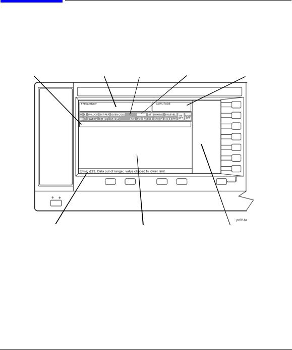
Front Panel Display
Figure 1-2 shows the front panel display. The LCD screen displays data fields, annotations, key press results, softkey labels, error messages, and annunciators that represent various active signal generator functions.
Figure 1-2 |
Front Panel Display Diagram |
|
|
|
|
|
|
4. Digital Modulation |
|
1. Active Entry Area |
2. Frequency Area |
3. Annunciators |
Annunciators |
5. Amplitude Area |
|
|
|||
6. Error Message Area |
7. Text Area |
8. Softkey Label Area |
1. Active Entry Area
The current active function is shown in this area. For example, if frequency is the active function, the current frequency setting will be displayed here. If the current active function has an increment value associated with it, that value is also displayed.
2. Frequency Area
The current frequency setting is shown in this portion of the display. Indicators are also displayed in this area when the frequency offset or multiplier is used, the frequency reference mode is turned on, or a source module is enabled.
Chapter 1 |
13 |
Signal Generator Overview
Front Panel Display
3. Annunciators
The display annunciators show the status of some of the signal generator functions and indicate any error conditions. An annunciator position may be used by more than one function. This does not create a problem, because only one function that shares an annunciator position can be active at a time.
Φ M |
This annunciator (E8257C and E8267C only) appears when phase modulation is on. If |
|
frequency modulation is on, the FM annunciator replaces Φ M. |
ALC OFF |
This annunciator appears when the ALC circuit is disabled. A second annunciator, |
|
UNLEVEL, appears in the same position if the ALC is enabled and cannot maintain the |
|
output level. |
AM |
This annunciator (E8257C and E8267C only) appears when amplitude modulation is on. |
ARMED |
This annunciator appears when a sweep has been initiated and the signal generator is |
|
waiting for the sweep trigger event. |
ATTEN HOLD |
This annunciator (Option 1E1 or E8267C only) appears when the attenuator hold |
|
function is on. When this function is on, the attenuator is held at its current setting. |
DIG BUS |
This annunciator appears when the Digital Bus is active, and the internal oven reference |
|
oscillator is not cold (they appear in the same location). |
ENVLP |
This annunciator appears if a burst condition exists, such as when marker 2 is set to |
|
enable RF blanking in the Dual ARB format. |
ERR |
This annunciator appears when an error message is in the error queue. This annunciator |
|
does not turn off until you either view all the error messages or cleared the error queue. |
|
To access error messages, press Utility > Error Info. |
EXT |
This annunciator appears when external leveling is on. |
EXT1 LO/HI |
This annunciator (E8257C and E8267C only) appears as either EXT1 LO or EXT1 HI, |
|
when the ac-coupled signal to the EXT 1 INPUT is <0.97 Vp or >1.03 Vp. |
EXT2 LO/HI |
This annunciator (E8257C and E8267C only) is displayed as either EXT2 LO or |
|
EXT2 HI. This annunciator appears when the ac-coupled signal to the EXT 2 INPUT is |
|
<0.97 Vp or >1.03 Vp. |
EXT REF |
This annunciator appears when an external frequency reference is applied. |
FM |
This annunciator (E8257C and E8267C only) appears when frequency modulation is |
|
turned on. If phase modulation is turned on, the Φ M annunciator will replace FM. |
I/Q |
This annunciator (E8267C with Option 002/602 only) appears when I/Q modulation is |
|
turned on. |
L |
This annunciator appears when the signal generator is in listener mode and is receiving |
|
information or commands over the RS-232, GPIB, or VXI-11 LAN interface. |
|
|
14 |
Chapter 1 |
|
Signal Generator Overview |
|
Front Panel Display |
MOD ON/OFF |
This annunciator (E8257C and E8267C only) which is always present on the display, |
|
indicates whether active modulation formats have been enabled or disabled with the |
|
Mod On/Off hardkey. Pressing the Mod On/Off hardkey enables or disables all active |
|
modulation formats (AM, FM, Φ M, Pulse, or I/Q) that are applied to the output carrier |
|
signal available through the RF Output connector. The Mod On/Off hardkey does not set |
|
up or activate an AM, FM, Φ M, Pulse, or I/Q format; each individual modulation |
|
format must still be set up and activated (for example, AM > AM On) or nothing will be |
|
applied to the output carrier signal when the Mod On/Off hardkey is enabled. |
OVEN COLD |
This annunciator (Option UNR only) appears when the temperature of the internal oven |
|
reference oscillator has dropped below an acceptable level. When this annunciator is on, |
|
frequency accuracy is degraded. This condition should occur only if the signal generator |
|
is disconnected from line power. |
PULSE |
This annunciator (E8257C and E8267C only) appears when pulse modulation is on. |
R |
This annunciator appears when the signal generator is remotely controlled over the |
|
GPIB, RS-232, or VXI-11/Sockets LAN interface (TELNET operation does not activate |
|
the R annunciator). When the R annunciator is on, the front panel keys are disabled, |
|
except for the Local key and the line power switch. For information on remote |
|
operation, refer to the Programming Guide. |
RF ON/OFF |
This annunciator indicates when the RF and microwave signal is present (RF ON) at the |
|
RF OUTPUT, or if the RF and microwave signal is not present (RF OFF) at the RF |
|
OUTPUT. Either condition of this annunciator is always visible in the display. |
S |
This annunciator appears when the signal generator has generated a service request |
|
(SRQ) over the RS-232, GPIB, or VXI-11 LAN interface. |
SWEEP |
This annunciator appears when the signal generator is in list, step, or ramp sweep mode; |
|
ramp sweep is available with Option 007 only. List mode is when the signal generator |
|
can jump from point to point in a list (hop list); the list is traversed in ascending or |
|
descending order. The list can be a frequency list, a power level list, or both. Step mode |
|
is when a start, stop, and step value (frequency or power level) are defined and the |
|
signal generator produces signals that start at the start value and increment by the step |
|
value until it reaches the stop value. Ramp sweep mode (Option 007 only) is when a |
|
start and stop value (frequency or power level) are defined and the signal generator |
|
produces signals that start at the start value and produce a continuous output until it |
|
reaches the stop value. |
T |
This annunciator appears when the signal generator is in talker mode and is transmitting |
|
information over the GPIB, RS-232, or VXI-11 LAN interface. |
UNLEVEL |
This annunciator appears when the signal generator is unable to maintain the correct |
|
output level. The UNLEVEL annunciator is not necessarily an indication of instrument |
|
failure. Unleveled conditions can occur during normal operation. A second annunciator, |
|
ALC OFF, will appear in the same position when the ALC circuit is disabled. |
|
|
Chapter 1 |
15 |

Signal Generator Overview
Front Panel Display
UNLOCK |
This annunciator appears when any of the phase locked loops are unable to maintain |
|
phase lock. You can determine which loop is unlocked by examining the error |
|
messages. |
4. Digital Modulation Annunciators
All digital modulation annunciators (E8267C PSG with Option 002/602 only) appear in this location. These annunciators appear only when the modulation is active, and only one digital modulation can be active at any given time.
ARB |
Dual Arbitrary Waveform Generator |
M-TONE |
Multitone Waveform Generator |
CUSTOM |
Custom Real Time I/Q Baseband |
T-TONE |
Two-Tone Waveform Generator |
DIGMOD |
Custom Arb Waveform Generator |
|
|
5. Amplitude Area
The current output power level setting is shown in this portion of the display. Indicators are also displayed in this area when amplitude offset is used, amplitude reference mode is turned on, external leveling mode is enabled, a source module is enabled, and when user flatness is enabled.
6. Error Message Area
Abbreviated error messages are reported in this space. When multiple error messages occur, only the most recent message remains displayed. Reported error messages with details can be viewed by pressing Utility >
Error Info.
7. Text Area
This text area of the display:
•show signal generator status information, such as the modulation status, sweep lists, and file catalogs
•displays the tables
•enables you to perform functions such as managing information, entering information, and displaying or deleting files
8. Softkey Label Area
The labels in this area define the function of the softkeys located immediately to the right of the label. The
softkey label may change depending upon the function selected.
16 |
Chapter 1 |

Signal Generator Overview
Rear Panel
Rear Panel
The signal generator rear panel (Figure 1-3) provides input, output, and remote interface connections. Descriptions are provided for each rear panel connector. When Option 1EM is added, all front panel connectors are moved to the real panel; for a description of these connectors, see “Front Panel” on page 6.
Figure 1-3 |
Rear Panel Diagram |
|
|
|
|
|
|
|
|
|||||||||||||||||||||||||||||
16. Digital Bus |
|
|
|
|
|
|
|
|
17. WIDEBAND I INPUT |
|
|
|
|
|
|
|
|
|||||||||||||||||||||
15. AUXILIARY I/O |
|
|
|
|
|
|
|
|
|
|
18. WIDEBAND Q INPUT |
|
|
|
|
|
|
20. I OUT |
||||||||||||||||||||
|
|
|
|
|
|
|
|
|
|
|
|
|
|
|
|
|
|
|
|
|
|
|
|
|
|
|
|
|
|
|
|
|
21. |
I-bar OUT |
||||
|
|
|
|
|
|
|
|
|
|
|
|
|
|
|
|
|
|
|
|
|
|
19. COH |
|
|
|
|
|
|
|
|
|
22. Q OUT |
||||||
|
|
|
|
|
|
|
|
|
|
|
|
|
|
|
|
|
|
|
|
|
|
|
|
|
|
|
|
|
|
|
|
|||||||
|
|
|
|
|
|
|
|
|
|
|
|
|
|
|
|
|
|
|
|
|
|
|
|
|
|
|
|
|
|
|
|
|
|
|
23. |
Q-bar OUT |
||
|
|
|
|
|
|
|
|
|
|
|
|
|
|
|
|
|
|
|
|
|
|
|
|
|
|
|
|
|
|
|
|
|
|
|
|
|
24. BASEBAND GEN |
|
|
|
|
|
|
|
|
|
|
|
|
|
|
|
|
|
|
|
|
|
|
|
|
|
|
|
|
|
|
|
|
|
|
|
|
|
|
25. SMI |
|
|
|
|
|
|
|
|
|
|
|
|
|
|
|
|
|
|
|
|
|
|
|
|
|
|
|
|
|
|
|
|
|
|
|
|
|
|
26. 10 MHz OUT |
|
|
|
|
|
|
|
|
|
|
|
|
|
|
|
|
|
|
|
|
|
|
|
|
|
|
|
|
|
|
|
|
|
|
|
27. |
10 MHz IN |
|||
|
|
|
|
|
|
|
|
|
|
|
|
|
|
|
|
|
|
|
|
|
|
|
|
|
|
|
|
|
|
|
|
|
|
|
|
|
28. 10 MHz EFC |
|
|
|
|
|
|
|
|
|
|
|
|
|
|
|
|
|
|
|
|
|
|
|
|
|
|
|
|
|
|
|
|
|
|
|
|
||||
|
|
|
|
|
|
|
|
|
|
|
|
|
|
|
|
|
|
|
|
|
|
|
|
|
|
|
|
|
|
|
|
|
|
|
|
|
(Option UNR) |
|
|
|
|
|
|
|
|
|
|
|
|
|
|
|
|
|
|
|
|
|
|
|
|
|
|
|
|
|
|
|
|
|
|
|
|
|
|
|
|
|
|
|
|
|
|
|
|
|
|
|
|
|
|
|
|
|
|
|
|
|
|
|
|
|
|
|
|
|
|
|
|
|
|
|
|
|
|
|
|
|
|
|
|
|
|
|
|
|
|
|
|
|
|
|
|
|
|
|
|
|
|
|
|
|
|
|
|
|
|
|
|
|
|
|
|
|
|
1. AC Power Receptacle
2. GPIB
3. AUXILIARY INTERFACE
4. LAN
14.BURST GATE IN
13.PATTERN TRIG
12.EVENT 2
11. EVENT 1 |
|
|
|
|
|
|
|
5. STOP SWEEP IN/OUT |
|
|
|
|
|
|
|
|
|||
|
|
|
|
|
|
|
|
|
6. Z-AXIS BLANK/MKRS |
|
|
|
|
|
|
|
|
|
|
|
|
|
|
|
|
|
|
|
7. SWEEP OUT |
|
|
|
|
|
|
|
|
|
|
|
|
|
|
|
|
|
|
|
8. TRIGGER OUT |
|
|
|
|
|
|
|
|
||
|
|
|
|
|
|
|
|
|
9. TRIGGER IN |
|
|
|
|
|
|
|
|||
|
|
|
|
|
|
|
|
|
10. SOURCE SETTLED |
|
|
|
|
|
|
|
|
|
|
Chapter 1 |
17 |

Signal Generator Overview
Rear Panel
1. AC Power Receptacle
The ac line voltage is connected here. The power cord receptacle accepts a three-pronged power cable that is shipped with the signal generator.
2. GPIB
This GPIB interface allows listen and talk capability with compatible IEEE 488.2 devices.
3. AUXILIARY INTERFACE
This 9-pin D-subminiature female connector is an RS-232 serial port that can be used for serial communication and Master/Slave source synchronization.
Table 1-3 |
Auxiliary Interface Connector |
|
|
|
|
Pin Number |
Signal Description |
Signal Name |
|
|
|
1 |
No Connection |
|
|
|
|
2 |
Receive Data |
RECV |
|
|
|
3 |
Transmit Data |
XMIT |
|
|
|
4 |
+5V |
|
|
|
|
5 |
Ground, 0V |
|
|
|
|
6 |
No Connection |
|
|
|
|
7 |
Request to Send |
RTS |
|
|
|
8 |
Clear to Send |
CTS |
|
|
|
9 |
No Connection |
|
|
|
|
Figure 1-4
View looking into rear panel connector
4. LAN
This LAN interface allows ethernet local area network communication through a 10Base-T LAN cable. The yellow LED on the interface illuminates when data transmission (transfer/receive) is present. The green LED illuminates when there is a delay in data transmission or no data transmission is present.
18 |
Chapter 1 |

Signal Generator Overview
Rear Panel
5. STOP SWEEP IN/OUT
This female BNC connector (Option 007 only) provides an open-collector, TTL-compatible input/output signal that is used during ramp sweep operation. It provides low level (nominally 0V) output during sweep retrace and band-cross intervals. It provides high level (nominally +5V) output during the forward portion of sweep. Sweep stops when this input/output connector is grounded externally.
6. Z-AXIS BLANK/MKRS
This female BNC connector (Option 007 only) supplies a +5V (nominal) level during retrace and band-switch intervals of a step, list, or ramp sweep. During ramp sweep, this female BNC connector supplies a –5V (nominal) level when the RF frequency is at a marker frequency and intensity marker mode is on. This connection is most commonly used to interface with an Agilent 8757D scalar network analyzer.
7. SWEEP OUT
This female BNC connector outputs a voltage proportional to the RF power or frequency sweep ranging from 0 V at the start of sweep and goes to +10 V (nominal) at the end of sweep, regardless of sweep width.
The output impedance is less than 1Ω and can drive a 2 kΩ load.
When connected to an Agilent Technologies 8757D network analyzer, it generates a selectable number of equally spaced 1 ms 10 V pulses (nominal) across a ramp (analog) sweep. The number of pulses can be set from 101 to 1601 by remote control through the 8757D.
8. TRIGGER OUT
This female BNC connector, in step/list sweep mode, outputs a TTL signal that is high at the start of a dwell sequence or when waiting for a point trigger in manual sweep mode. The signal is low when the dwell is over or when a point trigger is received. In ramp sweep mode, the output provides 1601 equally-spaced 1 µs pulses (nominal) across a ramp sweep. When using LF Out, the output provides a 2 µs pulse at the start of LF sweep.
9. TRIGGER IN
This female BNC connector accepts a 3.3V CMOS signal that is used for point-to-point triggering in manual sweep mode or a low-frequency (LF) sweep in external sweep mode. Triggering can occur on either the positive or negative edge of the signal start. The damage level is ≤ −4 V or ≥ + 10 V.
10. SOURCE SETTLED
This female BNC connector provides an indication when the signal generator has settled to a new frequency or power level. A low indicates that the source has settled.
Chapter 1 |
19 |

Signal Generator Overview
Rear Panel
11. EVENT 1
This female BNC connector (E8267C only) is used with an internal baseband generator (Option 002/602); on signal generators without Option 002/602, this female BNC connector is non-functional.
In real-time mode, the EVENT 1 connector outputs a pattern or frame synchronization pulse for triggering or gating external equipment. It may be set to start at the beginning of a pattern, frame, or timeslot and is adjustable to within ± one timeslot with one bit resolution.
In arbitrary waveform mode, the EVENT 1 connector outputs a timing signal generated by Marker 1.
A marker (3.3V CMOS high when positive polarity is selected; 3.3V CMOS low when negative polarity is selected) is output on the EVENT 1 connector whenever a Marker 1 is turned on in the waveform. The damage levels for this connector are > +8V and < −4V.
12. EVENT 2
This female BNC connector (E8267C only) is used with an internal baseband generator (Option 002/602); on signal generators without Option 002/602, this female BNC connector is non-functional. In real-time mode, the EVENT 2 connector outputs a data enable signal for gating external equipment. This is applicable when external data is clocked into internally generated timeslots.
Data is enabled when the signal is low. In arbitrary waveform mode, the EVENT 2 connector outputs a timing signal generated by Marker 2. A marker (3.3V CMOS high when positive polarity is selected; 3.3V CMOS low when negative polarity is selected) is output on the EVENT 2 connector whenever a Marker 2 is turned on in the waveform. The damage levels for this connector are > +8V and < −4V.
13. PATTERN TRIG IN
This female BNC connector (E8267C only) is used with an internal baseband generator (Option 002/602); on signal generators without Option 002/602, this female BNC connector is non-functional. This connector accepts a signal that triggers an internal pattern or frame generator to start single pattern output. Minimum pulse width is 100 ns. Damage levels are > +5.5 and < −0.5V.
14. BURST GATE IN
This female BNC connector (E8267C only) is used with an internal baseband generator (Option 002/602); on signal generators without Option 002/602, this female BNC connector is non-functional. This connector accepts a signal for gating burst power. Burst gating is used when you are externally supplying data and clock information.
The input signal must be synchronized with the external data input that will be output during the burst. The burst power envelope and modulated data are internally delayed and re-synchronized. The input signal must be CMOS high for normal burst RF power or CW RF output power and CMOS low for RF off. Damage levels are > +5.5 and < −0.5V.
20 |
Chapter 1 |
Loading...