


35670-90066

Agilent 35670A Service Guide
Agilent Part Number 35670-90066
Printed in Malaysia
Print Date: March 2001
Copyright © Agilent Technologies, Inc., 1992-1995,2000, 2001.
All rights reserved.
8600 Soper Hill Road Everett, Washington 98205-1209 U.S.A.
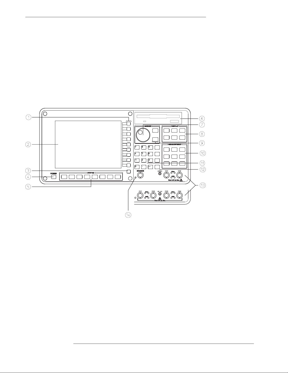
The Agilent 35670A at a Glance (Front Panel)

Agilent 35670A Front Panel
1-Use the softkeys to select items from the current menu. A softkey’s function is indicated by a video label on the analyzer’s screen.
Throughout this book, softkeys are printed like this: [
Hardkeys are front-panel buttons whose functions are always the same. They have a label printed directly on the key itself.
Throughout this book, hardkeys are printed like this: [
FFT ANALYSIS
Inst Mode
].
].
2-The analyzer’s screen is divided into the menu area and the display area. The menu area displays video labels for the softkeys. The
data area displays measurement data and information about the parameter settings.
3-The [
] key returns the menu to the previous level.
Rtn
4-The POWER switch turns on the analyzer.
5-Use the SYSTEM keys to control various system-level functions. These functions include saving files, plotting measurement data,
and accessing online help.
6-Use the disk drive to save your work on 3.5 inch flexible disks.
7-The knob moves the markers and the cursor. It also steps through numeric values and scrolls through online help.
8-Use the DISPLAY keys to control what appears on the analyzer’s traces. They only affect how data is displayed; DISPLAY keys
do not change measurement parameters.
You can press keys in the DISPLAY menus without losing measurement parameters.
9-Use the MARKER keys to select a variety of marker features.
10-Use the MEASUREMENT keys to control the analyzer’s source and inputs. They also control measurement parameters. You
must make a new measurement if you change a MEASUREMENT parameter.
11-Use the numeric-entry keys to enter a numeric value.
12-The microphone power connector provides power (8 Vdc) for the Microphone Adapter Kit (Option UK4).
13-The connector area of the front panel has two different configurations. The standard analyzer has a source output connector and
two input connectors. The 4-channel analyzer (Option AY6) has four input connectors.
Range indicators are located next to each input connector. The upper LED is the over-range indicator (the signal level exceeds the
current range setting). The lower LED is the half range indicator (the signal level exceeds half the current range setting).
14-A source on/off indicator is located at the left edge of the connector area.
The standard Agilent 35670A (2-channel) has a source connector on the front panel.
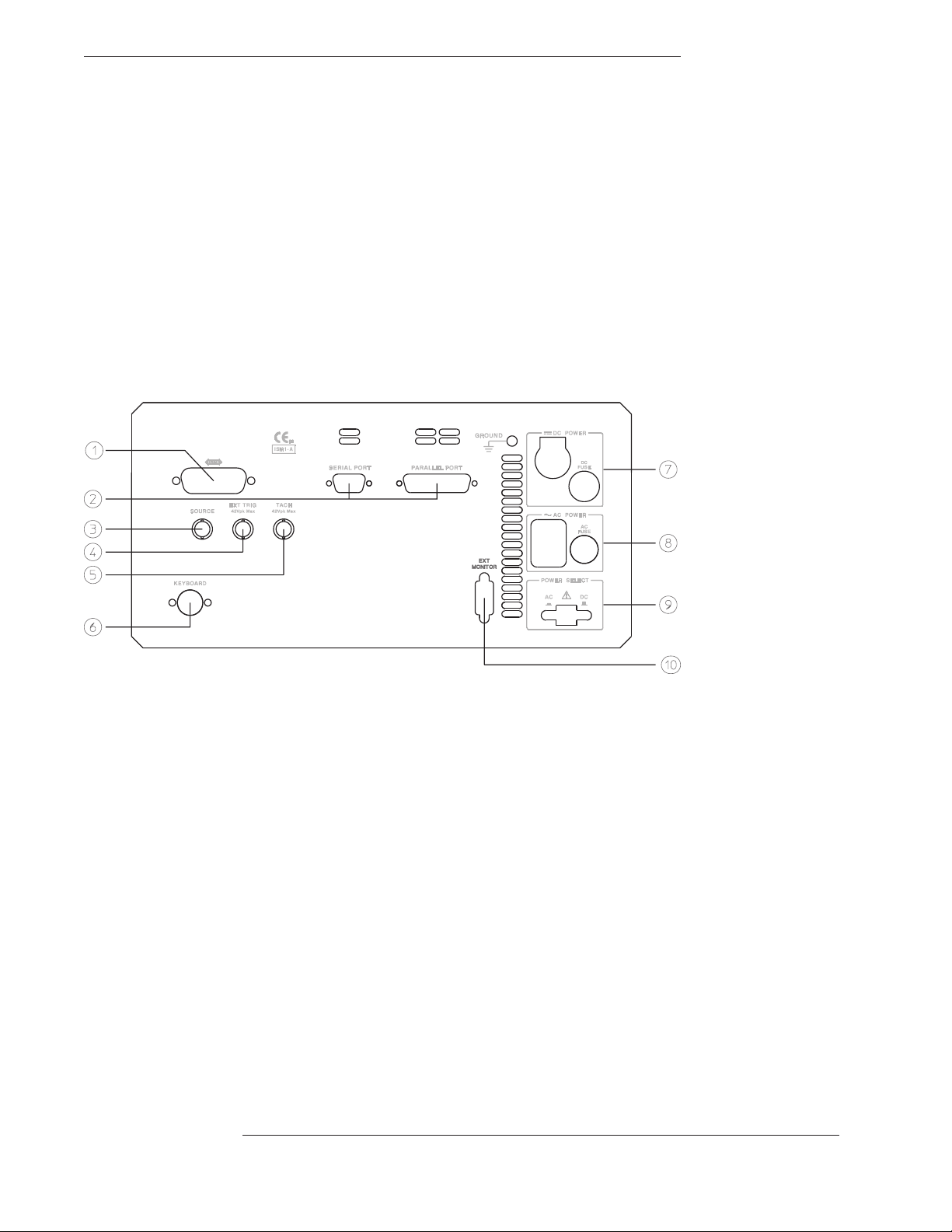
The Agilent 35670A at a Glance (Rear Panel)

Agilent 35670A Rear Panel
1-The GPIB connector links the Agilent 35670A to other GPIB devices. GPIB parameters are set in the [
[
Plot/Print
] menus.
Local/GPIB
] and
2-The SERIAL PORT and the PARALLEL PORT link the analyzer to plotters and printers. These parameters are set in the
[
Plot/Print
] menu.
3-The SOURCE connector outputs the analyzer’s source signal. An LED on the front panel indicates if the source is on or off. The
source parameters are set in the [
The standard Agilent 35670A (2-channel) also has a source connector on the front panel.
4-The EXT TRIG connector links the analyzer to an external trigger signal. The external trigger parameters are set in the [
menu.
5-The TACH connector links the analyzer to a tachometer. The tachometer parameters are set in the [
Source
] menu.
Input
Trigger
] menu.
6-The KEYBOARD connector attaches an optional keyboard to the analyzer.
7-The DC POWER connector accepts DC power levels from 12 - 28 Vdc (nominal).
8-The AC POWER connector accept a wide range of ac voltage levels.
9-The POWER SELECT switch determines whether the analyzer is powered via the AC POWER connector or the DC POWER
connector.
10-The EXT MONITOR port links the analyzer to multi-sync monitors.
]

Saftey Summary
The following general safety precautions must be observed during all phases of
operation of this instrument. Failure to comply with these precautions or with
specific warnings elsewhere in this manual violates safety standards of design,
manufacture, and intended use of the instrument. Agilent Technologies, Inc.
assumes no liability for the customer’s failure to comply with these
requirements.
GENERAL
This product is a Safety Class 1 instrument (provided with a protective earth
terminal). The protective features of this product may be impaired if it is used in
a manner not specified in the operation instructions.
All Light Emitting Diodes (LEDs) used in this product are Class 1 LEDs as per
IEC 60825-1.
ENVIRONMENTAL CONDITIONS
This instrument is intended for indoor use in an installation category II, pollution
degree 2 environment. It is designed to operate at a maximum relative humidity
of 95% and at altitudes of up to 2000 meters. Refer to the specifications tables
for the ac mains voltage requirements and ambient operating temperature range.
BEFORE APPLYING POWER
Verify that the product is set to match the available line voltage, the correct fuse
is installed, and all safety precautions are taken. Note the instrument’s external
markings described under Safety Symbols.
GROUND THE INSTRUMENT
To minimize shock hazard, the instrument chassis and cover must be connected
to an electrical protective earth ground. The instrument must be connected to
the ac power mains through a grounded power cable, with the ground wire
firmly connected to an electrical ground (safety ground) at the power outlet.
Any interruption of the protective (grounding) conductor or disconnection of
the protective earth terminal will cause a potential shock hazard that could
result in personal injury.

FUSES
Only fuses with the required rated current, voltage, and specified type (normal
blow, time delay, etc.) should be used. Do not use repaired fuses or
short-circuited fuse holders. To do so could cause a shock or fire hazard.
DO NOT OPERATE IN AN EXPLOSIVE ATMOSPHERE
Do not operate the instrument in the presence of flammable gases or fumes.
DO NOT REMOVE THE INSTRUMENT COVER
Operating personnel must not remove instrument covers. Component
replacement and internal adjustments must be made only by qualified service
personnel.
Instruments that appear damaged or defective should be made inoperative and
secured against unintended operation until they can be repaired by qualified
service personnel.
WARNING The WARNING sign denotes a hazard. It calls attention to a procedure,
practice, or the like, which, if not correctly performed or adhered to,
could result in personal injury. Do not proceed beyond a WARNING
sign until the indicated conditions are fully understood and met.
Caution The CAUTION sign denotes a hazard. It calls attention to an operating
procedure, or the like, which, if not correctly performed or adhered to, could
result in damage to or destruction of part or all of the product. Do not proceed
beyond a CAUTION sign until the indicated conditions are fully understood and
met.
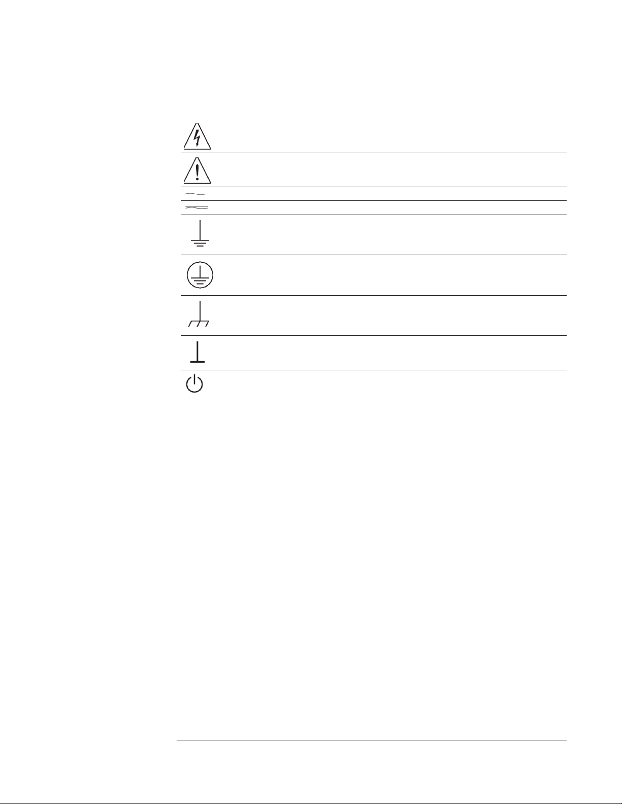
Safety Symbols
Warning, risk of electric shock
Caution, refer to accompanying documents
Alternating current
Both direct and alternating current
Earth (ground) terminal
Protective earth (ground) terminal
Frame or chassis terminal
Terminal is at earth potential.
Standby (supply). Units with this symbol are not completely disconnected from ac mains when
this switch is off

Accessories
The accessories listed in the following table are supplied with the
Agilent 35670A.
Supplied Accessories Part Number
Line Power Cable See page 2-4
Standard Data Format Utilities HP 5061-8042
Agilent 35670A Operator’s Guide Agilent 35670-90053
Agilent 35670A Quick Start Agilent 35670-90056
Agilent 35670A Installation and Verification Guide Agilent 35670-90054
Agilent 35670A GPIB Command Reference Agilent 35670-90057
GPIB Programmer’s Guide Agilent 5960-5708
Agilent 35670A GPIB Commands: Quick Reference Agilent 35670-90048
The accessories listed in the following table are available for the
Agilent 35670A.
Available Accessories Part Number
DC Power Cable, 3 meter HP 35250A
DC Power Cable with Cigarette Lighter Adapter HP 35251A
Box of ten 3.5-inch double-sided, double-density disks HP 92192A
Using Instrument BASIC with the Agilent 35670A Agilent 35670-90049
Instrument BASIC User’s Handbook HP E2083-90000
HP Thinkjet Printer HP 2225A
HP Quietjet Printer HP 2227A
HP Jet Paper, 2500 sheets HP 92261N
GPIB Cable, 1 meter HP 10833A
GPIB Cable, 2 meter HP 10833B
GPIB Cable, 4 meter HP 10833C
GPIB Cable, 0.5 meter HP 10833D

In This Book
This guide provides instructions for installing, verifying performance, and repairing
the Agilent 35670A Dynamic Signal Analyzer.
Chapter 1, ‘’Specifications,’’ lists the specifications for the Agilent 35670A and the
specifications for the required test equipment.
Chapter 2, ‘’Preparing the Analyzer for Use,’’ provides step-by-step instructions for
getting the analyzer ready to use and instructions on cleaning the screen, storing, and
transporting.
Chapter 3, ‘’Verifying Specifications,’’ provides step-by-step instructions for
installing and running the semiautomated performance test software. This chapter also
provides illustrations that show the equipment set up for each test and a copy of the
test records.
Chapter 4, ‘’Troubleshooting the Analyzer,’’ provides step-by-step instructions for
isolating most failures to the faulty assembly.
Chapter 5, ‘’Adjusting the Analyzer,’’ provides step-by-step instructions for adjusting
the analyzer.
Chapter 6, ‘’Replacing Assemblies,’’ provides step-by-step instructions to follow
before and after replacing an assembly. This chapter also provides step-by-step
instructions for disassembling the analyzer.
Chapter 7, ‘’Replaceable Parts,’’ provides ordering information and lists the
replaceable parts.
Chapter 8, ‘’Circuit Descriptions,’’ provides the overall instrument description and
individual assembly descriptions.
Chapter 9, ‘’Voltages and Signals,’’ shows where the signals and voltages are used in
the analyzer and describes each signal.
Chapter 10, ‘’Internal Test Descriptions,’’ describes the power-on test, calibration
routine, fault log messages, and self tests.
Chapter 11, ‘’Backdating,’’ provides information necessary to modify this manual for
instruments that differ from those currently being produced.
Chapter 12, ‘’Quick Reference,’’ shows assembly locations, cable connections, and all
the block diagrams.

Table of Contents
1 Specifications
Frequency 1-3
Single Channel Amplitude 1-4
FFT Dynamic Range 1-5
Input Noise 1-6
Window Parameters 1-6
Single Channel Phase 1-6
Cross Channel Amplitude 1-7
Cross Channel Phase 1-7
Input 1-8
Time Domain 1-9
Trigger 1-9
Tachometer 1-10
Source Output 1-11
Digital Interfaces 1-12
General Specifications 1-13
Order Tracking — Option 1D0 1-14
Swept Sine Measurements —Option 1D2 1-15
Arbitrary Waveform Source—Option 1D4 1-15
Real Time Octave Analysis — Option 1D1 1-16
Recommended Test Equipment 1-17

2 Preparing the Analyzer for Use
To do the incoming inspection 2-5
To install the analyzer 2-7
To connect the analyzer to a dc power source 2-8
To change the fuses 2-10
To connect the analyzer to a serial device 2-11
To connect the analyzer to a parallel device 2-11
To connect the analyzer to an GPIB device 2-12
To connect the analyzer to an external monitor 2-13
To connect the optional keyboard 2-14
To connect the microphone adapter 2-16
To clean the screen 2-17
To store the analyzer 2-17
To transport the analyzer 2-18
If the analyzer will not power up 2-19
If the analyzer operates intermittently on dc power 2-20
3 Verifying Specifications
To load the program 3-7
To run the program in semiautomated mode 3-8
To run the program without a printer 3-10
To run the program in manual mode 3-12
To set up the self test 3-13
To set up the dc offset test 3-14
To set up the noise test 3-15
To set up the spurious signals test 3-16
To set up the amplitude accuracy test 3-17
To set up the flatness test 3-18
To set up the amplitude linearity test 3-19
To set up the A-weight filter test 3-20
To set up the channel match test 3-21
To set up the frequency accuracy test 3-22

To set up the anti-alias filter test 3-23
To set up the input coupling test 3-24
To set up the harmonic distortion test 3-25
To set up the intermodulation distortion test 3-28
To set up the cross talk test 3-30
To set up the single channel phase accuracy test 3-34
To set up the external trigger test 3-35
To set up the tach function test 3-37
To set up the input resistance test 3-39
To set up the ICP supply test 3-41
To set up the source amplitude accuracy test 3-45
To set up the source output resistance test 3-46
To set up the source dc offset test 3-48
To set up the source flatness test 3-49
To set up the source distortion test 3-50
Measurement Uncertainty 3-56
Performance Test Record - Two Channel 1 of 14
Performance Test Record - Four Channel 1 of 20
Operation Verification Test Record - Two Channel 1 of 10
Operation Verification Test Record - Four Channel 1 of 15

4 Troubleshooting the Analyzer
How to troubleshoot the analyzer 4-4
To perform initial verification 4-5
To troubleshoot the power supply 4-11
To troubleshoot power-up failures 4-15
To troubleshoot CPU, memory, and buses failures 4-18
To troubleshoot display failures 4-22
To troubleshoot IIC bus failures 4-25
To troubleshoot fast bus failures 4-29
To perform self tests 4-31
To troubleshoot self-test lockup failures 4-37
To troubleshoot intermittent failures 4-40
To troubleshoot performance test failures 4-42
To troubleshoot source and calibrator failures 4-45
To troubleshoot input and ADC failures 4-51
To troubleshoot input failures on four channel analyzers 4-54
To troubleshoot distortion failures 4-56
To troubleshoot disk drive failures 4-57
To troubleshoot auto-range failures 4-59
To troubleshoot DIN connector failures 4-61
To troubleshoot trigger failures 4-62
To troubleshoot memory battery failures 4-67
To troubleshoot microphone power and adapter failures 4-69
To troubleshoot tachometer failures 4-70

5 Adjusting the Analyzer
To adjust the frequency reference 5-5
To adjust the source 5-6
To adjust the ADC gain, offset and reference 5-7
To adjust the input dc offset 5-10
To adjust common mode rejection 5-13
To adjust filter flatness 5-17
To adjust the display voltage 5-21
6 Replacing Assemblies
What to do before replacing the CPU assembly 6-3
What to do after replacing an assembly 6-4
To remove cover 6-6
To remove rear panel 6-7
To remove front panel 6-8
To remove disk drive 6-10
To remove CPU 6-11
To remove NVRAM 6-12
To remove memory 6-13
To remove power supply 6-14
To remove motherboard 6-16
To remove dc-dc converter 6-18

7 Replaceable Parts
Ordering Information 7-2
Assemblies 7-4
Cables 7-6
Instrument Covers and Handles 7-7
Assembly Covers and Brackets 7-8
Front Panel Parts 7-9
Rear Panel Parts 7-10
Chassis Parts 7-11
Screws, Washers, and Nuts 7-12
Miscellaneous Parts 7-12
Option UK4 Parts 7-13

8 Circuit Descriptions
Overall Instrument Description 8-2
A1 Input 8-6
A2 Input 8-12
A5 Analog 8-18
A6 Digital 8-22
A7 CPU 8-25
A8 Memory 8-30
A9 NVRAM 8-32
A10 Rear Panel 8-33
A11 Keyboard Controller 8-35
A12 BNC 8-36
A13 Primary Keypad 8-37
A14 Secondary Keypad 8-37
A15 Primary Keypad 8-37
A22 BNC 8-37
A90 Fan 8-38
A98 Power Supply 8-38
A99 Motherboard 8-39
A100 Disk Drive 8-39
A101 Display 8-39
A102 DC-DC Converter 8-39
Option UK4 Microphone Adapter and Power Supply 8-40

9 Voltages and Signals
Assembly Locations and Connections 9-3
Power Supply Voltage Distribution 9-6
A1 Input 9-7
A2 Input 9-7
A8 Memory 9-8
A9 NVRAM 9-12
A10 Rear Panel 9-14
A11 Keyboard Controller 9-18
A12 BNC 9-20
A13 Primary Keypad 9-21
A14 Secondary Keypad 9-23
A22 BNC 9-24
A99 Motherboard 9-25
A100 Disk Drive 9-34
A101 Display 9-36
A102 DC-DC Converter 9-37
10 Internal Test Descriptions
Power-on Test Description 10-2
Calibration Routine Description 10-5
Fault Log Messages 10-9
Self-Test Descriptions 10-10
11 Backdating
12 Quick Reference
Index
Guide to Agilent 35670A Documentation
Need Assistance?

1
Specifications
1-1

Specifications
This chapter contains the specifications for the Agilent 35670A Dynamic
Signal Analyzer and the critical specifications for the equipment required to
test the Agilent 35670A.
Instrument specifications apply after 15 minutes warm-up and within 2 hours of
the last self-calibration. When the internal cooling fan has been turned OFF,
specifications apply within 5 minutes of the last self-calibration. All
specifications are with 400 line frequency resolution unless stated otherwise.
Four channel instruments are unspecified in the one channel mode where alias
protection filters are not connected.
Abbreviations
dBVrms = dB relative to 1 Volt rms.
dBfs = dB relative to full scale amplitude range. Full scale is approximately 2 dB below ADC
overload.
FS or fs Full scale; synonymous with input range.
Real Time or Online = Refer to the collecting and displaying of information with no dropouts
or missing information.
Rload = Load resistance connected to the analyzer’s source.
Typical = Typical, non-warranted, performance specification included to provide general
product information.
Vpk = Peak of the ac voltage.
1-2

Agilent 35670A Specifications
Frequency
Frequency
Maximum range
1 channel mode
2 channel mode
4 channel mode (option AY6 only)
Spans
1 channel mode
2 channel mode
4 channel mode (option AY6 only)
Minimum resolution
1 channel mode
2 channel mode
4 channel mode (option AY6 only)
Maximum real-time bandwidth (FFT span for continuous data acquistion) (preset, fast averaging)
1 channel mode
2 channel mode
4 channel mode (option AY6 only)
Measurement rate (typical) (preset, fast averaging)
1 channel mode
2 channel mode
4 channel mode (option AY6 only)
Display update rate (typical)
(preset, fast average off)
102.4 kHz, 51.2 kHz (option AY6†)
51.2 kHz
25.6 kHz
195.3 mHz to 102.4 kHz
97.7 mHz to 51.2 kHz
48.8 mHz to 25.6 kHz
122 mHz (1600 line display)
61 mHz (1600 line display)
61 mHz (800 line display)
25.6 kHz
12.8 kHz
6.4 kHz
≥70 averages/second (≥170 with 100 line display)
≥33 averages/second
≥15 averages/second
5 updates/second
9 updates/second (single channel, single display,
undisplayed traces set with static data: e.g., data
register)
Accuracy
† Option AY6 single channel maximum range extends to 102.4 kHz without anti-alias filter protection.
±30 ppm (±0.003%)
1-3

Specifications Agilent 35670A
Single Channel Amplitude
Single Channel Amplitude
Absolute amplitude accuracy (FFT)
(A combination of full scale accuracy, full
scale flatness, and amplitude linearity.)
FFT full scale accuracy at 1 kHz (0 dBfs)
FFT full scale flatness (0 dBfs) relative to 1
kHz
FFT amplitude linearity at 1 kHz
Measured on +27 dBVrms range with time
average, 0 to −80 dBfs.
Amplitude resolution (16 bits less 2 dB over-range)
with averaging
Residual dc response
FFT mode frequency display
(excludes A-weight filter)
±2.92% (0.25 dB) of reading
±0.025% of full scale
±0.15 dB (1.74%)
±0.2 dB (2.33%)
±0.58% (0.05 dB) of reading
±0.025% of full scale
0.0019% of full scale (typical)
<−30 dBfs or -66dBVdc (0.5 mVdc) (whichever is
greater)
1-4
Agilent 35670A Specifications
FFT Dynamic Range
FFT Dynamic Range
Spurious free dynamic range
(Includes spurs, harmonic distortion,
intermodulation distortion, alias products)
Excludes alias responses at extremes of span.
Source impedance = 50 Ω
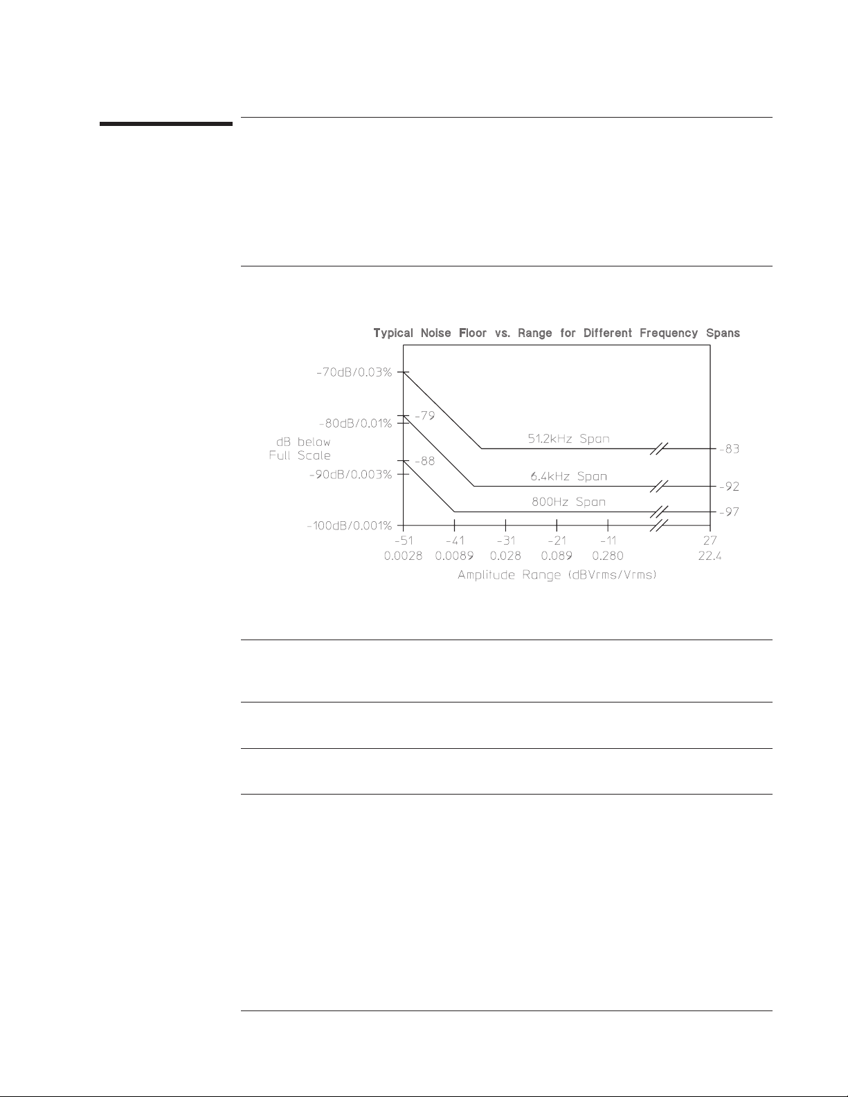
FFT noise floor (typical)
Flat top window, 64 RMS averages
<−80 dBfs (90 dB typical)
Harmonic distortion
Single tone (in band), ≤0 dBfs
Post-filter harmonic distortion (alias
responses) of a single tone ≤102.4 kHz, ≤0
dBfs
Intermodulation distortion
Two tones (in-band), each ≤−6.02 dBfs
Spurious and residual responses
Source impedance = 50 Ω
Frequency alias responses
Single tone (out of displayed range),
≤0 dBfs, ≤1 MHz (≤200 kHz with ICP on)
2.5% to 97.5% of the frequency span
Lower and upper 2.5% of frequency span
<−80 dBfs
<−80 dBfs
<−80 dBfs
<−80 dBfs
<−80 dBfs
<−65 dBfs
1-5

Specifications Agilent 35670A
Input Noise
Input Noise
Input noise level
Flat top window, −51 dBVrms range, source impedance = 50 Ω, 32 rms averages
Above 1280 Hz
160 Hz to 1.28 kHz (6.4 kHz span)
Note: To calculate noise as dB below full scale:
Noise [dBfs] = Noise [dBVrms/
See ‘’Window Parameters,’’ below, for noise equivalent bandwidths (NEBW).
] + 10LOG(NEBW) – Range [dBVrms].
Hz
<–140 dBVrms/√—Hz
<–130 dBVrms/√—Hz<%0 >
Window Parameters
Uniform Hann Flat Top
−3 dB bandwidth †
Noise equivalent bandwidth †
Attenuation at ± 1/2 bin
Shape factor (−60 dB BW/−3dBBW)
† For 800 line displays. With 400, 200, or 100 line displays, multiply bandwidths by 2, 4, and 8,
respectively. With 1600 line displays (only available in 1 or 2 channel mode), divide bandwidths by 2.
0.125% of span
0.125% of span
4.0 dB
716
0.185% of span
0.1875% of span
1.5 dB
9.1
0.450% of span
0.4775% of span
0.01 dB
2.6
Single Channel Phase
Phase accuracy relative to external trigger
16 RMS averages, center of bin, dc coupled,
0 dBfs to −50 dBfs, 0 Hz < freq ≤ 10.24 kHz only
For Hann and flat top windows, phase is referenced to a cosine wave at the center of the time
record. For the uniform, force, and exponential windows, phase is referenced to a cosine wave
at the beginning of the time record.
1-6
±4.0 degree

Agilent 35670A Specifications
Cross Channel Amplitude
Cross Channel Amplitude
FFT cross channel gain accuracy
Frequency response mode, same amplitude range
(AC coupled, Peroidic Chirp, Uniform Window, > =4Hz)
At full scale: Tested with 10 rms averages
on the −11 to +27 dBvrms ranges, and 100 rms
averages on the −51 dBVrms range
At −20 dBfs: Tested with 200 rms averages on
the −11 to +27 dBVrms ranges, and 2000 rms
averages on the −51 dBVrms range
Cross Channel Phase
Cross channel phase accuracy
(same conditions as cross-channel amplitude
>=12Hz)
±0.04 dB (0.46%)
±0.08 dB (0.92%)
±0.5 degree
1-7

Specifications Agilent 35670A
Input
Input
Input ranges
(full scale) (auto-range capability)
Maximum input levels 42 Vpk
Input impedance
Low side to chassis impedance
Floating mode
Grounded mode
AC coupling rolloff <3 dB rolloff at 1 Hz
Common mode rejection ratio
Single tone at or below 1 kHz
–51 dBVrms to –11 dBVrms ranges
–9 dBVrms to +9 dBVrms ranges
+11 dBVrms to +27 dBVrms ranges
Note: CM dBfs = CM signal input [dBVrms] − CMRR [dB] − range [dBVrms]
Common mode range (floating mode)
Amplitude over-range detection +3 dB typical
ICP signal conditioning
+27 dBVrms (31.7 Vpk) to −51 dBVrms
(3.99 mVpk) in 2 dB steps
1MΩ ±10%, 90 pF nominal
1MΩ ±30%, <0.010 µF (typical)
≤100 Ω
>75 dB typical
>60 dB typical
>40 dB typical
±4 Vpk
Current source
Open circuit voltage
A-weight filter
Conforms to ANSI Standard S1.4-1983; and
to IEC 651-1979; 10 Hz to 25.6 kHz
Crosstalk
Between input channels, and source-to-input
(receiving channel source impedance = 50 Ω)
4.25 ±1.5 mA
+26 to +32 Vdc
Type 0 Tolerance
<–135 dB below signal or <–80 dBfs of
receiving channel, whichever response is
greater in amplitude
1-8

Agilent 35670A Specifications
Time Domain
Time Domain
Specifications apply in histogram/time mode, unfiltered time display
DC amplitude accuracy
Rise time of −1 V to 0 V test pulse
Settling time of −1 V to 0 V test pulse
Pulse aberrations (peak overshoot)
of −1 V to 0 V test pulse
Peak aberration relative to the mode-to-mode
difference (most common values)
Sampling period
1 channel mode
2 channel mode
4 channel mode (option AY6 only)
±5.0%fs
<11.4 ms
<16 ms to 1%
<3 %
3.815 ms (1/262144 Hz) to2sin2× steps
7.629 ms (1/131072 Hz) to4sin2× steps
15.26 ms (1/65536 Hz) to8sin2× steps
Trigger
Trigger modes Internal trigger
External trigger
Source trigger
GPIB trigger
Maximum trigger delay
Post trigger
Pre trigger
No two channels can be further than ±7168 samples
from each other.
External trigger maximum input
External trigger range
Low range
High range
External trigger resolution
Low range
High range
8191 seconds
8191 sample periods
±42 Vpk
−2Vto+2V
−10 V to +10 V
15.7 mV
78 mV
1-9

Specifications Agilent 35670A
Tachometer
Tachometer
Pulses per revolution 0.5 to 2048
RPM accuracy
Tachometer level range
Low range
High range
Tachometer level resolution
Low range
High range
Tachometer level accuracy (as a % of
tachometer range setting)
Maximum tachometer input level
Minimum tachometer pulse width 600 ns
Maximum tachometer pulse rate 400 kHz
±100 ppm (0.01%) (typical)
–4Vto+4V
–20 V to +20 V
100 mV
500 mV
±10% of range
±42 Vpk
1-10

Agilent 35670A Specifications
Source Output
Source Output
Source types Sine, random noise, chirp, pink noise, burst
random, burst chirp
Amplitude range
AC amplitude resolution
Voltage ≥ 0.2 Vrms
Voltage < 0.2 Vrms
DC offset accuracy
Pink noise adder Add 600 mV typical when using pink noise
Output impedance
Maximum loading
Current
Capacitance
Sine amplitude accuracy at 1 kHz
Rload >250
0.1 Vpk to 5 Vpk
Sine flatness (relative to 1 kHz)
0.1 V to 5 V peak, 0 Hz to 102.4 kHz
Harmonic and sub-harmonic distortion and spurious signals (in band)
0.1 Vpk to 5 Vpk sine wave
Ω
ac:
±5 V peak †
±10V†
dc:
† Vac
2.5 mVpk
0.25 mVpk
+ |Vdc| ≤10 V
pk
±15 mV±3% of ( |Vdc| +Vac
Ω
<5
±20 mA peak
0.01 mF
±4% (0.34 dB) of setting
±1dB
) settings
pk
Fundamental <30 kHz
Fundamental ≥30 kHz
<−60 dBc
<−40 dBc
1-11

Specifications Agilent 35670A
Digital Interfaces
Digital Interfaces
External keyboard Compatible with PC-style 101-key keyboard
model number HP C1405A (#ABA) (DIN
connector) and HP keyboard cable part
number 5081-2249.
GPIB Conforms to the following standards: IEEE
488.1 (SH1, AH1, T6, TEO, L4, LE0, RS1,
RL1, PP0, DC1, DT1, C1, C2, C3, C12, E2)
IEEE 488.2-1987
Complies with SCPI 1992
Factory set address: 11
Data transfer rate
(REAL 64 Format)
Serial port (printing, plotting) 300 baud to 9600 baud
Parallel port (printing, plotting)
<45 ms for a 401 point trace
1-12
 Loading...